Table of Contents
Advertisement
u
M
Ser
anual
DPM2 Series
DPM2L Series
P
S
DPM2 S
ro
enSe
erieS
D
P
M
,
igital
anel
eter for ProceSS
teMPerature anD reSiStance inPut
SignalS
Models:
DPM2-AT-HL, DPM2-AT-2R-HL
DPM2L-AT-HL, DPM2L-AT-2R-HL
Scan or click the QR code for a series of Configuration and Programming
videos for the ProSense DPM Series Panel Meters
Advertisement
Table of Contents

Subscribe to Our Youtube Channel
Related Manuals for Automation Direct ProSense DPM2 Series


Summary of Contents for Automation Direct ProSense DPM2 Series
- Page 1 anual DPM2 Series DPM2L Series DPM2 S enSe erieS igital anel eter for ProceSS teMPerature anD reSiStance inPut SignalS Models: DPM2-AT-HL, DPM2-AT-2R-HL DPM2L-AT-HL, DPM2L-AT-2R-HL Scan or click the QR code for a series of Configuration and Programming videos for the ProSense DPM Series Panel Meters...
-
Page 2: Table Of Contents
User Manual - DPM2 Series Process Panel Meters In this Chapter... General Information ......................4 Package Contents ......................4 Recycling Instructions ....................4 General Safety Considerations ..................4 Symbols Identification ....................4 Maintenance ........................5 Technical Support......................5 Agency Approvals ......................5 Description ........................5 Features ........................6 Dimensions and Mounting ....................6 Installation........................7 Wiring Terminals ......................7 Wiring Examples ......................9... - Page 3 User Manual - DPM2 Series Process Panel Meters Temperature Input .....................18 Potentiometer Input ....................18 Resistance Input ......................19 Relay Setpoint Configuration ..................20 Additional Functions ....................22 MAX/MIN and RESET Functions .................22 Direct Access to Setpoints Value .................22 Return to Factory Configuration .................23 Configuration Lock-Out ....................23 Technical Specifications ....................26 Instrumentation Configuration Notes ................28...
-
Page 4: General Information
User Manual - DPM2 Series Process Panel Meters General Information Package Contents • DPM2 Series Process digital panel meter • Quick start guide • Mounting panel accessories (a sealing gasket and 2 fixing clips) • Wiring accessories (plug-in terminal block connectors and 2 key tools for wire insertion) •... -
Page 5: Maintenance
Agency Approvals Description The ProSense DPM2 series offers a simple, low cost digital display of analog process signals, temperature in either Fahrenheit or Celsius from RTD or Thermocouple temperature sensors, or potentiometer inputs. The 4-digit 14mm character height red LED display is easily scaled into any engineering units from -9999 to 9999 with a selectable decimal point location. -
Page 6: Features
User Manual - DPM2 Series Process Panel Meters Features • 96 x 48mm 1/8 DIN • Simple menu driven pushbutton configuration • 14mm 4 digit (-9999 to 9999) or 20mm (-1999 to 9999) red LED display • Selectable decimal point •... -
Page 7: Installation
User Manual - DPM2 Series Process Panel Meters Installation Installation To install the instrument, prepare a 92mm x 45mm Dimensions 96 x 48 x 83.1mm (1/8 DIN) panel cut-out and slide the unit inwards making sure 92 x 45mm Panel Cutout (Max. - Page 8 User Manual - DPM2 Series Process Panel Meters CN4 (Relay 2) CN3 (Relay 1) Common / RTD B / -TC / Pot. Term. 1 AC Supply DC Supply RTD A / +TC / 10kΩ res. / Pot. center 1 Line 1 VDC 50kΩ...
-
Page 9: Wiring Examples
User Manual - DPM2 Series Process Panel Meters Wiring Examples Process Input Signal Wiring Diagrams (V) 4 WIRE CONNECTION WITH EXTERNAL EXCITATION 4 WIRE CONNECTION WITH EXCITATION SUPPLIED BY THE DPM2 DPM2 TRANSDUCER DPM2 TRANSDUCER 0-10V 0-10V 0-200V 0-200V +OUT -OUT -EXC. +EXC. +OUT -OUT -EXC. -
Page 10: Process Input Signal Wiring Diagrams (Ma)
User Manual - DPM2 Series Process Panel Meters Process Input Signal Wiring Diagrams (mA) 4 WIRE CONNECTION WITH EXTERNAL EXCITATION 4 WIRE CONNECTION WITH EXCITATION SUPPLIED BY THE DPM2 DPM2 TRANSDUCER DPM2 TRANSDUCER 0-20mA 0-20mA 4-20mA 4-20mA +OUT -OUT -EXC. +EXC. +OUT -OUT -EXC. -
Page 11: Pt100 And Pt1000 Sensor Input Wiring Diagrams
User Manual - DPM2 Series Process Panel Meters Pt100 and Pt1000 Sensor Input Wiring Diagrams DPM2 Pt100 SENSOR DPM2 Pt1000 SENSOR RTD B Pt100 RTD A RTD A RTD B RTD B Thermocouple J, K, T and N Input Wiring Diagram DPM2 J,K,T,N Resistance Input Wiring Diagram (Ω) -
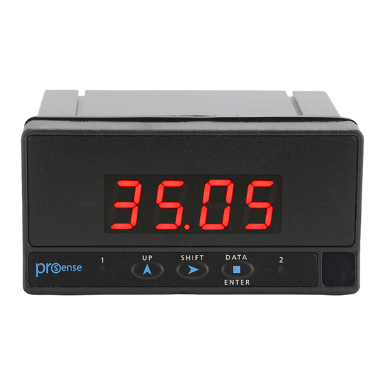
Page 12: Display And Key Pad
User Manual - DPM2 Series Process Panel Meters Display and Key Pad Pro mode is when configuration menu is entered to program the indicator. RUN is the normal mode in which display shows the reading according to configuration and input signal value. -
Page 13: Configuration
User Manual - DPM2 Series Process Panel Meters Configuration When the power is applied to the meter, a display test begins automatically to check the function of LED’s and digits. Once this test is finished the display shows the internal software version and then the unit goes to RUN mode. -
Page 14: Process
User Manual - DPM2 Series Process Panel Meters Process The parameters to be configured in input process submenu are: Input Type: ±10V or ±200V ±20mA Temperature The parameters to be configured in input ... -
Page 15: Potentiometer
User Manual - DPM2 Series Process Panel Meters Potentiometer No additional configuration is needed for this input type (direct validation). Resistance The only parameter to be configured in input resistance submenu is: RESISTANCE RANGE: . . 999.9 to 999.9Ω... -
Page 16: Display Scaling
User Manual - DPM2 Series Process Panel Meters Display Scaling Display scaling is necessary when adapting display reading to a particular engineering unit. Display range can be configured between -9999 and 9999 for the DPM2 or -1999 to 9999 for the DPM2L. Display scaling is a linear process that consists in introducing two input values, referred as Input 1 and Input 2, and their respective display values, referred as Display 1 and Display 2. -
Page 17: Process Input
User Manual - DPM2 Series Process Panel Meters Process Input In “SCAL” method, all values must be manually introduced through the three frontal keys whereas in “tEAC” method, input signal value must be present at the conector at each point that is intended to be configured. ... -
Page 18: Temperature Input
User Manual - DPM2 Series Process Panel Meters Temperature Input When programmed input type is temperature, thermocouple or Pt100 or Pt1000 sensor, the only parameter to configure is the filter and its configuration is done in the FiLt same way as described for process input. Display scaling is not available for this input type, the unit then will assume a fixed calibrated range depending on sensor type and previously configured units resolution Potentiometer Input... -
Page 19: Resistance Input
User Manual - DPM2 Series Process Panel Meters Resistance Input When programmed input type is resistance, the display can be manually scaled by selecting (uSEr) or the display can be scaled to fixed calibrated ranges (CAL) depending on the resistance range previously configured. -
Page 20: Relay Setpoint Configuration
User Manual - DPM2 Series Process Panel Meters Relay Setpoint Configuration The third menu “SEtP” only appears for the DPM2 with relay outputs. RELAY OUTPUT OPTION Programming steps are equal for both relays on each “SEt1” and “SEt2”... - Page 21 User Manual - DPM2 Series Process Panel Meters TIME DELAY OR HYSTERESIS: dLy: Programmable delay from 0 to 99.9s. . . HyS: Hysteresis in counts within display range. Time Delay: Both relay output actions can be controlled by a configurable time delay from 0 up to 99.9 seconds.
-
Page 22: Additional Functions
User Manual - DPM2 Series Process Panel Meters Additional Functions MAX/MIN and RESET Functions This device detects and stores in memory maximum and minimum values reached by the input signal. This values are kept in memory although power supply is disconnected. When repeatedly pressing SHIFT key, MAX/MIN function shows saved maximum and minimum values in display since last RESET function activation. -
Page 23: Return To Factory Configuration
User Manual - DPM2 Series Process Panel Meters Return to Factory Configuration Run mode To access this menu from RUN mode, press ENTER key and while display shows “Pro” press again ENTER for at least 3 Programming mode seconds. ... - Page 24 User Manual - DPM2 Series Process Panel Meters Configuration Lock-Out Continued If “LiSt” option is selected, display will show momentarily “tLoc”. Total configuration lock-out is activated by selecting “YES”, then routine directly jumps to MAX/MIN lock-out configuration before the ...
- Page 25 User Manual - DPM2 Series Process Panel Meters Configuration Lock-Out Continued It is posible to configure SHIFT key lock-out for MAX/MIN function in the same way as previous configurations. When lock-out is enabled (selecting “YES”) it is not possible to visualize maximum or minimum values by pressing SHIFT key, although instrument internally continues detecting and saving new extreme values reached by input signal.
-
Page 26: Technical Specifications
User Manual - DPM2 Series Process Panel Meters Technical Specifications Technical Specifications Range Input Impedance Resolution Accuracy ±20mA <20Ω 2µA ±(0.1% rdg+15µA) Process Input ±10V 2MΩ ±(0.1% rdg+6mV) ±200V 2MΩ 20mV ±(0.1% rdg+0.1V) 24V±3V @ 30mA Sensor Excitation Maximum Range Measurement Resolution Accuracy... - Page 27 User Manual - DPM2 Series Process Panel Meters Technical Specifications Continued Technique Sigma-Delta Resolution ±16 bits Conversion Conversion rate 20 times per second Range -9999 to +9999 (-1999 to +9999 for large display models), selectable decimal point position Type 4 digit, 14mm (0.55”) or 20mm (0.79”), red LEDs Relay 1, Relay 2 Display...
-
Page 28: Instrumentation Configuration Notes
User Manual - DPM2 Series Process Panel Meters Instrumentation Configuration Notes INPUT: TYPE: RANGE: DISPLAY: SCAL TEACH CONFIG. MODE: INPUT 1: DISPLAY 1: INPUT 2: DISPLAY 2: FILTER (0 ÷ 9): SETPOINTS: SET1: MODE: DLY: HYS: SET2: MODE: DLY: HYS: LOCK-OUT: ACCESS CODE: DPM2 Process User Manual, 1st Edition...
Need help?
Do you have a question about the ProSense DPM2 Series and is the answer not in the manual?
Questions and answers