Table of Contents
Advertisement
Advertisement
Table of Contents

Related Manuals for Automation Direct ProSense DPM1 Series


Summary of Contents for Automation Direct ProSense DPM1 Series
- Page 1 anual DPM1 S enSe erieS igital anel eter ProceSS inPut SignalS Models: DPM1-A-2R-H DPM1-A-2R-L DPM1-A-A2R-H DPM1-A-A2R-L Scan or click the QR code for a series of Configuration and Programming videos for the ProSense DMP Series Panel Meters...
-
Page 2: Table Of Contents
User Manual - DPM1 Series Panel Meters In this Chapter... General Information ......................4 Package Contents ......................4 Recycling Instructions ....................4 General Safety Considerations ..................4 Symbols Identification ....................4 Maintenance ........................5 Technical Support......................5 Agency Approvals ......................5 Device Description ......................6 Dimensions and Mounting ....................7 Installation........................7 Wiring Terminals ......................8 Wiring Examples ......................9... - Page 3 User Manual - DPM1 Series Panel Meters Direct access to the relay setpoints value programming ..........22 Analog output ......................22 Analog output menu diagram ..................23 Technical Specifications ....................24 Notes: ..........................25 DPM1 User Manual, 1st Edition...
-
Page 4: General Information
User Manual - DPM1 Series Panel Meters General Information Package Contents • DPM1 Series digital panel meter • Quick start guide • Mounting panel accessories (a sealing gasket and fixing clip) • Wiring accessories (plug-in terminal block connectors and 2 key tools for wire insertion) •... -
Page 5: Maintenance
User Manual - DPM1 Series Panel Meters Maintenance To ensure instrument accuracy, it is recommended to check its performance according to the technical specifications listed in this manual. For front cover cleaning, just wipe with a damp cloth and neutral soap product. DO NOT USE SOLVENTS! Technical Support We strive to make our manuals the best in the industry. -
Page 6: Device Description
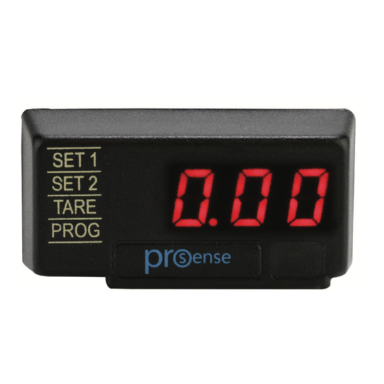
User Manual - DPM1 Series Panel Meters Device Description These models in the ProSense DPM1 series offers a simple, low cost digital display of analog process signals. The 4-digit red LED display is easily scaled into any engineering units from -1999 to 9999 with a selectable decimal point location. -
Page 7: Dimensions And Mounting
User Manual - DPM1 Series Panel Meters Dimensions and Mounting Fixing clip Sealing gasket DPM1 Meter Panel mounting surface Installation To install the instrument, prepare a 45mm x 22mm Installation panel cut-out and slide the unit inwards making sure Dimensions to place the sealing gasket between the front side panel 48 x 24 x 125.1mm (1/32 DIN) 45 x 22mm... -
Page 8: Wiring Terminals
User Manual - DPM1 Series Panel Meters Wiring Terminals Analog output terminals (DPM1-A-A2R-H & DPM1-A-A2R-L only) CN3* Relay 1 Relay 2 1 +60V / +10VDC -0/4-20mA Supply Supply 2 +20mA DC N.O. Contact N.O. Contact 3 +100mV 1 Line 1 -VDC +0/4-20mA 4 -IN / - Excitation 2 Neutral... -
Page 9: Wiring Examples
User Manual - DPM1 Series Panel Meters This instrument conforms with the following community directives: EMC 2004/108/CE and LVD 2006/95/CE. Refer to the instructions in this manual to preserve safety protections. WARNING: If this instrument is not installed and used in accordance with these instructions, the protection provided against hazards may be impaired. -
Page 10: Programming Keys
User Manual - DPM1 Series Panel Meters Programming Keys ENTER Enters configuration and validates data and parameters. SHIFT: Selects mode or shifts blinking digit in configuration. UP: Increases value of blinking digit in configuration mode. (Bottom View) Configuration When the power is applied to the meter, a display test begins automatically to check the function of the LED’s and digits. -
Page 11: Programming Numerical Values
User Manual - DPM1 Series Panel Meters Programming numerical values When the parameter is a numerical value, the display will show the first of the digit to be programmed blinking. Digit selecting: Press repeatedly the SHIFT key to shift from left to right over all the display digits. -
Page 12: Input Configuration
User Manual - DPM1 Series Panel Meters Input Configuration The figure below shows the input configuration menu. Programming Keys (Bottom View) ENTER Enters configuration and validates data and parameters. SHIFT: Selects mode or shifts blinking digit in configuration. UP: Increases value of blinking digit in configuration mode. -
Page 13: Display Configuration
User Manual - DPM1 Series Panel Meters Display Configuration Filter level Brightness selection selection from 0 to 9 from 1 to 4 Enter the input signal value and display value for the first ... -
Page 14: Scaling
User Manual - DPM1 Series Panel Meters Scaling Scaling consists of assigning a display value to each input signal value. In linear processes it is achieved by programming two coordinates (InP1, dSP1) and (InP2, dSP2), between which is established a linear relation where each input signal value corresponds to a display value. -
Page 15: Programming Of A Nonlinear Process
User Manual - DPM1 Series Panel Meters Programming of a nonlinear process Access the first two input-display points by pressing the ENTER key. To access the programming of the rest of the points, press ENTER key for 3s after entering the display value of point 2. From here the progression is achieved by pressing ENTER key. -
Page 16: Additional Functions
User Manual - DPM1 Series Panel Meters Additional Functions Several functions can be controlled via the Key Pad that will produce different actions depending on the instrument operating mode: TARE and Reset TARE functions To configure the meter for Tare mode, press the UP key while in RUN mode and the meter will store the currently displayed value as the tare value (unless it is over scaled) and the TARE Led will light. - Page 17 User Manual - DPM1 Series Panel Meters Run Mode <3s Programming Mode If parameter lock out has been enabled, dAtA will be displayed instread of Pro >3s Enter code 74 Save value Run Mode ...
-
Page 18: Configuration Lock Out
User Manual - DPM1 Series Panel Meters Configuration Lock Out The meter is delivered with the programming not locked out, giving access to all the programming levels. Once completed the meter programming the following security measures are recommended: 1. Lock out the programming access to prevent from programmed parameters modifications. 2. - Page 19 User Manual - DPM1 Series Panel Meters keep this code in a safe place (Do not count on your memory). This personal code makes the default code useless. If an incorrect code is entered, the meter will return automatically to the run mode. Total lockout programming is achieved by changing ALL to Yes.
-
Page 20: Output Options
User Manual - DPM1 Series Panel Meters Output Options All output are optoisolated with respect to input signal and power supply. Relay Configuration Introduction All DPM1 models with -2R option are equipped with 2 relays that can provide individual alarm and control capabilities. Each relay can be configured to function based on independent setpoint values within the full configured display range, time delay (in seconds), hysteresis (in counts of display) and selectable HI/LO acting. - Page 21 User Manual - DPM1 Series Panel Meters Setpoint 1 configuration block Delay / Hysteresis selection Delay: from 0 to 99s Hysteresis: From 0000 to 9999 points of display. Activating mode selection: Lo: Low level activation ...
-
Page 22: Direct Access To The Relay Setpoints Value Programming
User Manual - DPM1 Series Panel Meters Direct access to the relay setpoints value programming It is possible to directly access the relay setpoint values without the need to go through the programming menu just by pressing the UP key in Pro mode, as shown in diagram below. Run Mode ... -
Page 23: Analog Output Menu Diagram
User Manual - DPM1 Series Panel Meters Analog output menu diagram gramación Analog output e la salida . configuration nalógica elección 0-20mA or 0-20mA ó 4-20mA Selection -20mA Display para salida Display for analógica 0/4mA out ... -
Page 24: Technical Specifications
User Manual - DPM1 Series Panel Meters Technical Specifications Technical Specifications Range Resolution Input Impedance Accuracy ±10V 1MΩ ±(0.1% rdg+3mV) ±60V 1MΩ ±(0.1% rdg+18mV) Input ±100mV 10µV 100MΩ ±(0.1% rdg+30µV) ±20mA 1µA 12.1Ω ±(0.1% rdg+6µA) 20V±5VDC @ 30mA Sensor Excitation Temperature coefficient 100ppm/°C Warm-up time... -
Page 25: Notes
User Manual - DPM1 Series Panel Meters Notes: DPM1 User Manual, 1st Edition...
Need help?
Do you have a question about the ProSense DPM1 Series and is the answer not in the manual?
Questions and answers