Table of Contents
Advertisement
Quick Links
P
S
ro
enSe
D
igital
F
requency
r
ate
c
hronoMeter
DPM3-P-H
DPM3-P-A2R-H
Scan or click the QR code for a series of Configuration and Programming
videos for the ProSense DMP Series Panel Meters
u
M
Ser
anual
DPM3-P S
P
anel
/ t
achoMeter
/ c
ounter
Models:
DPM3-P-L
DPM3-P-A2R-L
erieS
M
eter
/
M
oDeS
/
Advertisement
Table of Contents

Subscribe to Our Youtube Channel
Related Manuals for Automation Direct ProSense DPM3-P Series


Summary of Contents for Automation Direct ProSense DPM3-P Series
- Page 1 anual DPM3-P S enSe erieS igital anel eter requency achoMeter ounter hronoMeter oDeS Models: DPM3-P-H DPM3-P-L DPM3-P-A2R-H DPM3-P-A2R-L Scan or click the QR code for a series of Configuration and Programming videos for the ProSense DMP Series Panel Meters...
-
Page 2: Table Of Contents
User Manual - DPM3-P Series Digital Panel Meters In this Chapter... General Information ......................4 Package Contents ......................4 Recycling Instructions ....................4 General Safety Considerations ..................4 Symbols Identification ....................4 Maintenance ........................5 Technical Support ......................5 Agency Certifications ....................5 Device Description ......................6 Dimensions and Mounting ....................7 Installation........................7 Wiring Terminals ......................8 Wiring Examples ......................10... - Page 3 User Manual - DPM3-P Series Digital Panel Meters Chronometer Configuration ..................20 Inputs .........................20 Measure ........................20 Display ........................20 Offset .........................20 Run Mode Programming ....................21 Frequency and Tachometer Modes Configuration ............22 Inputs .........................22 Measure ........................22 Display ........................22 Totalizer ........................22 Direction of Rotation Indication..................22 Frequency and Tachometer Modes Programming Diagram ........23 Frequency and Tachometer Configurations ..............23 Tachometer Duty (PWM) ....................25...
-
Page 4: General Information
User Manual - DPM3-P Series Digital Panel Meters General Information Package Contents • DPM3-P Series digital panel meter • Quick start guide • Mounting panel accessories (a sealing gasket and 2 fixing clips) • Wiring accessories (plug-in terminal block connectors and 2 key tools for wire insertion) •... -
Page 5: Maintenance
User Manual - DPM3-P Series Digital Panel Meters Maintenance To ensure instrument accuracy, it is recommended to check its performance according to the technical specifications listed in this manual. For front cover cleaning, just wipe with a damp cloth and neutral soap product. DO NOT USE SOLVENTS! Technical Support We strive to make our manuals the best in the industry. -
Page 6: Device Description
User Manual - DPM3-P Series Digital Panel Meters Device Description The ProSense DPM3-P series offers a simple, feature packed digital display for counter, chronometer, frequency, tachometer, rate, and pulse width modulated (PWM) applications. The DPM3-P has a 5-digit, 14mm character height, tri-color red, green or amber LED, accepts input from AC voltage, magnetic sensors, NPN/PNP sensors, NAMUR sensors, TTL/24V encoders, or switched contacts, and provides selectable sensor excitation voltages. -
Page 7: Dimensions And Mounting
User Manual - DPM3-P Series Digital Panel Meters Dimensions and Mounting (2) Fixing clips Sealing gasket DPM3 Meter Panel mounting surface Dimensions mm [in] Installation To install the meter, prepare a 92mm x 45mm panel cut-out and slide the unit inwards making sure to place the sealing gasket between the front side panel and the front bezel. -
Page 8: Wiring Terminals
User Manual - DPM3-P Series Digital Panel Meters Wiring Terminals 1 2 3 4 5 6 7 8 1 2 3 4 DPM3-P-A2R-H & DPM3-P-A2R-L AC Supply DC Supply Signal Inputs Line Neutral Not used Relay 2 SPDT Relay 1 SPDT (+) 20V Excitation Polarity insensitive for (+) 8.2 V Excitation for NAMUR... - Page 9 User Manual - DPM3-P Series Digital Panel Meters WARNING: If this instrument is not installed and used in accordance with these instructions, the protection provided against hazards may be impaired. To meet the requirements of EN 61010-1 standard, where the unit is permanently connected to main supply, it is obligatory to install a circuit breaking device easily reach by the operator and clearly marked as the disconnecting device.
-
Page 10: Wiring Examples
User Manual - DPM3-P Series Digital Panel Meters Wiring Examples MAGNETIC SENSOR SWITCHED CONTACT B INPUT A INPUT B INPUT A INPUT NAMUR SENSOR ENCODER EXC COMM OUTB OUTA B INPUT A INPUT ENCODER PNP/ NPN SENSOR (only 1 input) 10- 300 Vac EXC OUT COMM EXC OUT COMM... -
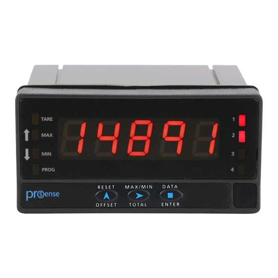
Page 11: Display And Keypad
User Manual - DPM3-P Series Digital Panel Meters Display and Keypad TARE PROG RESET MAX/MIN DATA OFFSET ENTER TOTAL Programming Panel Description Run Mode Programming Mode Indicates that there is an offset TARE value programmed Solid indicates rotation sense or count polarity;... -
Page 12: Configuration
User Manual - DPM3-P Series Digital Panel Meters Configuration When power is applied to the meter, a display test begins automatically to check the function of the LED’s and digits. Once this test is finished the display shows the internal software version and then the unit goes to RUN mode. -
Page 13: Input Configuration
User Manual - DPM3-P Series Digital Panel Meters will be able to take a value in the range -99999 to 99999, without taking into account the decimal point. In these case the first digit shows 0, 1, -1, 2, 3 or -. Completion of each submenu routine returns the meter to Pro mode. -
Page 14: Counter Mode Programming Diagram
User Manual - DPM3-P Series Digital Panel Meters Counter Mode Programming Diagram ModE Count CHron FrEC tACH updo IndEP dIrEC PHASE InAB Programming Keys -Pro- ENTER: Vertical displacement. UP: Changes active digit. SHIFT: Horizontal displacement. Counter Configuration Inputs The counter has two inputs, the A input receives the pulses to count, and the B input serves to inhibit the count or to change the count direction, except in case of bidirectional counter IndEP where the second input is also used to count pulses. -
Page 15: Variables
User Manual - DPM3-P Series Digital Panel Meters Variables The main variable of the counter is the PROCESS variable that is the number of pulses registered from the last RESET operation. If the totalizer option is enabled, there are PROC and TOTAL variables. The TOTAL variable counts the total number of pulses received, independently of the reset operations that may take place in the process display. -
Page 16: Counter Mode Programming
User Manual - DPM3-P Series Digital Panel Meters Counter Mode Programming The input setup is available on the ‘CnInp’ module which allows configuration of the counter mode and totalizer operation. Counter Modes uP: Up count do: Down count In-A: Allows count on A input regardless of input B InA-B: Pulses applied at the A input are added or subtracted to the count display if the B input is at low level and being used as inhibited input uP-do IndEP: Pulses applied at the A input are added to the count display while pulses at the... -
Page 17: Counter Mode Display Programming Diagram
User Manual - DPM3-P Series Digital Panel Meters Counter Mode Display Programming Diagram CndSP dISPL totAL ProC brIGH dECP - Hi - - Lo - 88888 ModE CoLor green amber oFFS -Pro- ±00000 dECP ProG ProG ProG FACt 88888. totAL totAL totAL F.diU... -
Page 18: Totalizer Option
User Manual - DPM3-P Series Digital Panel Meters Totalizer Option The totalizer is optional and has a decimal point and multiplying factor independent of the partial counter. The totalizer indication range is from 99999999 to -99999999. The decimal point has a maximum of five positions, from digit 0 to 4. The multiplying factor is programmed in the same way as that of the partial counter (0.0001 to 99999). -
Page 19: Other Display Options
User Manual - DPM3-P Series Digital Panel Meters Other Display Options In the sub-menu (dISPL) the following display modes can be selected: Brightness: Hi (normal luminosity) / Lo (low luminosity) Color: It is possible to assign a different color to: (run) process display (totAL) display totalizer (ProG) display programming... -
Page 20: Chronometer Configuration
User Manual - DPM3-P Series Digital Panel Meters Chronometer Configuration Inputs The meter has two inputs for the START and STOP signals that provide different types of time measurement. There are two selectable operating modes: mode In-A, that allows to measure the width of a pulse, mode In-AB, that is used to measure the difference between two signals Measure Time measurement is initiated on a rising edge of the START input. -
Page 21: Run Mode Programming
User Manual - DPM3-P Series Digital Panel Meters Run Mode Programming Start and Stop modes Mode In-A MODE In-A START on rising edge of input A. STOP on falling edge of input A. display input A MODE In-AB START on rising edge if input A. STOP on rising edge of input B. -
Page 22: Frequency And Tachometer Modes Configuration
User Manual - DPM3-P Series Digital Panel Meters Frequency and Tachometer Modes Configuration Inputs In frequency and tachometer modes both inputs of the meter are used. The signal providing frequency/rate and count information must be issued to the A input. A second signal may be applied to the B input to control direction of rotation or polarity of the signal. -
Page 23: Frequency And Tachometer Modes Programming Diagram
User Manual - DPM3-P Series Digital Panel Meters Frequency and Tachometer Modes Programming Diagram ModE Count CHron FrEC tACH dutY rAtE dECP 888.88 InP1 InP2 00001 000.1 100.0 -Pro- InP1 InP2 dSP1 dSP2 0000.1 0000.1 0000.1 dECP 0000.1 100.0 0000.1 8888.8 0000.1 Programming Keys... - Page 24 User Manual - DPM3-P Series Digital Panel Meters Decimal Point The decimal point to be programmed in this step is the one that will be displayed which, combined with the Multiplication / Division factor, will allow the indication in units other than rpm, if necessary. Tachometer Rate In the RATE configuration, the tachometer can be scaled to read speed, flow or time directly in the desired units, by entering two parameters: Input Frequency and Desired...
-
Page 25: Tachometer Duty (Pwm)
User Manual - DPM3-P Series Digital Panel Meters Baking Time (min) It is required to monitor the baking time knowing that, at the specified frequency of 30Hz, the time taken for each loaf to bake is 15min 30s. When rate (and frequency) grows, the baking time is reduced proportionally. The rate meter must then be programmed for reverse mode. -
Page 26: Frequency And Tachometer Modes Display Programming Diagram
User Manual - DPM3-P Series Digital Panel Meters Frequency and Tachometer Modes Display Programming Diagram CndSP There is no totalizer in FREC and DUTY mode Programming Keys ENTER: Vertical displacement. dISPL totAL ProC UP: Changes active digit. SHIFT: Horizontal displacement. brIGH FACt - Hi -... - Page 27 User Manual - DPM3-P Series Digital Panel Meters Average Time (tAVG) The meter can display all the readings at a rate of 10 per second (the display refreshes every 100ms) or an average of the readings made during a programmable time: the AVERAGE TIME.
-
Page 28: Total, Max And Min Visualization
User Manual - DPM3-P Series Digital Panel Meters Clear to zero the variable present on display is carried out when releasing the RESET key; being then reinitiated the count, in counter mode or chronometer, from zero or offset. The RESET key will not operate if in the program lock-out routine its corresponding step is activated. -
Page 29: Logic Functions Menu
User Manual - DPM3-P Series Digital Panel Meters Logic Functions Menu Programming Keys ENTER: Vertical displacement. UP: Changes active digit. SHIFT: Horizontal displacement. - - - -- -- -- If the selected function is number 03, the value of the variable to reset must be selected. Another digital input can be assigned to the same function but that acts on another variable, as has been done in the Factory programming: InP1 = Reset PROCESS, InP2 = reset TOTALIZER... -
Page 30: Table Of Programmable Functions
User Manual - DPM3-P Series Digital Panel Meters Table of programmable functions • No.: Number to select the function. • Function: Function name. • Description: Description and characteristics of the function. • Activation by: Falling edge: the function is activated applying a falling edge to the corresponding pin with respect to common. -
Page 31: Configuration Lock Out
User Manual - DPM3-P Series Digital Panel Meters Configuration Lock Out The meter is delivered with the programming not locked out, giving access to all the programming levels. Once completed the meter programming the following security measures are recommended: 1. Lock out the programming access to prevent from programmed parameters modifications. 2. -
Page 32: Lock-Out Menu Diagram
User Manual - DPM3-P Series Digital Panel Meters Lock-out menu diagram The following figure shows the lock-out menu. The access to this menu is accomplished from the run mode by pressing the ENTER key for 3 seconds, until the “CodE” indication appears. The meter is shipped from factory with the following default code: “0000”. -
Page 33: Output Options
User Manual - DPM3-P Series Digital Panel Meters Output Options All outputs are optoisolated with respect to input signal and power supply. 2500Vrms for 1 minute to signal terminals (CN2) and relays terminals (CN3 or CN4). 2500Vrms for 1 minute to power terminals (CN1) and relays terminals (CN3 or CN4). Relay Configuration Introduction Some DPM3 models are equipped with 2 relays that can provide individual alarm and control... -
Page 34: Relay Programming In Frequency Or Tachometer Modes Diagram
User Manual - DPM3-P Series Digital Panel Meters The time delay is the time that takes the output to activate after passing through the setpoint in the up or down direction, while the hysteresis band will be selected asymmetrical i.e. only acts on the output deactivation edge. -
Page 35: Relay Programming In Counter Or Chronometer Modes Diagram
User Manual - DPM3-P Series Digital Panel Meters Relay Programming in Counter or Chronometer Modes Diagram The complete programming of only one of the Setpoints is shown, it is the same for Set2. SEtP The "track" mode is only SEt 1 SEt 2 available for Set2 -off-... -
Page 36: Description Of Relay Operation In Counter Or Chronometer Modes Or With Active Totalizer In Frequency Or Tachometer Modes
User Manual - DPM3-P Series Digital Panel Meters Description of Relay Operation in Counter or Chronometer Modes or with Active Totalizer in Frequency or Tachometer Modes Mode 1 - IndEP: When the process or total counter arrives, (depending on the programming) at the set point value, the output is activated according to whether it is a pulse or a latch , whether it is lower or higher than the programmed value. - Page 37 User Manual - DPM3-P Series Digital Panel Meters Mode 3 - Stop: The process counter or total (the one referred to the set point) if it is active is stopped when it reaches the setpoint. Counters are restarted when the counter to which the setpoint is referred is reset.
-
Page 38: Direct Access To The Relay Setpoints Value Programming
User Manual - DPM3-P Series Digital Panel Meters Direct access to the relay setpoints value programming It is possible to directly access the relay setpoint values without the need to go through the programming menu just by pressing the UP key in Pro mode, as shown in diagram below. Setpoints configured at “off ”... -
Page 39: Analog Output
User Manual - DPM3-P Series Digital Panel Meters Analog output Introduction Some DPM3 models include an analog output (4-20 mA). The output is optoisolated with respect to the signal input and the power supply. The meter provides a two terminal connector [(+ ) and (-)] that drives out a signal variation from 4mA to 20mA proportional to a user-defined display range. -
Page 40: Return To Factory Configuration
User Manual - DPM3-P Series Digital Panel Meters Return to Factory Configuration After accessing programming mode, Pro press and hold the up key for 3 seconds. Allows entering a code of access to the reset of the configuration parameters, this code is 74. When entering this code the meter shows the LoAdIng dEFAuLt ConFIGurAtIon legend, and then StorE, which means that they have been stored in the non volatile memory of the meter. -
Page 41: Technical Specifications
User Manual - DPM3-P Series Digital Panel Meters Technical Specifications Technical Specifications 20kHz (without totalizer) Maximum Frequency 8kHz (with totalizer) Tachometer/Frequency 1kHz (duty) Mode Minimum Frequency 0.01 Hz Without totalizer 11kHz Counter Mode With totalizer 9kHz AC Voltage Input Range 10 to 300 VAC Vin (AC) >... - Page 42 User Manual - DPM3-P Series Digital Panel Meters Technical Specifications Continued Type 5 LED digits 14mm (0.55”) (Programmable color Red, Green, Amber) LEDs 8, functions and outputs status Decimal Point Programmable Positive overflow indication OvEr Negative overflow indication -OvEr Counter display limits Process -99999 to 99999 Display Totalizer...
Need help?
Do you have a question about the ProSense DPM3-P Series and is the answer not in the manual?
Questions and answers