Table of Contents
Advertisement
u
P
S
ro
enSe
D
igital
for ProceSS
anD loaD cell inPut SignalS
DPM3-AT-H
DPM3-AT-2R-H
DPM3-AT-4R-H
DPM3-AT-A-H
DPM3-AT-A2R-H
Scan or click the QR code for a series of Configuration and Programming
videos for the ProSense DMP Series Panel Meters
M
Ser
anual
DPM3 S
P
anel
,
teMPerature
Models:
DPM3-AT-L
DPM3-AT-2R-L
DPM3-AT-4R-L
DPM3-AT-A-L
DPM3-AT-A2R-L
erieS
M
eter
Advertisement
Table of Contents

Related Manuals for Automation Direct ProSense DPM3 Series


Summary of Contents for Automation Direct ProSense DPM3 Series
- Page 1 anual DPM3 S enSe erieS igital anel eter for ProceSS teMPerature anD loaD cell inPut SignalS Models: DPM3-AT-H DPM3-AT-L DPM3-AT-2R-H DPM3-AT-2R-L DPM3-AT-4R-H DPM3-AT-4R-L DPM3-AT-A-H DPM3-AT-A-L DPM3-AT-A2R-H DPM3-AT-A2R-L Scan or click the QR code for a series of Configuration and Programming videos for the ProSense DMP Series Panel Meters...
-
Page 2: Table Of Contents
User Manual - DPM3 Series Panel Meters In this Chapter... General Information ......................4 Package Contents ......................4 Recycling Instructions ....................4 General Safety Considerations ..................4 Symbols Identification ....................4 Maintenance ........................5 Technical Support ......................5 Agency Approvals ......................5 Device Description ......................6 Dimensions and Mounting ....................7 Installation........................7 Wiring Terminals ......................8 Wiring Examples ......................9... - Page 3 User Manual - DPM3 Series Panel Meters Weighted Average Filter P ..................19 Round ........................19 Brightness ........................20 Eco ..........................20 Input Error ........................20 Additional Functions ....................20 MAX/MIN function.....................22 Logic functions ......................23 Logic functions menu ....................24 Table of programmable functions ................24 Configuration Lock Out ....................25 Lock-out menu diagram .....................26 Output Options ......................28 Relay Configuration ....................28...
-
Page 4: General Information
User Manual - DPM3 Series Panel Meters General Information Package Contents • DPM3 Series digital panel meter • Quick start guide • Mounting panel accessories (a sealing gasket and 2 fixing clips) • Wiring accessories (plug-in terminal block connectors and 2 key tools for wire insertion) •... -
Page 5: Maintenance
User Manual - DPM3 Series Panel Meters Maintenance To ensure instrument accuracy, it is recommended to check its performance according to the technical specifications listed in this manual. For front cover cleaning, just wipe with a damp cloth and neutral soap product. DO NOT USE SOLVENTS! Technical Support We strive to make our manuals the best in the industry. -
Page 6: Device Description
User Manual - DPM3 Series Panel Meters Device Description The ProSense DPM3 series offers a simple, feature packed digital display of analog process signals, temperature in either Fahrenheit or Celsius from RTD or Thermocouple temperature sensors, load cell, or potentiometer inputs. The 5-digit tri-color red, green or amber LED display is easily scaled into any engineering units from -19999 to 39999 with a selectable decimal point location. -
Page 7: Dimensions And Mounting
User Manual - DPM3 Series Panel Meters Tare Hold • Filtering to minimize display bounce • Display brightness adjustment • 3 year warranty Dimensions and Mounting (2) Fixing clips Sealing gasket DPM3 Meter Panel mounting surface Installation To install the instrument, prepare a 92mm x 45mm Installation panel cut-out and slide the unit inwards making sure to place the sealing gasket between the front side panel... -
Page 8: Wiring Terminals
User Manual - DPM3 Series Panel Meters Wiring Terminals 2 1 2 3 4 5 6 7 8 1 2 3 4 2 SPDT Relays (-2R) CN4 (Relay 2) CN5 (Relay 1) Input Signal / Excitation Supply Supply Process Temperature Load Cell 1 Line 1 VDC -EXC24V... -
Page 9: Wiring Examples
User Manual - DPM3 Series Panel Meters This instrument conforms with the following community directives: EMC 2004/108/CE and LVD 2006/95/CE. Refer to the instructions in this manual to preserve safety protections. WARNING: If this instrument is not installed and used in accordance with these instructions, the protection provided against hazards may be impaired. -
Page 10: Process Input Signal Wiring Diagram (V)
User Manual - DPM3 Series Panel Meters Process Input Signal Wiring Diagram (V) 4 wire Connection POTENTIOMETER CIÓMETRO +EXC (10V) EXTERNAL TRANSDUCER EXCITATION +OUT -OUT 0- 10 V 3 wire Connection 2 wire Connection EXTERNAL TRANSDUCER EXCITATION 0- 10 V 0- 10 V 4 wire Connection TRANSDUCER... -
Page 11: Thermocouple (J, K, T, N) Sensor Input Wiring Diagram
User Manual - DPM3 Series Panel Meters Thermocouple (J, K, T, N) Sensor Input Wiring Diagram Terminals Thermocouple type J, K, T, N DPM3 User Manual, 1st Edition... -
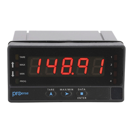
Page 12: Display And Key Pad
User Manual - DPM3 Series Panel Meters Display and Key Pad TARE PROG MAX/MIN DATA MICRA ENTER Programming Panel Description Run Mode Programming Mode TARE Indicates tare in the memory Indicates peak displayed Indicates valley displayed PROG Indicates programming mode DISPLAY Displays the input variable Displays programming parameters... -
Page 13: Programming Numerical Values
User Manual - DPM3 Series Panel Meters present (Anout), logic functions configuration (LoGIn). Press ENTER to access the submenus under each main menu. If configuration has been totally locked-out, when pressing ENTER to access the main menu level, the display shows dAtA instead of Pro. This indicates that it is only possible to see programmed information and that it is not allowed to modify any parameter from the entire configuration. -
Page 14: Input Configuration
User Manual - DPM3 Series Panel Meters Input Configuration The figure below shows the input configuration menu. Divided into four submenus, each one of them separated by the dotted line in the manual, each menu corresponds to the programming of the different types of input: process, load cell, Pt100 RTD and thermocouple. Programming Keys (Bottom view) ENTER: Vertical displacement. -
Page 15: Process Input
User Manual - DPM3 Series Panel Meters Process input The DPM3 is designed to measure all kinds of process variable with direct indication in engineering units. The parameter to configure as process indicator is the input type, in volts in a -10 V to 10 V range and in milliamperes in a -20 mA to 20 mA range. -
Page 16: Thermocouple Input
User Manual - DPM3 Series Panel Meters A) Reading units in degree Celsius “ºC” or Fahrenheit “ºF”. B) Resolution in tenth of degrees “0.1º” or in whole degrees “1º”. C) Offset. The instrument comes from factory with offset=0 After entering these parameters, the display range and linearization are adjusted automatically. Thermocouple Input When configuring the meter for thermocouple input, the temperature ranges and resolution available are:... -
Page 17: Display Configuration
User Manual - DPM3 Series Panel Meters Display Configuration Programming Key Pad ENTER: Vertical displacement. UP: Changes active digit. SHIFT: Horizontal displacement. ±.... -
Page 18: Programming Of The Scale
User Manual - DPM3 Series Panel Meters Display Input In order to obtain more accuracy it is recommended to program the highest possible number of points and reduce the segment length. Input values must always be programmed in an increasing or decreasing order. Avoid assigning two different display values to two equal input values. -
Page 19: Scal Method
User Manual - DPM3 Series Panel Meters SCAL method The input and display values are programmed manually. This method can be used when the value of the signal supplied by the transducer at each points of the process is known. tEACH method The input values are introduced directly from actual process values. -
Page 20: Brightness
User Manual - DPM3 Series Panel Meters Brightness Display brightness level selection. Hi: high brightness Lo: low brightness Display color selection between green, red or amber is possible for both RUN and Pro modes. Allows choosing an operative mode with an up to 45% of ENERGY SAVING* on: After a programmable time without pressing any key, display will turn off leaving only the right decimal point flashing;... - Page 21 User Manual - DPM3 Series Panel Meters pressing the UP key again will add the currently displayed value to the previously stored tare value resulting in a new stored tare value. To reset the tare value to zero, press the UP key for 3 seconds.
-
Page 22: Max/Min Function
User Manual - DPM3 Series Panel Meters MAX/MIN function With the meter in RUN mode: Activated after pressing the SHIFT key. From RUN mode, a press shows the maximum value read by the instrument since the last time it has been switched on, unless a RESET MAX/MIN is done, the MAX led will light up. -
Page 23: Logic Functions
User Manual - DPM3 Series Panel Meters Direct Access to Relay Setpoints If the DPM3 has relay outputs present the meter allows direct access to the programming of the setpoint values. After accessing programming mode, Pro, pressing the UP key provides access to each relay setpoint value. -
Page 24: Logic Functions Menu
User Manual - DPM3 Series Panel Meters Logic functions menu Programming Key Pad ENTER: Vertical displacement. UP: Changes active digit. SHIFT: Horizontal displacement. - - - -- -- -- Table of programmable functions • Nº: Number to select the function. •... -
Page 25: Configuration Lock Out
User Manual - DPM3 Series Panel Meters Configuration Lock Out The meter is delivered with the programming not locked out, giving access to all the programming levels. Once completed the meter programming the following security measures are recommended: 1. Lock out the programming access to prevent from programmed parameters modifications. 2. -
Page 26: Lock-Out Menu Diagram
User Manual - DPM3 Series Panel Meters Lock-out menu diagram The following figure shows the lock-out menu. The access to this menu is accomplished from the run mode by pressing the ENTER key for 3 seconds, until the “CodE” indication appears. The instrument is shipped from factory with the following default code: “0000”. - Page 27 User Manual - DPM3 Series Panel Meters 0 allows its programming 1 locks the access to programming * Only appear if the corresponding Previous options are present in the meter Page Enter Change 0 / 1? ...
-
Page 28: Output Options
User Manual - DPM3 Series Panel Meters Output Options All options are optoisolated with respect to input signal and power supply. Relay Configuration Introduction Some DPM3 models are equipped with either 2 or 4 relays that can provide individual alarm and control capabilities. -
Page 29: Relay Configuration Menu Diagram
User Manual - DPM3 Series Panel Meters Delay action Asymmetrical hysteresis Relay Configuration menu diagram The complete programming of one of the setpoints is showed here, it is valid for the rest of the setpoints. ... -
Page 30: Direct Access To The Relay Setpoints Value Programming
User Manual - DPM3 Series Panel Meters Direct access to the relay setpoints value programming It is possible to directly access the relay setpoint values without the need to go through the programming menu just by pressing the UP key in Pro mode, as shown in diagram below. Setpoints configured at “off”... -
Page 31: Analog Output Menu Diagram
User Manual - DPM3 Series Panel Meters In case of ‘display overflow’, ‘sensorbreak’ or ‘input error’, the output signal can be configured to be fixed at a high level ‘Hi’ or a low level ‘Lo’. Analog output menu diagram Programming Key Pad ENTER: Vertical displacement. -
Page 32: Technical Specifications
User Manual - DPM3 Series Panel Meters Technical Specifications Technical Specifications Range Input Impedance Accuracy Resolution Process ±10VDC 1MΩ ±(0.1% rdg + 1 digit) ±20mA DC 15Ω ±(0.1% rdg + 1 digit) 1µA Sensor 24V@60mA, 10V @ 60mA Excitation Range Input Impedance Accuracy Resolution... - Page 33 User Manual - DPM3 Series Panel Meters Technical Specifications Technique Sigma-Delta Conversion Resolution ±15 bits Conversion rate 20 times per second Temperature 100 ppm/°C coefficient Accuracy Warm-up time 10 minutes Conditions Temperature 23°C±5°C Range -19999 / +39999, 5 LED digits 14mm (Programmable color Red, Green, Amber) LEDs 8, functions and outputs status Process / Load cell...
-
Page 34: Notes
User Manual - DPM3 Series Panel Meters Notes: DPM3 User Manual, 1st Edition...
Need help?
Do you have a question about the ProSense DPM3 Series and is the answer not in the manual?
Questions and answers