
Subscribe to Our Youtube Channel
Related Manuals for Automation Direct ProSense LPM1 Series


Summary of Contents for Automation Direct ProSense LPM1 Series
- Page 1 ProSense LPM1 Series Meter Loop-powered 4 to 20mA process diplay unit Operating Instructions...
-
Page 2: Table Of Contents
Operating Instructions - ProSense LPM1 Series Meter 1 Document Information ���������������������������������������������������������������3 1.1 Document function ..................3 1.2 Document conventions ..................3 2 Basic Safety Instructions �������������������������������������������������������������5 2.1 Requirements for personnel ................5 2.2 Designated use ....................6 2.3 Workplace safety ....................6 2.4 Operational safety ..................6 2.5 Product safety ....................7... -
Page 3: Document Information
Operating Instructions - ProSense LPM1 Series Meter 1 Document Information 1.1 Document function These Operating Instructions contain all the information that is required in various phases of the life cycle of the device: from incoming acceptance and storage, to mounting, connection, operation and commissioning through to troubleshooting, maintenance and disposal. - Page 4 Operating Instructions - ProSense LPM1 Series Meter 1.2.2 Electrical symbols Symbol Meaning Equipotential connection A connection that has to be connected to the plant grounding system: This may be a potential equalization line or a star grounding system depending on national or company codes of practice.
-
Page 5: Basic Safety Instructions
Operating Instructions - ProSense LPM1 Series Meter 1.2.4 Symbols for graphics Symbol Meaning 1, 2, 3, ... Item numbers Series of steps … A, B, C, ... Views A-A, B-B, C-C, ... Sections Flow direction Hazardous area Indicates a hazardous area. -
Page 6: Designated Use
Operating Instructions - ProSense LPM1 Series Meter • Following instructions and basic conditions The operating personnel must fulfill the following requirements: • Being instructed and authorized according to the requirements of the task by the facility’s owner/operator • Following the instructions in these Operating Instructions 2.2 Designated use... -
Page 7: Product Safety
Operating Instructions - ProSense LPM1 Series Meter 2.5 Product safety This measuring device is designed in accordance with good engineering practice to meet state-of-the-art safety requirements, has been tested, and left the factory in a condition in which it is safe to operate. -
Page 8: Installation Conditions
Operating Instructions - ProSense LPM1 Series Meter • Pack the device so that it is protected against impact for storage and transport. The original packaging provides optimum protection. • The permitted storage temperature is –40 to +85 °C (–40 to +185 °F);... - Page 9 Operating Instructions - ProSense LPM1 Series Meter 2. Fit the mounting clips on the side of the housing and tighten the set screws. Tightening screw torque: 0.4 to 0.6 Nm 4.3.2 Field housing (LPM1-A-ENC and LPM1-A-HAZ) Pipe mounting (with optional LPM1-BKT mounting kit) The device can be mounted on a pipe with a diameter of up to 50.8 mm (2 in)
- Page 10 Operating Instructions - ProSense LPM1 Series Meter Wall mounting (with optional LPM1-BKT mounting kit) 1. Use the mounting plate as a stencil and make two 6mm (0.24 in) bore holes, 82mm (3.23 in) apart. Secure the plate on the wall with 2 screws (not supplied).
-
Page 11: Post-Installation Check
Operating Instructions - ProSense LPM1 Series Meter 4.4 Post-installation check 4.4.1 Display unit in the panel-mount housing • Is the seal undamaged? • Are the mounting clips securely fastened on the housing of the device? • Are the set screws properly tightened? •... -
Page 12: Quick Wiring Guide
Operating Instructions - ProSense LPM1 Series Meter Operation of the spring terminals 1. When using rigid cables with a ferrule, just plug the cable into the terminal. No tools required. With flexible wires the spring mechanism of the terminal must be operated as shown in step 2. - Page 13 Operating Instructions - ProSense LPM1 Series Meter Connection without backlighting Connection with backlighting Connection with transmitter power supply and transmitter (sinking) LPM1 LPM1 Meter Meter 1 Transmitter power supply 1 Transmitter power supply 2 4 to 20mA transmitter 2 4 to 20mA transmitter...
-
Page 14: Inserting The Cable, Field Housing
Operating Instructions - ProSense LPM1 Series Meter 5.2 Inserting the cable, field housing TX20 M16 Cable Glands LPM1-A-ENC sold separately LPM1-A-HAZ included with meter Inserting the cable, field housing, connection without transmitter power supply (example) 1. Release the housing screws 2. -
Page 15: Connecting To Functional Grounding
Operating Instructions - ProSense LPM1 Series Meter 5.3 Connecting to functional grounding 5.3.1 Panel-mounted device (LPM1-A-PNL) For EMC reasons, the functional grounding should always be connected. Functional grounding terminal (1) on panel-mounted LPM1-A-PNL 5.3.2 Field device (LPM1-A-ENC and LPM1-A-HAZ) For EMC reasons, the functional grounding should always be connected. -
Page 16: Degree Of Protection
Operating Instructions - ProSense LPM1 Series Meter TX20 Ground terminal on field housing 5.4 Degree of protection 5.4.1 Field housing (LPM1-A-ENC and LPM1-A-HAZ) The devices meet all the requirements of IP67. It is absolutely essential to comply with the following points to ensure this protection is guaranteed after mounting or servicing the device: •... -
Page 17: Post-Connection Check
Operating Instructions - ProSense LPM1 Series Meter 5.5 Post-connection check Device condition and specifications Notes Are cables or the device damaged? Visual inspection Electrical connection Notes Does the supply current match the specifications on the nameplate? Are the cables, incl. functional grounding, connected correctly and strain-relieved? -
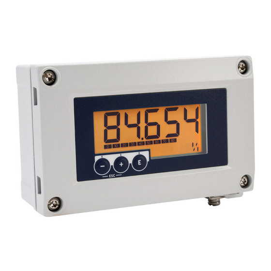
Page 18: Operating Functions
Operating Instructions - ProSense LPM1 Series Meter Enter key; calling up the operating menu, con rming the option/setting parameters in the operating menu Selecting and setting/changing values in the operating menu; pressing the '-' and '+' keys simultaneously takes the user back up a menu level. The con gured value is not saved. -
Page 19: Commissioning
Operating Instructions - ProSense LPM1 Series Meter 7 Commissioning 7.1 Post-installation check and switching on the device Perform the final checks before commissioning the device: • Checklist for “post-installation check” • Checklist for “post-connection check” The device starts after being connected to the 4 to 20 mA circuit. The firmware version appears on the display during the start-up phase. - Page 20 Operating Instructions - ProSense LPM1 Series Meter Diagnostics menu (DIAG) Parameters Values Description AERR Read only The current diagnostic message appears on the display. If two or more messages occur simultaneously, the message with the highest priority is shown on the display.
- Page 21 Operating Instructions - ProSense LPM1 Series Meter Expert menu (EXPRT); a code must be entered In addition to all the parameters in the Setup menu, the Expert menu also contains the parameters described in this table. If you call up the Expert menu, you will be asked to enter the user code (UCODE, default: 0000).
-
Page 22: Troubleshooting
Operating Instructions - ProSense LPM1 Series Meter 8 Troubleshooting 8.1 Error limits as per NAMUR NE 43 The device can be configured for error limits as per NAMUR NE 43. The device displays an error message if a value is outside these limits. -
Page 23: Maintenance
Operating Instructions - ProSense LPM1 Series Meter Diagnostic Short text Corrective Diagnostic behavior Priority number measure S902 Input signal too Check Warning large transmitter for incorrect con guration Diagnostics for the electronics F261 Electronics Replace Alarm module display F283 Memory content •... -
Page 24: Technical Data
Operating Instructions - ProSense LPM1 Series Meter 12 Technical data 12.1 Input Voltage drop Without Backlight ≤ 1.0 V Backlight Enabled Additional 2.9 V 12.1.1 Measured variable The 4 to 20 mA current signal input variable. 12.1.2 Measuring range 4 to 20 mA (scalable, reverse polarity protection) Max. input current 200 mA 12.2 Power supply... -
Page 25: Installation
Operating Instructions - ProSense LPM1 Series Meter 12.3.3 Resolution Signal resolution > 13 bit 12.3.4 Influence of ambient temperature < 0.02 %/K (0.01 %/°F) of measuring range 12.3.5 Warm-up period 10 minutes 12.4 Installation 12.4.1 Mounting location Panel housing (LPM1-A-PNL) The device is designed for use in a panel. - Page 26 Operating Instructions - ProSense LPM1 Series Meter 12.5.2 Storage temperature –40 to 85 °C (–40 to 185 °F) 12.5.3 Climate class IEC 60654-1, Class B2 12.5.4 Altitude Up to 5,000 m (16,400 ft) above MSL in accordance with IEC61010-1 12.5.5 Degree of protection...
-
Page 27: Mechanical Construction
Operating Instructions - ProSense LPM1 Series Meter AEx ia IIC T6 Ga Class I, Division 1, Groups A, B, C & D Intrinsically Safe and Non-Incendive Systems - For Hazardous Locations Class I, Division 2, Groups A, B, C and D •... - Page 28 Operating Instructions - ProSense LPM1 Series Meter Field housing (LPM1-A-ENC, LPM1-A-HAZ) 131 (5.16) 55.5 (2.19) mm (in) LPM1-A-ENC: M16 cable glands sold separately LPM1-A-HAZ: M16 cable glands included (M16 x 1.5, cable diameter 5 to 10 mm (0.2 to 0.39 in)) 12.6.2 Weight...
- Page 29 Operating Instructions - ProSense LPM1 Series Meter 71487579 AutomationDirect 3505 Hutchinson Road Cumming, GA 30040 71487579 1-800-633-0405 www.automationdirect.com LPM1 Series Meter Rev. 1 71487579...
Need help?
Do you have a question about the ProSense LPM1 Series and is the answer not in the manual?
Questions and answers