Table of Contents
Advertisement
Quick Links
Advertisement
Table of Contents

Related Manuals for Automation Direct ProSense DPM1-P Series


Summary of Contents for Automation Direct ProSense DPM1-P Series
- Page 1 anual DPM1-P S enSe erieS igital anel eter requency achoMeter oDeS Models: DPM1-P-A2R-H DPM1-P-A2R-L Scan or click the QR code for a series of Configuration and Programming videos for the ProSense DMP Series Panel Meters...
-
Page 2: Table Of Contents
User Manual - DPM1-P Series Panel Meters In this Chapter... General Information ......................3 Package Contents ......................3 Recycling Instructions ....................3 General Safety Considerations ..................3 Symbols Identification ....................3 Maintenance ........................4 Technical Support ......................4 Agency Certifications ....................4 Device Description ......................5 Dimensions and Mounting ....................6 Installation........................6 Wiring Terminals ......................7 Input Wiring Diagrams ....................8... -
Page 3: General Information
User Manual - DPM1-P Series Panel Meters General Information Package Contents • DPM1-P Series digital panel meter • Quick start guide • Mounting panel accessories (a sealing gasket and fixing clip) • Wiring accessories (plug-in terminal block connectors and 2 key tools for wire insertion) •... -
Page 4: Maintenance
User Manual - DPM1-P Series Panel Meters Maintenance To ensure instrument accuracy, it is recommended to check its performance according to the technical specifications listed in this manual. For front cover cleaning, just wipe with a damp cloth and neutral soap product. DO NOT USE SOLVENTS! Technical Support We strive to make our manuals the best in the industry. -
Page 5: Device Description
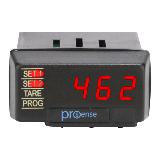
User Manual - DPM1-P Series Panel Meters Device Description These models in the ProSense DPM1-P series offer a simple, low cost digital display for frequency, tachometer, and rate applications. The DPM1-P has a 4-digit 10mm character height red LED display, accepts input from AC voltage, magnetic sensors, NPN/PNP sensors, NAMUR sensors, TTL/24V encoders, or switched contacts, and provides selectable sensor excitation voltages. -
Page 6: Dimensions And Mounting
User Manual - DPM1-P Series Panel Meters Dimensions and Mounting Fixing clip Sealing gasket DPM1 Meter Panel mounting surface Dimensions mm [in] Installation To install the meter, prepare a 45mm x 22mm panel cut-out and slide the unit inwards making sure to place the sealing gasket between the front side panel and the front bezel. -
Page 7: Wiring Terminals
User Manual - DPM1-P Series Panel Meters Wiring Terminals Analog Signal Input Relay 1 Relay 2 Output Supply Supply 1 10 - 600 VAC -0/4-20mA 2 Not used N.O. Contact N.O. Contact 1 Line 1 -VDC +0/4-20mA 3 + Input pulses 2 Neutral 2 +VDC 4 Common... -
Page 8: Input Wiring Diagrams
User Manual - DPM1-P Series Panel Meters Refer to the instructions in this manual to preserve safety protections. WARNING: If this instrument is not installed and used in accordance with these instructions, the protection provided against hazards may be impaired. To meet the requirements of EN 61010-1 standard, where the unit is permanently connected to main supply, it is obligatory to install a circuit breaking device easily reachable by the operator and clearly marked as the disconnecting device. -
Page 9: Programming Keys
User Manual - DPM1-P Series Panel Meters Programming Keys ENTER Enters configuration and validates data and parameters. SHIFT: Selects mode or shifts blinking digit in configuration. UP: Increases value of blinking digit in configuration mode. (Bottom View) Configuration When the power is applied to the meter, a display test begins automatically to check the function of the LED’s and digits. -
Page 10: Programming Numerical Values
User Manual - DPM1-P Series Panel Meters Programming numerical values When the parameter is a numerical value, the display will show the first of the digit to be programmed blinking. Digit selecting: Press repeatedly the SHIFT key to shift from left to right over all the display digits. -
Page 11: Input Configuration
User Manual - DPM1-P Series Panel Meters Input Configuration The figure below shows the input configuration menu. Programming Keys (Bottom View) ENTER Enters configuration and validates data and parameters. SHIFT: Selects mode or shifts blinking digit in configuration. UP: Increases value of blinking digit in configuration mode. -
Page 12: Operation Mode Configuration
User Manual - DPM1-P Series Panel Meters Operation Mode Configuration ModE Operation mode selection (PWM Function) FrEC rAtE duty Selection of decimal Selección posición Pulses per Pulsos por point position revolution punto decimal revolución 8888 0.01 Selección Selection of posición punto Input Frecuencia de Ciclo de trabajo de... - Page 13 User Manual - DPM1-P Series Panel Meters To use the meter to display frequency select the “FrEC” operation mode. In tachometer mode “tAC” speed is always displayed in rpm based on the specified number of pulses per revolution from the sensor. In rate mode “rAtE”display scaling is possible from an input value given in pulses per second (input frequency) to configure a display-frequency ratio reading in engineering units.
-
Page 14: Additional Functions
User Manual - DPM1-P Series Panel Meters Additional Functions MAX/MIN function With the meter in RUN mode: Activated after pressing the SHIFT key for less than 3 seconds. From RUN mode, a press shows the maximum value read by the meter since the last time it has been switched on, unless a RESET MAX/MIN is done, the display will alternate between “Hi”... -
Page 15: Configuration Lock Out
User Manual - DPM1-P Series Panel Meters Direct Access to Relay Setpoints The meter allows direct access to the programming of the relay setpoint values. After accessing programming mode, Pro, pressing the UP key provides access to each relay setpoint value. Run Mode ... -
Page 16: Lock-Out Menu Diagram
User Manual - DPM1-P Series Panel Meters TOTAL LOCKOUT The access to the programming routines to read data is allowed even if all parameters are locked out ALL=Yes, but it will not be possible to enter or modify data. In this case, when entering in the programming mode, the display shows the indication “-dAtA-”. - Page 17 User Manual - DPM1-P Series Panel Meters ENTER Enters configuration and validates data and parameters. SHIFT: Selects mode or shifts blinking digit in configuration. UP: Increases value of blinking digit in configuration mode. (Bottom View) Run Mode >3s Enter secret code to access this routine (default code is 0000).
-
Page 18: Output Options
User Manual - DPM1-P Series Panel Meters Output Options All output are optoisolated with respect to input signal and power supply. Relay Configuration Introduction All DPM1-P models are equipped with 2 relays that can provide individual alarm and control capabilities. Each relay can be configured to function based on independent setpoint values within the full configured display range, time delay (in seconds), hysteresis (in counts of display) and selectable HI/LO acting. - Page 19 User Manual - DPM1-P Series Panel Meters Setpoint 1 configuration block Delay / Hysteresis selection Delay: from 0 to 99s Hysteresis: 8888 From 0000 to 9999 points of display. Activating mode selection: Lo: Low level activation Hi: High level activation Setpoint 2 configuration block Delay / Hysteresis selection Delay: from 0 to 99s...
-
Page 20: Direct Access To The Relay Setpoints Value Programming
User Manual - DPM1-P Series Panel Meters Direct access to the relay setpoints value programming It is possible to directly access the relay setpoint values without the need to go through the programming menu just by pressing the UP key in Pro mode, as shown in diagram below. Run Mode ... -
Page 21: Analog Output Menu Diagram
User Manual - DPM1-P Series Panel Meters Analog output menu diagram Programación Analog output A.out de la salida configuration analógica 0-20mA or Selección 4-20mA Selection tyPE 0-20mA ó 4-20mA 0-20 4-20 Display para salida Display for 0/4mA out analógica 8888 0/4mA Display para salida... -
Page 22: Technical Specifications
User Manual - DPM1-P Series Panel Meters Technical Specifications Technical Specifications 12kHz (tachometer rpm or rate modes) Maximum Frequency 9999Hz (frequency mode) Signal Input 100Hz (duty/PWM mode) Minimum Frequency (all modes) 0.01Hz AC Voltage Input Range 10 to 600 VAC Vin min. - Page 23 User Manual - DPM1-P Series Panel Meters Technical Specifications Continued Range 0 to 9999 Type 4-digit 8mm (0.31”), red Decimal point Configurable LEDs 4, for functions and outputs Display Display refresh rate 4 times per second Input overrange indication “OuE” or “0” flashing Display overrange indication “OuE”...
Need help?
Do you have a question about the ProSense DPM1-P Series and is the answer not in the manual?
Questions and answers