
Related Manuals for Campbell CDM-A100 Series


Summary of Contents for Campbell CDM-A100 Series
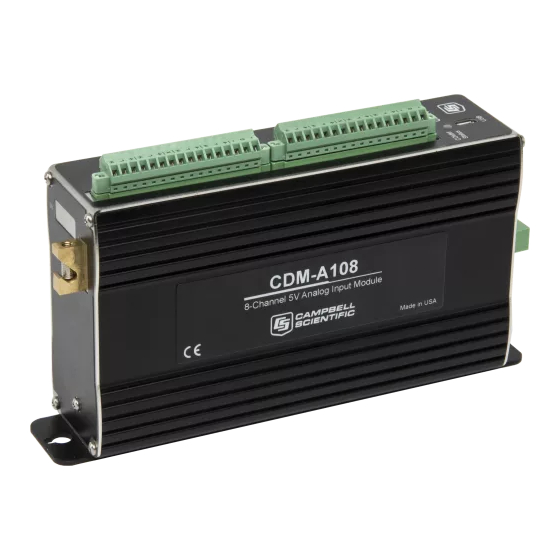
- Page 1 CDM-A100 Series CDM-A108 and CDM-A116 Revision: 11/16 C o p y r i g h t © 2 0 1 5 - 2 0 1 6 C a m p b e l l S c i e n t i f i c ,...
- Page 4 (780) 454-2655. Campbell Scientific (Canada) Corp. is unable to process any returns until we receive this form. If the form is not received within three days of product receipt or is incomplete, the product will be returned to the client at the client’s expense.
- Page 5 Periodically (at least yearly) check electrical ground connections. WHILE EVERY ATTEMPT IS MADE TO EMBODY THE HIGHEST DEGREE OF SAFETY IN ALL CAMPBELL SCIENTIFIC PRODUCTS, THE CLIENT ASSUMES ALL RISK FROM ANY INJURY RESULTING FROM IMPROPER INSTALLATION, USE, OR MAINTENANCE OF TRIPODS, TOWERS, OR ATTACHMENTS TO TRIPODS AND TOWERS SUCH AS SENSORS, CROSSARMS, ENCLOSURES, ANTENNAS, ETC.
- Page 6 PLEASE READ FIRST About this manual Please note that this manual was originally produced by Campbell Scientific Inc. (CSI) primarily for the US market. Some spellings, weights and measures may reflect this origin. Some useful conversion factors: Area: 1 in...
-
Page 8: Table Of Contents
Table of Contents PDF viewers: These page numbers refer to the printed version of this document. Use the PDF reader bookmarks tab for links to specific sections. 1. Introduction ..............1 2. Precautions ..............1 3. Initial Inspection ............1 4. - Page 9 Table of Contents Install Driver for PC Connection ............17 Operating Systems ................18 Configuring the CDM-A100 Series ........... 18 7.3.1 Configuring with the CPIAddModule() Instruction ....18 7.3.2 Configuring with Device Configuration Utility ......18 7.3.3 Configuring with the CPIStatus Table ........19 Datalogger Programming ..............
- Page 10 Table of Contents Adding CDMs with CPIAddModule() ..........B-1 Measuring Thermocouples ............... B-2 Controlling an AM16/32B Multiplexer..........B-3 Measuring Bonded Foil Strain Gages ..........B-4 C. Calculating Network Restrictions ......C-1 Example 1 ..................C-1 Example 2 ..................C-2 Example 3 ..................C-3 D.
- Page 11 Table of Contents...
-
Page 12: Introduction
Protect from water Protect from ESD (electrostatic discharge) • IMPORTANT: Maintain a level of calibration appropriate to the application. Campbell Scientific recommends factory recalibration of the CDM-A100 every three years. Initial Inspection • The CDM-A108 and CDM-A116 ship with the following:... -
Page 13: Quickstart
CDM-A100 Series measurement device. Check that expected cable lengths were received. Contact Campbell Scientific immediately if you find any discrepancies. • Check the operating system version in the CDM-A100, the (p. 32) datalogger, and the SC-CPI (if used), and update as needed. See (p. - Page 14 CDM-A100 Series Select Datalogger Model and Scan Interval (default of 5 seconds is OK for most applications). Click Next. Under the Available Sensors and Devices list, select the Devices folder, then select the CDM-A108. Click to move the selection to the...
- Page 15 CDM-A100 Series When the CDM-A108 is added as a device, a new CDM-A108 tab will appear at the bottom of the Available Sensors and Devices pane. With the CDM-A108 tab selected, select the Sensors | Generic Measurements subfolder. Select Single-Ended Voltage. Click to move the selection to the Selected device window.
- Page 16 CDM-A100 Series Next, provide the attributes of the single-ended measurement. Leave all settings at the default for this example. To learn more about any setting, click Help.
- Page 17 CDM-A100 Series After selecting the measurement, click Wiring Diagram to see how the sensor is to be wired to the datalogger. The wiring diagram can be printed now or after more sensors are added. The CR6 Series tab shows the connection between the CDM-A108 and the datalogger, and the CDM- A108 tab shows the sensor connection to the CDM-A108.
-
Page 18: Overview
CDM-A100 Series 10. Wire the sensors and devices as shown in the wiring diagrams in step 7. Check the output of the sensor in the datalogger support software (p. 32) data display to make sure it is making reasonable measurements. -
Page 19: Wiring Panel Of Cdm-A108 (Left) And Cdm-A116 (Right)
CDM-A100 Series Earth Ground Analog Input Terminals Excitation Terminals Switched 5 V Power Ground Signal Ground Switched 12 V 12 V Out COMM Status LED FIGURE 5-1. Wiring panel of CDM-A108 (left) and CDM-A116 (right) -
Page 20: Analog Input
CDM-A100 Series Power In CPI Ports CPI Port LED Indicators FIGURE 5-2. Power and CPI ports view 5.1.1 Analog Input Analog sensors output a continuous voltage or current signal that varies with the phenomena measured. Sensors compatible with the CDM-A100 output a voltage. -
Page 21: Differential Measurements
CDM-A100 Series 5.1.1.2 Differential Measurements A differential measurement measures the difference in voltage between two input terminals. Use a differential measurement to measure current by using external resistors to convert current to voltage. The CDM-A108 has 8 H/L differential terminals, and the CDM-A116 has 16. -
Page 22: Power Terminals
(p. 32) 5.1.6.2 CPI Port is a proprietary protocol that supports CDMs. Two RJ45 ports labeled (p. 32) CPI enable communications with a Campbell Scientific datalogger and other CDMs. 5.1.7 LED Indicators 5.1.7.1 COMM Status When the CDM-A100 has successfully been configured by a datalogger, the COMM Status will flash green. -
Page 23: Voltage Measurements - Specifications
CDM-A100 Series Voltage Measurements – Specifications Voltage measurements use a 24-bit Analog-to-Digital (A-to-D) converter. One channel at a time is measured in numeric succession. Differential and single- ended channels can be mixed. Terminals Differential Configuration CDM-A108: DIFF 1H/1L – 8H/8L CDM-A116: DIFF 1H/1L –... -
Page 24: Analog Voltage Measurement Accuracy Offsets
48.35 68.06 14.70 34.05 29.40 81.40 12.29 40.72 24.58 134.73 7.42 67.38 14.85 201.40 4.97 100.72 9.93 401.40 2.49 200.72 4.98 801.40 1.25 400.72 2.50 Default settling time of 500 µs. Refers to multiplexing circuitry internal to the CDM-A100 series. -
Page 25: Resistance Measurements - Specifications
CDM-A100 Series Resistance Measurements – Specifications Resistance measurements for four- and six-wire full-bridge and two-, three-, and four-wire half-bridge using voltage excitation or direct resistance measurements using current excitation. Excitation polarity reversal minimizes DC error. Terminals CDM-A108: SE terminals 1-16 DIFF terminals 1H/1L –... -
Page 26: Period Averaging - Specifications
CDM-A100 Series Current Excitation Range: ±2.5 mA Accuracy 0 to 40 °C: ±(0.05% of setting + 2.5 µA) –40 to 70 °C: ±(0.08% of setting + 2.5 µA) –55 to 85 °C: ±(0.1% of setting + 2.5 µA) Resolution: 638 nA Compliance Voltage ±5000 mV... -
Page 27: Switched 12 Vdc
CDM-A100 Series Current Sourcing Limit (each): 200 mA typical, 180 mA minimum Unregulated below 14.5 V. 6.5.2 Switched 12 Vdc Terminals CDM-A108: SW12V-1 CDM-A116: SW12V-1-2 Voltage Output 12.5 ± 0.5 Vdc Current Sourcing Limit (each): 200 mA typical, 180 mA minimum Unregulated below 14.5 V. -
Page 28: Module - Specifications
CDM- A100 via USB. To install the device driver using the Device Configuration Utility , select Peripheral | CDM-A100 Series under Device Type. Click (p. 32) the Install the USB driver link and follow the prompts. -
Page 29: Operating Systems
(p. 32) Open Device Configuration Utility Under Device Type, select Peripheral | CDM-A100 Series. Carefully review the Connect Instructions text provided on the right. With the USB device driver installation complete, connect the supplied USB cable between the USB port on your computer and the USB port on... -
Page 30: Configuring With The Cpistatus Table
Within the ModuleInfo() array index string, the Device Name and CPI Address fields can be edited. This provides a way to rename and readdress a CDM- A100 through Campbell Scientific software. Datalogger Programming Short Cut is the best source for up-to-date datalogger programming code. -
Page 31: Scan Buffers
(p. B-1) 7.4.1 Scan Buffers When CDM-A100 instructions are included in a program, Campbell Scientific recommends setting the BufferOption of the Scan() instruction to a value greater than or equal to two seconds’ worth of scans. For example, if the scan rate is 50 ms (.05 s), set the BufferOption to 40 (2 s ÷... -
Page 32: Connecting Multiple Cdms
CDM-A100 Series The CPI port on CDM-A100 connects directly to the CPI port on the CR6. An SC-CPI device is required to connect to CR800-series, CR1000, and (p. 33) CR3000 dataloggers. Connect the SC-CPI module to these dataloggers by wiring its 12V, G, C1, C2, and C3 terminals to the corresponding 12V, G, C1, C2, and C3 terminals of the datalogger. -
Page 33: Power Connection
CDM-A100 Series Power Connection Connect the power supply to the removable Power connector on the side of the CDM-A100. Power supplies providing voltages from 9.6 to 32 Vdc may be used. NOTE When the supply voltage is below 14.5 Vdc, the voltage on the 12V and SW12V terminals track the power supply. -
Page 34: Cdm Din-Rail Mounting Kit
CDM-A100 Series FIGURE 7-4. CDM DIN-Rail Mounting Kit Follow the steps below to mount the CDM-A100 to a DIN rail. Using a Phillips screwdriver, unfasten both screws on the baseplate of the CDM-A100 and remove the baseplate. Screw the rubber bumper into the bottom outer hole. -
Page 35: Operation
After the measurements are completed, it sends the data to the datalogger for processing. Measurements Because the CDM-A100 series make measurements similar to the CR6 series datalogger, refer to the CR6 Measurement and Control System manual for in- depth measurement details. -
Page 36: Fast Measurements
CDM-A100 Series The panel temperature is measured with the CDM_PanelTemp() instruction, where each thermistor is numbered as shown in FIGURE 5-1, Wiring panel of CDM-A108 and CDM-A116 . In thermocouple measurements, using the (p. 8) panel temperature for the thermocouple-wiring strip will result in more accurate measurements. -
Page 37: Measurement Speed
If the instruction uses excitation, calculate the measurement time separately and add 46 µs for each excitation terminal used. Refer to Example 3 in Appendix C, Calculating Network Restrictions (p. C-1) Refers to multiplexing circuitry internal to the CDM-A100 series. Default settling time, T , is 500 µs, minimum 100 µs. -
Page 38: Sub-Scans
CDM-A100 Series 8.2.1.1 Sub-Scans To measure at rates faster than the maximum scan rate of the datalogger, the SubScan()/NextSubScan instruction pair is added within the datalogger scan. Using this method, the measurement speed is dictated by the SubInterval and Units parameters. -
Page 39: Cpi Network Bit Rate
CDM-A100 Series CRBasic Example 8-2. Measuring VoltSE() in Burst Mode 'Program Example Public BurstSE(1735) DataTable(BurstSETable,True,-1) Sample (1735,BurstSE(),FP2) EndTable BeginProg Scan(1,sec,10,0) ‘Negate the measurement channel to make a burst measurement CDM_VoltSe(CDM_A108,1,BurstSE(),1735,mV5000,-1,False,150,15000,1,0) CallTable BurstSETable NextScan EndProg 8.2.2 CPI Network Bit Rate A CPI network is capable of operating at 1000, 500, 250, 125, or 50 kbps, depending on your network configuration (see Section 7.6, Connecting... -
Page 40: Multiple Devices
If sending the CDM-A100 to Campbell Scientific for calibration or repair, consult first with a Campbell Scientific representative. If the CDM-A100 is malfunctioning, be prepared to perform some troubleshooting procedures while on the phone with Campbell Scientific. Many problems can be resolved with a... -
Page 41: Troubleshooting
CDM-A100 Series telephone conversation. If calibration or repair is needed, the procedure shown Assistance should be followed when sending the product. 10. Troubleshooting 10.1 Troubleshooting – Basic Procedure Check the voltage of the power source at the Power connector. It should be between 9.6 and 32 Vdc. -
Page 42: Comm Status Led
CDM-A100 Series TABLE 10-1. CPIStatus Activity Response Meaning The module is connected to the bus and is making (p. 32) Active measurements according to the datalogger program. The module was present after startup but is no longer Offline responding. The module is or was connected and powered but is not Unused included in the datalogger program. -
Page 43: Glossary
ResourceDVD and at www.campbellsci.com/downloads. The CDM-A100 series is compatible with DevConfig 2.11 and newer. Datalogger Support Software For the purposes of the CDM-A100 series, these include LoggerNet, PC400, PC200W, and RTDAQ. LED (Light Emitting Diode) Lights on all CDM-A100s and related instruments are LEDs. For more... -
Page 44: References
SequentialMode instruction at the beginning of the program. 12. References Campbell Scientific. 2015. CR6 measurement and control system: Operator’s manual. Campbell Scientific. https://s.campbellsci.com/documents/us/manuals/cr6.pdf Campbell Scientific. - Page 45 CDM-A100 Series...
-
Page 46: Importing Short Cut Code Into Crbasic Editor
Appendix A. Importing Short Cut Code Into CRBasic Editor This tutorial shows: • How to import a Short Cut program into a program editor for additional refinement • How to import a wiring diagram from Short Cut into the comments of a custom program Short Cut creates files, which can be imported into CRBasic Editor. -
Page 48: Example Programs
Appendix B. Example Programs B.1 Adding CDMs with CPIAddModule() The following program sets CPI Addresses and Device Names on CDM-A100s with serial numbers 1234, 1235, and 1236 and makes a single-ended measurement on each unit’s SE 1 channel. With slight modifications, this program can be used with the CR800-series, CR1000, and CR3000 dataloggers. -
Page 49: Measuring Thermocouples
Appendix B. Example Programs B.2 Measuring Thermocouples The following program measures 16 thermocouples on a CDM-A116. Because the CDM-A116 can measure 4 thermocouples per terminal strip, this program includes code to use the appropriate reference temperature measurement. CRBasic Example B-2. Measuring Thermocouples 'This program example demonstrates measuring 16 thermocouples on a CDM-A116 'Declare Variables and Units CDMTCRef(16) -
Page 50: Controlling An Am16/32B Multiplexer
Appendix B. Example Programs B.3 Controlling an AM16/32B Multiplexer The following program makes 32 differential measurements through an AM16/32B multiplexer controlled by a CDM-A108 connected to a CR6 datalogger. With slight modifications, this program can be used with the CDM- A116 or CR800 series, CR1000, and CR3000 dataloggers. -
Page 51: Measuring Bonded Foil Strain Gages
B.4 Measuring Bonded Foil Strain Gages The following program example measures four quarter-bridge bonded foil strain gages using Campbell Scientific 4WFBS350 bridge completion modules (pn 20592) on DIFF 1-4. Equivalent resistance for each strain gage circuit is 518.52 Ω (2000 Ω in parallel with 700 Ω) and can be found in the 4WFBS350 manual. - Page 52 Appendix B. Example Programs StdDev(1,Vr1000(2),IEEE4,False) StdDev(1,Strain(3),IEEE4,False) StdDev(1,Vr1000(3),IEEE4,False) StdDev(1,Strain(4),IEEE4,False) StdDev(1,Vr1000(4),IEEE4,False) EndTable DataTable(Table2,True,-1) DataInterval(0,1440,Min,10) Minimum(1,BattV,FP2,False,False) EndTable 'Calibration history table DataTable(CalHist,NewFieldCal,10) SampleFieldCal EndTable 'Main Program BeginProg 'Initialize calibration variables for 'Quarter Bridge Strain, 3-wire 350 ohm with 4WFBS350 TIM measurement 'Vr1000()' CIndex=1 : CAvg=1 : CReps=4 LCount = 1 GFAdj(LCount)=GFsRaw(LCount) Next...
- Page 53 Appendix B. Example Programs...
-
Page 54: Calculating Network Restrictions
Appendix C. Calculating Network Restrictions This section shows some common questions asked while designing networks with CDM-A100s and how to calculate their answers. For all examples, the CDM-A108 or CDM-A116 is connected to a CR6 datalogger. C.1 Example 1 a) How fast can a CDM-A116 make 32 single-ended measurements? The time to make 32 single-ended measurements (which are measurements without input or excitation reversal) is copied below from TABLE 8-1, Multiplexed Analog Voltage Measurement Speed... - Page 55 Appendix C. Calculating Network Restrictions c) What should the scan BufferOption be set to for this example? The general rule is that the number of scan buffers should be enough to hold 2 seconds’ worth of data. With a scan rate of 20 ms, the BufferOption should be 2 s ÷...
- Page 56 Appendix D. Calculating Network Restrictions measurement time − 31 µs −1 − 5 µs = � − T − 180 µs� • 10 repetitions µs/s settle With a measurement time of 5 ms (5000 µs), settling time of 100 µs, and 7 repetitions, f must be greater than 13807 Hz.
- Page 57 Appendix C. Calculating Network Restrictions...
-
Page 58: Analog Voltage Measurement Range And Resolution
Appendix D. Analog Voltage Measurement Range and Resolution TABLE D-1. Analog Voltage Measurement Range and Resolution Typical Effective Resolution Single-Ended Measurements or Differential Differential Measurements with Measurements without Input Reversal Input Reversal Range (Hz) (mV) RMS (µV) bits RMS (µV) bits ±5000 10.350... - Page 59 Appendix D. Analog Voltage Measurement Range and Resolution Typical Effective Resolution Single-Ended Measurements or Differential Differential Measurements with Measurements without Input Reversal Input Reversal Range (Hz) (mV) RMS (µV) bits RMS (µV) bits ±5000 0.769 23.7 1.140 23.2 ±1000 0.162 23.6 0.261 23.0...
- Page 61 Santo Domingo, Heredia 40305 SOUTH AFRICA COSTA RICA • cleroux@csafrica.co.za • info@campbellsci.cc www.campbellsci.co.za www.campbellsci.cc Campbell Scientific Southeast Asia Co., Ltd. Campbell Scientific Ltd. 877/22 Nirvana@Work, Rama 9 Road Campbell Park Suan Luang Subdistrict, Suan Luang District 80 Hathern Road Bangkok 10250...
Need help?
Do you have a question about the CDM-A100 Series and is the answer not in the manual?
Questions and answers