
Related Manuals for Campbell NL116


Summary of Contents for Campbell NL116
- Page 1 NL116 Ethernet and CompactFlash ® Module Revision: 3/15 C o p y r i g h t © 2 0 0 6 - 2 0 1 5 C a m p b e l l S c i e n t i f i c ,...
-
Page 3: Limited Warranty
Limited Warranty “Products manufactured by CSI are warranted by CSI to be free from defects in materials and workmanship under normal use and service for twelve months from the date of shipment unless otherwise specified in the corresponding product manual. (Product manuals are available for review online at www.campbellsci.com.) Products not manufactured by CSI, but that are resold by CSI, are warranted only to the limits extended by the original manufacturer. - Page 4 SCIENTIFIC, INC., phone (435) 227-9000. After an application engineer determines the nature of the problem, an RMA number will be issued. Please write this number clearly on the outside of the shipping container. Campbell Scientific’s shipping address is: CAMPBELL SCIENTIFIC, INC.
- Page 5 Periodically (at least yearly) check electrical ground connections. • WHILE EVERY ATTEMPT IS MADE TO EMBODY THE HIGHEST DEGREE OF SAFETY IN ALL CAMPBELL SCIENTIFIC PRODUCTS, THE CUSTOMER ASSUMES ALL RISK FROM ANY INJURY RESULTING FROM IMPROPER INSTALLATION, USE, OR MAINTENANCE OF TRIPODS, TOWERS, OR ATTACHMENTS TO TRIPODS AND TOWERS SUCH AS SENSORS, CROSSARMS, ENCLOSURES, ANTENNAS, ETC.
-
Page 7: Table Of Contents
Table of Contents PDF viewers: These page numbers refer to the printed version of this document. Use the PDF reader bookmarks tab for links to specific sections. 1. Introduction ..............1 2. Cautionary Statements ..........1 3. Initial Inspection ............2 4. - Page 8 A.1.2 CR1000KD ................A-2 A.1.3 LoggerNet File Control ............A-2 Checking CF Card Integrity ............A-3 Figures 4-1. NL116 attached to a CR1000 .............. 2 4-2. DevConfig setup .................. 3 4-3. Setup screen (EZ View) Datalogger Type ........... 4 4-4.
-
Page 9: Introduction
The first time an NL116 is attached to a datalogger, the datalogger’s memory has to be reorganized to allow room in memory for the IP stack. To avoid the loss of data, collect your data before attaching the NL116 to a datalogger. -
Page 10: Initial Inspection
Restore power to the datalogger. Insert formatted CF card. (For instructions on formatting a CF card, see Appendix A, CF Card Maintenance (p. A-1) NOTE A CF card does not need to be present in order to use the NL116’s IP functionality. FIGURE 4-1. NL116 attached to a CR1000... -
Page 11: Communicating Via Ethernet
4.2.1 Step 1: Configure Datalogger Connect serial cable from PC COM port to the datalogger RS-232 port. Open Campbell Scientific’s Device Configuration Utility (DevConfig). Select the Device Type of the datalogger (CR1000 or CR3000), the appropriate Communication Port, and Baud Rate. Connect to the datalogger. -
Page 12: Step 2: Loggernet Setup
NL116 Ethernet and CompactFlash ® Module The NL116 must be connected to the datalogger before NOTE configuring the datalogger with DevConfig. If it is not connected, the TCP/IP settings will not be displayed. 4.2.2 Step 2: LoggerNet Setup The next step is to run LoggerNet and configure it to connect to the datalogger via the Ethernet port. -
Page 13: Setup Screen (Ez View) Connection Type
NL116 Ethernet and CompactFlash ® Module b. Select IP Port and press Next. FIGURE 4-4. Setup screen (EZ View) Connection Type... -
Page 14: Setup Screen (Ez View) Ip Port Settings
NL116 Ethernet and CompactFlash ® Module Input the datalogger’s IP address and port number and press Next. The IP address and port number are input on the same line separated by a colon. IPv6 addresses will need to be enclosed in square brackets. An IPv4 address may look like 192.168.1.100:6785. -
Page 15: Step 3: Connect
NL116 Ethernet and CompactFlash ® Module d. Input the PakBus Address of the datalogger. FIGURE 4-6. Setup screen (EZ View) Datalogger Settings Press Next until you reach the Communication Setup Summary screen. Press Finish to complete the setup. 4.2.3 Step 3: Connect You are now ready to connect to your datalogger using the LoggerNet Connect screen. -
Page 16: Cf Card Data Retrieval
NL116 Ethernet and CompactFlash ® Module Size: A constant is entered in the Size to define the size of the DataTable on the Card. Size can be defined as a fixed number of records, as auto-allocate, or as the size of the datalogger memory. -
Page 17: Overview
It also has a slot for a Type I or Type II CompactFlash ® (CF) card (3.3 V, 75 mA). The NL116/CF card combination can be used to expand the datalogger memory, transport data/programs from the field site(s) to the office, upload power-up functions, and store JPEG images from a Campbell Scientific camera. -
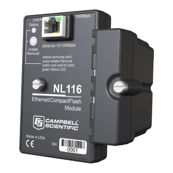
Page 18: Buttons And Status Led
NL116 Ethernet and CompactFlash ® Module Buttons and Status LED There is one red-green-orange LED (light-emitting diode) and two buttons: Initiate Removal and eject. The Status LED indicates the status of the module. The LED will flash red when the CF card is being accessed, solid... - Page 19 Weight: 154 g (5.4 oz) *** The NL116 will automatically negotiate the speed and duplex mode used for the Ethernet link. However, the speed at which data can be transferred to and from a datalogger over the NL116 depends on multiple factors including: the datalogger processor speed, that is, CR1000 vs CR3000 •...
-
Page 20: Operation
Information Services section of the datalogger manual and CRBasic Editor help. 7.1.1 Communicating Over TCP/IP Once the datalogger, the NL116, and LoggerNet have been set up as described in Sections 4.1, Physical Setup , and 4.2, Communicating via Ethernet (p. -
Page 21: Datalogger-To-Datalogger Communication
NL116 Ethernet and CompactFlash ® Module PROGRAM ' CR1000 ' IP_Callback.cr1 ' LoggerNet server Pak Bus Address assumed = 4094 ' PC IP address assumed = 192.168.7.231 ' LoggerNet IPPort "IP Port Used for Call-Back" = 6785 ' LoggerNet IPPort "Call-Back Enabled" is checked ' LoggerNet CR1000 "Call-Back Enabled"... -
Page 22: Http Web Server
NL116 Ethernet and CompactFlash ® Module PROGRAM 'CR1000 'DL-to-Dl_Comms_1.cr1 'Send this program to CR1000 #1 'Remote CR1000 #2 has PBA = 2, IP addr = 192.168.7.125, and port 6785 Public BattVolt,, BattVolt_Remote Public PTemp Public Result1, Result2 Dim Socket as LONG... -
Page 23: Ftp
7.1.3 FTP 7.1.3.1 FTP Server With an NL116 attached, the datalogger will automatically run an FTP server. This allows Windows Explorer to access the datalogger’s file system via FTP. In the FTP world, the “drives” on the datalogger are mapped into directories (or folders). -
Page 24: Ftp Root Directory
NL116 Ethernet and CompactFlash ® Module FIGURE 7-2. FTP root directory FIGURE 7-3. FTP CRD directory... -
Page 25: Ftp Client
Step 1: Configure Datalogger Connect serial cable from PC COM port to datalogger RS-232 port. Open Campbell Scientific’s DevConfig. Select the Device Type of the datalogger (CR1000 or CR3000), the appropriate Communication Port and Baud Rate. Connect to the datalogger. -
Page 26: Telnet
Pinging the datalogger’s IP address may be used to verify communications. 7.1.6 Serial Server With an NL116 attached, the datalogger can be programmed to act as a serial server over the Ethernet port. (A serial server is a device that allows serial communication over a TCP/IP port.) This function may be useful when... -
Page 27: Tcp Modbus
= SerialOut(socket,sent,"",0,100) 7.1.7 TCP ModBus With an NL116 attached, the datalogger can be set up as a TCP ModBus Master or Slave device. For information on configuring the datalogger as a TCP ModBus Master or Slave, see the ModBus section of the datalogger manual. -
Page 28: Program Files
Control. They may also be copied from CPU memory to the card (or from the card to CPU memory) using the CR1000KD. 7.2.3 Power-up Files (Powerup.ini) Users can insert a properly-configured CF card into the NL116, cycle through the datalogger power, and have power-up functions automatically performed. Power-up functions of CompactFlash cards can include: ®... -
Page 29: Applications
NL116 Ethernet and CompactFlash ® Module Comments can be added to the file by preceding them with a single-quote character ('). All text after the comment mark on the same line is ignored. Syntax Syntax allows functionality comparable to File Control in LoggerNet. -
Page 30: Program Execution
NL116 Ethernet and CompactFlash ® Module Command 2 copies the specified program to the designated drive. The • program specified in command 2 will be set to Run Always unless command 6 or 14 is used to set a separate Run Now program. -
Page 31: Camera Files
NL116 Ethernet and CompactFlash ® Module EXAMPLE 7-5. Run Program from CRD: Drive. 'Leave program on CRD:, run always, erase CRD: data files 13,toobigforcpu.cr1,crd: EXAMPLE 7-6. Run Program Always, Erase CF Data. 'Run always, erase CRD: data files 13,pwrup_1.cr1,crd EXAMPLE 7-7. Run Program Now, Erase CF Data. -
Page 32: Program Examples
NL116 Ethernet and CompactFlash ® Module 7.3.2 Program Examples 7.3.2.1 Ring Mode The following program outputs the maximum and minimum of the panel temperature to the card once a second. The first parameter of the CardOut() instruction is 0, which sets the table on the card to ring mode. The second parameter is negative, so all available memory on the card will be allocated to the data table. -
Page 33: Mixed Modes
NL116 Ethernet and CompactFlash ® Module To reset a table after a fill-and-stop table has been filled and stopped, either use the reset button in LoggerNet (Connect | Datalogger | Station Status | Table Fill Times, Reset Tables) or use the CRBasic ResetTable() instruction. -
Page 34: Cf Card Data-Retrieval Details
7.4.1 Via a Communication Link Data can be transferred to a computer via a communication link using one of Campbell Scientific’s datalogger support software packages (for example, PC200W, PC400, LoggerNet). There is no need to distinguish whether the data is to be collected from the CPU memory or a CF card. The software package will look for data in both the CPU memory and the CF card. -
Page 35: Transporting Cf Card To Computer
Do not switch off the datalogger power if a card is present and active. To remove a card, press the Initiate Removal button on the NL116. The datalogger will transfer any buffered data to the card and then power off. The Status LED will turn green when it is OK to remove the card. -
Page 36: Reinserting The Card
FIGURE 7-4. CardConvert 7.4.2.2 Reinserting the Card If the same card is inserted again into the NL116, the datalogger will store all data to the card that has been generated since the card was removed that is still in the CPU memory. If the data tables have been left on the card, new data will be appended to the end of the old files. - Page 37 ® Module 3. When ready to retrieve data, press the NL116 Initiate Removal button to remove the card. The LED will be red while the most-current data is stored to the card and then turn green. Eject the card while the LED is green.
- Page 38 NL116 Ethernet and CompactFlash ® Module...
-
Page 39: Cf Card Maintenance
Appendix A. CF Card Maintenance A.1 Formatting CF Card The CF card can be formatted using 1) Windows Explorer, 2) the CR1000KD, or 3) LoggerNet File Control. A.1.1 Windows Explorer To format card using Windows Explorer: 1) Insert CF card into CF adapter or CF reader. 2) Windows Explorer should identify a drive as a removable disk. -
Page 40: Cr1000Kd
(The datalogger will work with either FAT or FAT32.) A.1.2 CR1000KD To format card using the CR1000KD: 1) Insert CF card into NL116. 2) From the main menu of CR1000KD, choose PCCard. 3) Choose Format Card. 4) Choose Yes to proceed. -
Page 41: Checking Cf Card Integrity
Appendix A. CF Card Maintenance 3) Choose FileControl under the Tools menu of the Connect screen. 4) Highlight CRD. 5) Press Format. 6) Press Yes to confirm. A.2 Checking CF Card Integrity The Windows Check Disk tool can be used to check the integrity of a CF card. To access the Check Disk tool: 1) Insert CF card into CF reader. - Page 42 Appendix A. CF Card Maintenance 5) Navigate to the Tools tab. 6) Press Check. 7) Select Scan and Repair Drive.
- Page 44 • info@campbellsci.com.cn • info@campbellsci.de www.campbellsci.com www.campbellsci.de Campbell Scientific do Brasil Ltda. (CSB) Campbell Scientific Spain, S. L. (CSL Spain) Rua Apinagés, nbr. 2018 ─ Perdizes Avda. Pompeu Fabra 7-9, local 1 CEP: 01258-00 ─ São Paulo ─ SP 08024 Barcelona...
Need help?
Do you have a question about the NL116 and is the answer not in the manual?
Questions and answers