Campbell CELL200 Series Product Manual
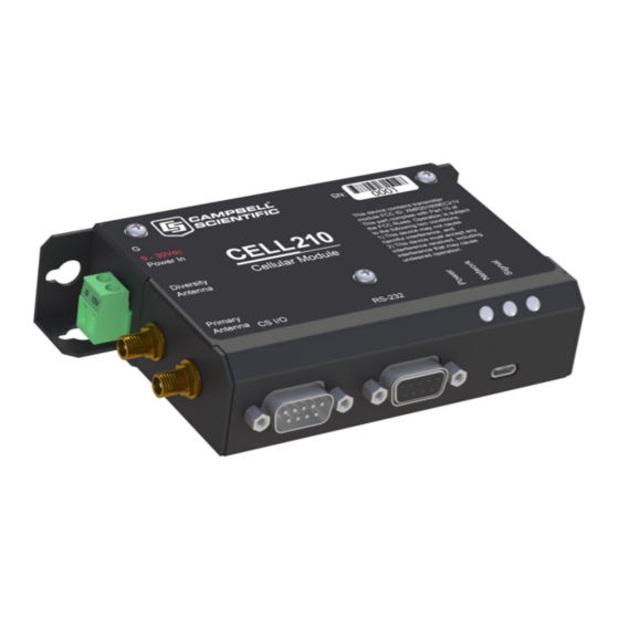
4g lte cellular module
Hide thumbs
Also See for CELL200 Series:
- Product manual (95 pages) ,
- Quick deploy manual (4 pages) ,
- Application note (19 pages)
Table of Contents
Advertisement
Quick Links
Advertisement
Table of Contents

Related Manuals for Campbell CELL200 Series


Summary of Contents for Campbell CELL200 Series
- Page 1 Revision: 08/2022 Copyright © 2018 – 2022 Campbell Scientific CSL I.D - 1281...
- Page 2 Quotations for repairs can be given on request. It is the policy of Campbell Scientific to protect the health of its employees and provide a safe working environment, in support of this policy a “Declaration of Hazardous Material and Decontamination”...
- Page 3 About this manual Please note that this manual was originally produced by Campbell Scientific Inc. primarily for the North American market. Some spellings, weights and measures may reflect this origin. Some useful conversion factors: Area: 1 in (square inch) = 645 mm Mass: 1 oz.
- Page 4 • Periodically (at least yearly) check electrical ground connections. WHILE EVERY ATTEMPT IS MADE TO EMBODY THE HIGHEST DEGREE OF SAFETY IN ALL CAMPBELL SCIENTIFIC PRODUCTS, THE CUSTOMER ASSUMES ALL RISK FROM ANY INJURY RESULTING FROM IMPROPER INSTALLATION, USE, OR MAINTENANCE OF TRIPODS, TOWERS, OR ATTACHMENTS TO TRIPODS AND TOWERS...
-
Page 5: Table Of Contents
1. Cellular communications 2. Precautions 3. Initial inspection 4. Pre-installation 4.1 Establish cellular service 4.1.1 Campbell Scientific cellular data service 4.1.2 Other service providers 4.2 Install the SIM card 4.3 Konect PakBus Router setup 4.3.1 Get started 4.3.2 Set up Konect PakBus Router 5. - Page 6 8.3.2 Module power connections 8.3.3 Antenna connections 8.4 CELL200 series and data logger configuration 8.4.1 Integrated mode option 8.4.2 Non-integrated mode option 8.4.2.1 Configure CELL200 series 8.4.2.2 Configure data logger 8.4.2.3 Set up hardware 8.4.2.4 Set up LoggerNet 8.4.2.5 Test the connection 8.4.3 Serial server mode option...
- Page 7 Appendix A. Controlling power to the CELL200 series Appendix B. Configuring settings and retrieving status information with the CRBasic program B.1 Using the SetSetting() instruction Appendix C. Updating the operating system and firmware C.1 Using the web interface (cell.linktodevice.com) C.2 Using Device Configuration Utility Appendix D.
-
Page 8: Cellular Communications
AT&T ended support of their 3G network service on February 22, 2022. To continue operation the CELL200 series requires operating system 2.030 or newer. Use the web interface to find the CELL200 series OS version on the OS Date field of the Status Tab. See Updating the operating system and firmware (p. -
Page 9: Precautions
An authorized technician shall verify that the installation and use of this product is in accordance with the manufacturer’s instructions, recommendations and intended use. Although the CELL200 series is rugged, it should be handled as a precision instrument. Follow local regulations (see Compliance in Specifications [p. -
Page 10: Establish Cellular Service
T-Mobile, Vodafone, Telstra, and over 600 other providers worldwide. When this cellular service is purchased with the module, the module will come pre-provisioned with the required SIM card and APN. If you have already purchased the CELL200 series, call Campbell Scientific to set up service. -
Page 11: Install The Sim Card
PIN is to install the SIM card in a mobile phone and use the device settings. The CELL200 series requires a Micro-SIM (3FF) (6 position / contacts); a smartcard that securely stores the key identifying a mobile subscriber. You should only need to install the SIM card once in the life of the module. -
Page 12: Konect Pakbus Router Setup
4.3 Konect PakBus Router setup For better security, we recommend using Konect PakBus® Router with a private dynamic IP address. This method allows only incoming PakBus communications. No other incoming communications are supported. However, all forms of outbound communications from the data logger are supported, including but not limited to PakBus, email, and FTP. -
Page 13: Set Up Konect Pakbus Router
4.3.2 Set up Konect PakBus Router 1. Sign in to www.konectgds.com using your Passport ID and Password found in the two received emails. Once logged in, you will be at the Welcome page. CELL200-Series 4G LTE Cellular Module 6... - Page 14 2. Click Devices and services on the command bar to the left and select Redeem PakBus Router Code. Enter your complimentary Router Code found on the included card with your cellular-enabled device and click Submit. 3. The next screen shows the assigned DNS address and Port for the router. Enter a TCP Password and select a unique PakBus Address for your data logger.
-
Page 15: Overview
5. To edit settings at a later date, click devices and services on the command bar and select Manage PakBus Routers. NOTE: The DNS address and Port number, assigned when your account was setup, cannot be edited. 5. Overview The CELL200-series modules may be configured in one of five ways, depending on the data logger, communications type, and needs of the user. - Page 16 When a client connects to the listening port, the CELL200 series will be in "Serial Server" mode, as described earlier. When no client is connected to the listening port, the CELL200 series will be in "Serial Client" mode, as described earlier, and all data on the active port will be sent and received through the initiated TCP client socket connection.
-
Page 17: Quickstart (Integrated Mode)
The second sticker will show the static IP address. Campbell Scientific cellular modules configured with a private dynamic IP address will have one sticker on the module. It will show the module phone number and data plan. -
Page 18: Modules Using Konect Pakbus Router (Private Dynamic Ip)
Wiring and connections (p. 29). 3. If not connecting through CS I/O, provide power to the CELL200 series. The data logger provides power through the CS I/O port. USB power is not sufficient to power the CELL200 series; 12 V is required. -
Page 19: Configure Data Logger
6.1.2 Configure data logger 1. Connect to your data logger by using Device Configuration Utility. 2. On the Datalogger tab, change the data logger PakBus Address and PakBus/TCP Password to match the values entered in the Konect PakBus Router setup. The PakBus/TCP Password will make the data logger authenticate any incoming or outgoing PakBus/TCP connection. - Page 20 12. Click Connect to reconnect in the Device Configuration Utility. 13. (Optional) By default, the CELL200 series will accept incoming communications from any IP address. This can be a security risk. You may specify up to four IP addresses, with wild cards, to limit connections to only those trusted sources.
-
Page 21: Set Up Loggernet
In the Settings Editor > Network Services tab, next to the Trusted Hosts field, click Edit and Add your trusted IP addresses, one at a time. 14. Click Apply to save the changes. Verify the settings in the summary window. (Recommended) Save a copy of the settings to a file on the computer. - Page 22 NOTE: PakBus data loggers include the following models: GRANITE-series, CR6, CR3000, CR1000X, CR800-series, CR300-series, CR1000, and CR200(X)-series. 3. Add a data logger to the pbRouter. 4. From the Entire Network, on the left side, select the IPPort. Enter the Konect PakBus Router DNS address and port number as noted in the Konect PakBus Router setup (Set up Konect PakBus Router...
- Page 23 5. Leave the default settings for the PakBusPort. PakBus Port Always Open should not be checked. In the TCP Password field enter the TCP Password; this must match the value entered in the Konect PakBus Router setup and LoggerNet setup. CELL200-Series 4G LTE Cellular Module 16...
- Page 24 6. For PakBus data loggers, select the pbRouter in the Network Map and set the PakBus Address to 4070. 7. For PakBus data loggers, select the data logger in the Network Map and set the PakBus Address to match that of the data logger (default address in the data logger is 1). If a PakBus Encryption Key was entered during data logger setup, also enter it here.
-
Page 25: Test The Connection
6.1.4 Test the connection After the Network Map has been configured, test the cellular connection by using the Connect screen as shown in the following image. Click on the appropriate station and click Connect to initiate a call to the data logger. TIP: The connection time is subject to many external factors. -
Page 26: Configure Data Logger
Wiring and connections (p. 29). 3. If not connecting through CS I/O, provide power to the CELL200 series. The data logger provides power through the CS I/O port. USB power is not sufficient to power the CELL200 series; 12 V is required. - Page 27 6. On the Cellular tab, enter the APN provided by your cellular provider. 7. (Optional) By default, the CELL200 series will accept incoming communications from any IP address. This can be a security risk. You may specify up to four IP addresses, with wild cards, to limit connections to only those trusted sources.
-
Page 28: Set Up Loggernet
In the Device Configuration Utility go to the Settings Editor then Network Services. Next to the Trusted Hosts field, click Edit and Add your trusted IP addresses, one at a time. 8. Click Apply to save the changes. 6.2.3 Set up LoggerNet The LoggerNet Network Map is configured from the LoggerNet Setup screen. - Page 29 4. Select the IPPort in the Network Map. Enter the CELL200 series IP address and port number. The IP address and port number are input in the Internet IP Address field separated by a colon. Preceding zeros are not entered in the Internet IP Address (for example, 070.218.074.247 is entered as 70.218.74.247).
-
Page 30: Test The Connection
6. For PakBus data loggers, select the data logger in the Network Map and set the PakBus Address to match that of the data logger (default address in the data logger is 1). If a PakBus Encryption Key was entered during data logger setup, also enter it here. Click Apply to save the changes. -
Page 31: Specifications
If the connection fails, a Communications Failure message will be displayed. 7. Specifications Data Logger Compatibility The CELL200 series is compatible with the GRANITE-series, CR6, CR3000, CR1000X, CR800-series, CR300-series, CR1000, CR200(X) series, CR5000, CR10X, CR10X-PB, CR510, CR510-PB, CR23X, and CR23X-PB. See Module communications connections (p. - Page 32 RF Connectors 2 SMA antenna connectors (primary and diversity) Power Operating Voltage: 10 to 30 VDC Low Power Mode: 300 μA Typical Idle: 14 mA @ 12 VDC Typical Active: 39 mA @ 12 VDC (CELL205, CELL215, CELL220, CELL225) 25 mA @ 12 VDC (CELL210) Size ...
-
Page 33: Installation
8.4.2 Non-integrated mode option 8.4.3 Serial server mode option 8.4.4 Serial client mode option 8.4.5 Serial server/client mode option 8.1 Base station requirements A computer running Campbell Scientific LoggerNet software with access to the Internet is needed. CELL200-Series 4G LTE Cellular Module 26... -
Page 34: Data Logger Site Equipment
CPI/RS-232 port. Antenna — the following antennas are available from Campbell Scientific. Contact Campbell Scientific for help in determining the best antennas for your application. 2 dBd 4G/3G Omnidirectional Antenna: An omnidirectional antenna with mounting bracket that is ideally suited for use with 4G and 3G cellular gateways. The mounting bracket attaches to a mast or crossarm, and it serves as the antenna ground plane. - Page 35 jack. The antenna includes a mount/U-bolt assembly for attaching the antenna to a mast, post, or crossarm up to 3.8 cm (1.5 in) in diameter. The 38485 antenna is a wideband, dual-port, directional-panel antenna with slant 45 polarization that covers US LTE700/Cellular/PCS/AWS/MDS and global GSM900/GSM1800/UMTS/LTE2600 bands.
-
Page 36: Wiring And Connections
NOTE: When antennas are located away from the CELL200 series, keep the cables as short as possible to prevent the loss of antenna gain. Route the cables to protect them from damage and so they will not be snagged or pulled on. Avoid binding or sharp corners in the cable routing. - Page 37 Table 8-1: CELL200 series data logger compatibility chart Connecting to CELL200 series Connecting to CELL200 series Data logger model via its CS I/O port via its RS- 232 port RS-232 null modem cable, or CR300 C-port to RS-232 cable (PPP or serial server)
- Page 38 Figure 8-3 (p. 32) illustrate the most common communications connections between a data logger and a CELL200 series. CS I/O connection using an SC12 cable The SC12 is used to connect the module to a data logger CS I/O port.
-
Page 39: Module Power Connections
62) provides an example CRBasic program using the IPNetPower() instruction to control power to the CELL200 series. This functionality is available in the CR300 series (all operating systems), the CR6 series with operating system 09.00 or greater, and the CR1000X with operating system 03.00 or greater. To control power in these data loggers with older operating systems or any CR1000, CR800 series, or CR3000, you will need to use a SW12V port on the data logger and communicate over RS-232. -
Page 40: Antenna Connections
PPPClose "deep CR1000, CR800 series, and CR3000 CRBasic programs require before the sleep" PPPOpen "wakeup" command and before the command. The USB port provides power for module configuration, but is not sufficient for normal operation. 8.3.3 Antenna connections Use of a diversity antenna can improve system performance. It is required in 4G networks, but not 2G or 3G. - Page 41 Diversity antennas are not required for 2G/3G connections; however, they are highly recommended in order to get the most reliable connection, especially in areas of low coverage. Identical or very similar antennas should also be used for the best results. For 4G networks, the second antenna operates as a MIMO (multiple input, multiple output ) antenna, providing a second receive path.
-
Page 42: Cell200 Series And Data Logger Configuration
10) describes setting up the CELL200 series in integrated mode with its default settings. If the module is not in its default settings, the settings in the CELL200 series must match those in the data logger for integrated mode to work. This includes the SDC Address for CS I/O communications or the RS-232 Baud Rate for RS 232 communications. -
Page 43: Configure Cell200 Series
NOTE: This section only applies to CR3000, CR1000 and CR800-series users. 8.4.2.1 Configure CELL200 series 1. Connect a USB cable between your module and computer. 2. Connect the cellular antenna, if it is not already connected. When using a MIMO antenna with multiple cellular connections, connect the primary cable to Cellular and the secondary to Diversity. -
Page 44: Set Up Hardware
Wiring and connections (p. 29). 3. If not connecting through CS I/O, provide power to the CELL200 series. The data logger provides power through the CS I/O port. USB power is not sufficient to power the CELL200 series; 12 V is required. - Page 45 4. Select the IPPort in the Network Map. Enter the CELL200 series IP address (public static IP) or the Konect PakBus Router DNS address (private dynamic IP), along with the port number. The address and port number are input in the Internet IP Address field separated by a colon.
- Page 46 5. Leave the default settings for the PakBusPort. PakBus Port Always Open should not be checked. Enter the TCP Password; this must match the value entered in the Konect PakBus Router setup and LoggerNet setup. 6. Select the pbRouter in the Network Map and set the PakBus Address to 4070. CELL200-Series 4G LTE Cellular Module 39...
-
Page 47: Test The Connection
7. Select the data logger in the Network Map and set the PakBus Address to match that of the data logger (default address in the data logger is 1). If a PakBus Encryption Key was entered during data logger setup, also enter it here. Click Apply to save the changes. 8.4.2.5 Test the connection After the Network Map has been configured, test the cellular connection by using the Connect screen as shown in the following image. -
Page 48: Serial Server Mode Option
If the connection is successful, the connectors icon at the bottom of the screen will come together and clock information from the data logger will be displayed in the Station Date/Time field. If the connection fails, a Communications Failure message will be displayed. 8.4.3 Serial server mode option In serial server mode, the module receives IP communications over the cellular network and converts those to serial communications to pass on to the data logger. -
Page 49: Configure Cell200 Series
8.4.3.1 Configure CELL200 series To set up the CELL200 series in serial server mode: 1. Connect a USB cable between your module and computer. 2. Connect the cellular antenna, if it is not already connected. When using a MIMO antenna with multiple cellular connections, connect the primary cable to Cellular and the secondary to Diversity. - Page 50 9. (Optional) By default, the CELL200 series will accept incoming communications from any IP address. This can be a security risk. You may specify up to four IP addresses, with wild cards, to limit connections to only those trusted sources.
-
Page 51: Configure Data Logger
Wiring and connections (p. 29). 3. If not connecting through CS I/O, provide power to the CELL200 series. The data logger provides power through the CS I/O port. USB power is not sufficient to power the CELL200 series; 12 V is required. -
Page 52: Set Up Loggernet
CR1000X, CR800-series, CR300-series, CR1000, and CR200(X)-series. 3. Add a data logger. 4. Select the IPPort in the Network Map. Enter the CELL200 series IP address (public static IP), along with the port number. The address and port number are input in the Internet IP Address field separated by a colon. -
Page 53: Test The Connection
5. For PakBus data loggers, leave the default settings for the PakBusPort. PakBus Port Always Open should not be checked. If used, enter the TCP Password. 6. For PakBus data loggers, select the data logger in the Network Map and set the PakBus Address to match that of the data logger (default address in the data logger is 1). -
Page 54: Serial Client Mode Option
If the connection fails, a Communications Failure message will be displayed. 8.4.4 Serial client mode option This mode requires CELL200 series operating system 2.00 or newer. Find the CELL200 series OS version in the OS Date field of the Status Tab. For more information, see... -
Page 55: Configure Cell200 Series
10). 8.4.4.1 Configure CELL200 series To set up the CELL200 series in serial client mode: 1. Connect a USB cable between your module and computer. 2. Connect the cellular antenna, if it is not already connected. When using a MIMO antenna with multiple cellular connections, connect the primary cable to Cellular and the secondary to Diversity. - Page 56 7. Select the Serial Mode Setup tab. 8. Enter the URL and Port Number of the server/device that the module will connect to. 9. (Optional) Select Always Open for the Timeout . CELL200-Series 4G LTE Cellular Module 49...
-
Page 57: Configure Data Logger (Optional)
10. (Optional) In this mode, an Automated Power Schedule can be setup to save on battery life or on cellular charges. Go to the Settings then Serial Mode Setup tab. Enter a Start (power- on) Time, On duration, and Repeat cycle. The modem automatically turns off at midnight. -
Page 58: Set Up Hardware
Wiring and connections (p. 29). 3. If not connecting through CS I/O, provide power to the CELL200 series. The data logger provides power through the CS I/O port. USB power is not sufficient to power the CELL200 series; 12 V is required. -
Page 59: Test The Connection
3. Select the PakBusTcpServer in the Network Map. PakBus Port Always Open should be checked. 4. Select the data logger in the Network Map. Select Call-Back Enabled; the box should have a check. 8.4.4.5 Test the connection After the Network Map has been configured, test the cellular connection by using the Connect screen as shown in the following image. -
Page 60: Serial Server/Client Mode Option
In serial server mode, all data on the active port (RS-232 or CS I/O) will be routed through the listening port. When no client is connected to the listening port, the CELL200 series will be in CELL200-Series 4G LTE Cellular... -
Page 61: Configure Cell200 Series
10). 8.4.5.1 Configure CELL200 series To set up the CELL200 series in serial server/client mode: 1. Connect a USB cable between your module and computer. 2. Connect the cellular antenna, if it is not already connected. When using a MIMO antenna with multiple cellular connections, connect the primary cable to Cellular and the secondary to Diversity. - Page 62 6. Select the Serial Mode Setup tab. 7. Set Server (Listening) Port Number. Default is 3001. This is entered along with the IP address as part of the LoggerNet configuration. 8. Enter the URL and Port Number that the module will connect with. 9.
- Page 63 11. (Optional) By default, the CELL200 series will accept incoming communications from any IP address. This can be a security risk. You may specify up to four IP addresses, with wild cards, to limit connections to only those trusted sources.
-
Page 64: Configure Data Logger
Wiring and connections (p. 29). 3. If not connecting through CS I/O, provide power to the CELL200 series. The data logger provides power through the CS I/O port. USB power is not sufficient to power the CELL200 series; 12 V is required. -
Page 65: Test The Connection
From the LoggerNet toolbar, click Main > Setup and configure the Network Map as described in the following steps: 1. Select Add Root > PakBusTcpServer. 2. Add a data logger to the PakBusTcpServer. 3. Select the PakBusTcpServer in the Network Map. PakBus Port Always Open should be checked. -
Page 66: Operation And Maintenance
9. Operation and maintenance 9.1 Ports The CS I/O port is the main port used with Campbell Scientific data loggers. Its function is described throughout this manual. The RS-232 port can also be used with Campbell Scientific data loggers through a null modem cable (or CPI/RS-232 RJ45 to DB9 cable for the CR1000X and CR6 series). -
Page 67: Led Indicator Lights
9.2 LED indicator lights When your CELL200-series module is connected to power and an antenna, there is a specific pattern to the lights to indicate its operation mode as described in LED Indicator Lights (p. 60). Table 9-1: LED Indicator Lights ... -
Page 68: Signal Strength
9.3.1 Signal strength Signal strength is how strong the received signal is. The closer your CELL200 series is to the cellular tower, the more signal the antenna will pick up. Signal strengths are lower the farther away from the tower the CELL200 series is. -
Page 69: Appendix A. Controlling Power To The Cell200 Series
Appendix A. Controlling power to the CELL200 series This example shows how to control power to the CELL200 series by using the CRBasic IPNetPower() TimeIsBetween() instruction. The program uses the instruction to power the CELL200 series for 15 minutes every 60 minutes between 9:00 a.m. and 5:00 p.m. - Page 70 CRBasic Example 1: Turn CELL200 series ON and OFF under data logger control 'Main Program BeginProg 'Main Scan Scan(5,Sec,1,0) 'Default Data Logger Battery Voltage measurement 'BattV' Battery(BattV) 'Default Wiring Panel Temperature measurement 'PTemp_C' PanelTemp(PTemp_C,60) 'Between the hours of 9:00 and 17:00, turn the CELL200 series...
-
Page 71: Appendix B. Configuring Settings And Retrieving Status Information With The Crbasic Program
Appendix B. Configuring settings and retrieving status information with the CRBasic program B.1 Using the SetSetting() instruction NOTE: This functionality is available in the CR1000X, CR300-series, and CR6 dataloggers only. Downloadable example programs are available at www.campbellsci.eu/downloads/cell200- . The CELL2XX-SetSettings example shows how to set up the cellular example-programs ... -
Page 72: Appendix C. Updating The Operating System And Firmware
The CELL200 series itself uses two operating systems. The first is the Campbell Scientific CELL200 series operating system. We will refer to that as the CELL200 series OS. The second is contained in the cellular radio module; we will refer to that one as the module firmware. One or both may need to be updated from time to time. - Page 73 Open a web browser and enter the module static IP address. 5. Every 14 days, the module automatically checks for a CELL200 series OS update. When a new OS is available you will see a red notification in the Version field of the Status Tab.
- Page 74 6. Select the OS Update Tab. Clicking the Apply Update button will retrieve the CELL200 series OS from the Campbell Scientific website and begin the update process. If you already downloaded the OS from the Campbell Scientific website to you computer you can click the Send File button and follow the prompts.
-
Page 75: Using Device Configuration Utility
5. Connect to your data logger by using Device Configuration Utility. 6. When a new CELL200 series OS is available, in the Settings Editor on the Cellular Tab you will see a field called Cellular OS Update Pending. This field does not appear unless an update is available. - Page 76 9. Apply to save your changes. CELL200-Series 4G LTE Cellular Module 69...
-
Page 77: Appendix D. Cellular Module Terminal Functionality
Appendix D. Cellular module terminal functionality This appendix discusses the terminal functionality of the CELL200-series modules. This functionality requires a data logger with a CS I/O port. To use the terminal functionality of the module, you must enable the terminal port. To do this: 1. -
Page 78: Using Cell Modem Terminal Functionality
71) shows how to set up an attached CELL200-series module using the terminal functionality in the module. It also illustrates how to use the same functionality to retrieve status information from the CELL200 series and put the module into low power mode. Downloadable example programs are available at See the CELL2XX- www.campbellsci.eu/downloads/cell200-example-programs. - Page 79 Corresponds with the APN setting in the cellular module web interface. show arev Returns the alternate or subversion revision of the CELL200 series show band Returns the band number the modem is using to connect to the cellular network.
- Page 80 show diversity Displays the current setting of cellular module antenna configuration. Results are Disabled or Enabled . Corresponds with the Diversity Antenna field in the cellular module web interface. show ecio Returns the modem 3G network signal quality (ECIO). show euiccid Returns the modem EUICCID (Embedded SIM identification) number.
- Page 81 Returns the name of the cellular provider or network operator the modem is connected to. show osdate Returns the build date and alternate version of the CELL200 series show osupdate description Returns a description of the newer operating system for the user to review before installing.
- Page 82 Returns the revision of the CELL200 series OS. show roaming Displays the current setting for the modem roaming capabilities. Returned values are Auto and Disabled . Corresponds to the Roaming setting in the cellular module web interface show rsrp Returns the modem LTE network signal strength (RSRP).
-
Page 83: Set Commands
show state Returns the modem state in English. Values returned could include (but not limited to) "Power off.", "Powering up.", "Powered up.", "SIM authorized.", "Setting baud rate.", "Waiting for baud rate.", "Baud rate set.", "Baud rate failure.", "Power off. Waiting for retry.", "Powered up. - Page 84 set apn ### Sets the APN (Access Point Name) in the device. Corresponds to the APN setting in the modem web configuration interface. ### is a string the corresponds to the APN issued by the cellular provider when the cellular account was created. set baud ### Sets the modem baud rate for the RS-232 port.
-
Page 85: Action Commands
set power duration ### Sets the on duration, in minutes. ### is a number. Accepted values are: 5, 10, 15, 20, 25, 30, 35, 40, 45, 50, 60, 120, 180, 240, 300, 360, 420, 480, 540, 600, 660, 720, 780, 840, 900, 960, 1020, 1080, 1140, 1200, 1260, 1320, 1380, and 1439. - Page 86 check update Starts the process that checks for both a new CELL200-series operating system, and module firmware. clear logs Resets all the logs in the modem. clear usage Resets the usage counts in the modem. deep sleep Puts the modem into low power mode. Modem will not respond across the cellular network.
-
Page 87: Appendix E. Verizon Wireless And At&T
Appendix E. Verizon Wireless and AT&T NOTE: Campbell Scientific can provide Verizon Wireless or AT&T service. This is the simplest way to set up your module on the Verizon Wireless or AT&T network. See Campbell Scientific cellular data service (p. 3). -
Page 88: At&T
AT&T 4G LTE CAT-1 coverage at the data logger site. For a coverage map refer to: www.att.com/maps/wireless-coverage.html AT&T 4G LTE private dynamic IP account in conjunction with Campbell Scientific’s Konect Router Service. (An AT&T 4G LTE static unrestricted IP account can also be used. However, AT&T charges $3/month/device for the static IP account.) -
Page 89: Appendix F. Cellular Module Regulatory Information
WARNING: Changes or modifications to this device not expressly approved by Campbell Scientific could void the user’s authority to operate this equipment. F.2 RF exposure... - Page 90 Directive 2014/53/EU” (RED Directive). The CELL215 displays the CE mark. WARNING: Changes or modifications to this device not expressly approved by Campbell Scientific could void the user’s authority to operate this equipment. WARNING: This product is only to be installed by qualified personnel.
- Page 91 WARNING: Changes or modifications to this device not expressly approved by Campbell Scientific could void the user’s authority to operate this equipment. WARNING: This product is only to be installed by qualified personnel. The Declaration of Conformity made under Regulation 2017 No. 1206 is available for viewing at: www.campbellsci.eu/cell215.
- Page 92 Campbell Scientific Regional Offices Australia France Thailand Location: Garbutt, QLD Australia Location: Vincennes, France Location: Bangkok, Thailand Phone: 61.7.4401.7700 Phone: 0033.0.1.56.45.15.20 Phone: 66.2.719.3399 Email: info@campbellsci.com.au Email: info@campbellsci.fr Email: info@campbellsci.asia Website: www.campbellsci.com.au Website: www.campbellsci.fr Website: www.campbellsci.asia Brazil Germany Location: São Paulo, SP Brazil...
Need help?
Do you have a question about the CELL200 Series and is the answer not in the manual?
Questions and answers