Table of Contents
Advertisement
Quick Links
Advertisement
Table of Contents

Related Manuals for Campbell GRANITE VOLT Series


Summary of Contents for Campbell GRANITE VOLT Series
- Page 1 09/2019 Copyright © 2019 Campbell Scientific, Inc.
- Page 2 Limited warranty “Products manufactured by CSI are warranted by CSI to be free from defects in materials and workmanship under normal use and service for twelve months from the date of shipment unless otherwise specified in the corresponding product manual. (Product manuals are available for review online at www.campbellsci.com.) Products not manufactured by CSI, but that are resold by CSI, are warranted only to the limits extended by the original manufacturer.
- Page 3 Campbell Scientific reserves the right to refuse service on products that were exposed to contaminants that may cause health or safety concerns for our employees.
- Page 4 Periodically (at least yearly) check electrical ground connections. WHILE EVERY ATTEMPT IS MADE TO EMBODY THE HIGHEST DEGREE OF SAFETY IN ALL CAMPBELL SCIENTIFIC PRODUCTS, THE CUSTOMER ASSUMES ALL RISK FROM ANY INJURY RESULTING FROM IMPROPER INSTALLATION, USE, OR MAINTENANCE OF TRIPODS, TOWERS, OR...
-
Page 5: Table Of Contents
Table of contents 1. Introduction 2. Precautions 3. Initial inspection 4. Measurement quickstart using SURVEYOR 5. Programming quickstart using SURVEYOR 6. Programming quickstart using Short Cut 7. Overview 7.1 Wiring panel overview 7.1.1 Analog input 7.1.1.1 Single-ended measurements 7.1.1.2 Differential measurements 7.1.1.3 Period averaging 7.1.2 Voltage and current excitation 7.1.3 Switched voltage output... - Page 6 8.5.2 Switched 12 VDC 8.5.3 Switched 5 VDC 8.6 Module 8.6.1 Communications 8.6.2 System 8.6.3 Power requirements 8.6.4 Compliance 8.6.5 Physical attributes 9. Installation 9.1 Install driver for computer connection 9.2 Operating systems 9.3 Configuring VOLT 100 series 9.3.1 Configuring with SURVEYOR 9.3.2 Configuring with the CPIAddModule() instruction 9.3.3 Configuring with Device Configuration Utility 9.3.4 Configuring with CPIStatus table...
- Page 7 10.4.1.1 Sub-scans 10.4.1.2 Burst measurements 10.4.2 CPI network bit rate 10.5 Multiple devices 10.6 Switched voltage output 11. Maintenance and calibration 12. Troubleshooting 12.1 CPIStatus table 12.2 COMM status LED 12.3 CPI port LEDs 12.4 Replacing a GRANITE measurement module Appendix A.
-
Page 8: Introduction
Protect from over-voltage Protect from water Protect from ESD (electrostatic discharge) IMPORTANT: Maintain a level of calibration appropriate to the application. Campbell Scientific recommends factory recalibration of the VOLT 100 series every three years. 3. Initial inspection The VOLT 100 series ships with the following: ... -
Page 9: Measurement Quickstart Using Surveyor
4. Measurement quickstart using SURVEYOR Campbell Scientific SURVEYOR software is an easy way to quickly see measurement results and store data from the VOLT 100 series. The module configuration can be saved on the computer or exported as a CRBasic data logger program. SURVEYOR is available as a download from www.campbellsci.com/cs-surveyor. - Page 10 9. Add Measurement(s). For this exercise, add a Type-T differential thermocouple on DIFF1. VOLT 100 series...
- Page 11 10. Wire the sensor according to the given wiring diagram. 11. Complete the rest of the form and Apply to save the configuration. VOLT 100 series...
-
Page 12: Programming Quickstart Using Surveyor
5. Programming quickstart using SURVEYOR Campbell Scientific SURVEYOR is an easy way to generate a simple CRBasic program for your Campbell Scientific data acquisition system. 1. Configure the VOLT 100 series for measurements, see Measurement quickstart using SURVEYOR (p. -
Page 13: Programming Quickstart Using Short Cut
2. Select File > Export Datalogger Program then select the data logger you will be connecting the VOLT 100 series to. For this example, we'll select GRANITE 6. 3. By default, the CRBasic program will be saved in C:\Users\username\Documents\SURVEYOR. 6. Programming quickstart using Short Cut Short Cut is an easy way to program the GRANITE data acquisition system to measure a sensor and assign wiring terminals. - Page 14 4. In the Available Sensors and Devices box, type Type T. You can also locate the thermocouple in the Sensors > Temperature folder. Double click Type T Thermocouple. Type the number of type T thermocouples connected to the VOLT 100 series. The temperature defaults to degree C.
- Page 15 5. Click on the Wiring tab to see how the sensor is to be wired to the VOLT 100 series. Click OK after wiring the thermocouple. 6. Repeat steps four and five for other sensors you want to measure. Click Next. 7.
-
Page 16: Overview
8. Select the measurement and its associated output option. 9. Click Finish and save the program. Send the program just created to the GRANITE data logger if it is connected to the computer. 10. If the thermocouple is connected to the VOLT 100 series, check the output of the thermocouple in the data logger support software data display in LoggerNet or RTDAQ to make sure it is making reasonable measurements. -
Page 17: Wiring Panel Overview
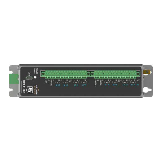
7.1 Wiring panel overview CAUTION: To avoid damage to sensors and devices, ensure that each removable wiring-terminal strip is connected to the VOLT 108 and VOLT 116 in the proper location before applying power. Each strip is keyed identically. FIGURE 7-1. VOLT 108 Wiring panel FIGURE 7-2. -
Page 18: Analog Input
FIGURE 7-3. Power and CPI ports view (left) and ground lug view (right) 7.1.1 Analog input Analog sensors output a continuous voltage or current signal that varies with the phenomena measured. Sensors compatible with the VOLT 100 series output a voltage. Current output can be made compatible with a resistive shunt. -
Page 19: Differential Measurements
in blue. The VOLT 108 has 16 SE terminals, and the VOLT 116 has 32. For example, single-ended channel 1 is comprised of terminals 1 and ⏚. 7.1.1.2 Differential measurements A differential measurement measures the difference in voltage between two input terminals. Use a differential measurement to measure current by using external resistors to convert current to voltage. -
Page 20: Grounding Terminals
7.1.4 Grounding terminals Proper grounding lends stability and protection to a data acquisition system. It is the easiest and least expensive insurance against data loss — and often the most neglected. The following terminals are provided for connection of sensor and VOLT 100 series grounds: Signal Ground (⏚) –... -
Page 21: Led Indicators
CPI is a proprietary protocol that supports GRANITE Measurement Modules. Two RJ45 ports labeled CPI enable communications with a Campbell Scientific data logger and other GRANITE Measurement Modules. 7.1.7 LED indicators 7.1.7.1 COMM status When the VOLT 100 series has successfully been configured by a data logger, the COMM Status LED will flash green. - Page 22 Accuracy 0 to 40 °C: ±(0.04% of Reading + Offset –40 to 70 °C: ±(0.06% of Reading + Offset –55 to 85 °C: ±(0.08% of Reading + Offset Resolution: Table B-1 (p. 42) Speed: Table 8-2 (p. 16) Fast measurements (p.
-
Page 23: Resistance Measurements
Table 8-2: Analog voltage measurement speed Multiplexed measurement With input reversal Without input reversal (Hz) Time Rate Time Rate (ms) (Hz) (ms) (Hz) 30000 1.46 698.49 0.75 1394.05 15000 1.53 667.41 0.78 1332.15 7500 1.66 612.87 0.85 1223.49 3750 1.93 526.78 0.98 1051.89... -
Page 24: Voltage And Current Excitation
Terminals VOLT 108: SE terminals 1 – 16 DIFF terminals 1H/1L – 8H/8L Excitation terminals X1 – X2 VOLT 116: SE terminals 1 – 32 DIFF terminals 1H/1L – 16H/16L Excitation terminals X1 – X4 Accuracy 0 to 40 °C: ±(0.02% of voltage measurement + offset) –40 to 70 °C: ±(0.025% of voltage measurement + offset) -
Page 25: Period Averaging
Maximum source or sink current: ±50 mA Current excitation Range: ±2.5 mA Accuracy 0 to 40 °C: ±(0.05% of setting + 2.5 µA) –40 to 70 °C: ±(0.08% of setting + 2.5 µA) –55 to 85 °C: ±(0.1% of setting + 2.5 µA) Resolution: 638 nA Compliance voltage... -
Page 26: Voltage Output
Table 8-3: Period average ranges Minimum Minimum Maximum peak-to-peak Voltage gain pulse width frequency Signal (μs) (kHz) (mV) With signal centered around VOLT 108/116 ground. Maximum period average signal amplitude = 20 V peak-to-peak. 8.5 Voltage output 8.5.1 Continuous 12 VDC Terminals VOLT 108: VOLT 116:... -
Page 27: Switched 5 Vdc
(p. 20) FIGURE 8-1. Current sourcing on SW5V terminals 8.6 Module 8.6.1 Communications CPI: RJ45 interface to Campbell Scientific data loggers, sensors, and GRANITE Measurement Modules. USB: USB micro-B device only, 2.0 full-speed 12 Mbps, for computer connection. VOLT 100 series... -
Page 28: System
8.6.2 System Processor: Renesas RX63N (32-bit with hardware FPU, running at 96 MHz) Memory: 2 MB SRAM 8.6.3 Power requirements Voltage: 9.6 to 32 VDC Typical Current Drain Sleep: <1 mA Active 1 Hz Scan 2 mA, estimated Active 20 Hz Scan 20 mA Assumes one single-ended measurement with the first notch frequency (f ) at 30 kHz 8.6.4 Compliance... -
Page 29: Install Driver For Computer Connection
TIP: Driver installation is optional for computers running Windows 10 and later. 9.2 Operating systems Campbell Scientific posts OS updates at www.campbellsci.com/downloads when they become available. Before deploying instruments, check operating system versions and update as needed to the most recent version. -
Page 30: Configuring Volt 100 Series
9.3 Configuring VOLT 100 series The VOLT 100 series arrives ready to be connected to a system. Device configuration is only required when multiple GRANITE Measurement Modules are connected to a single data logger. Each module must have a unique address. Set a unique device name for further distinction between GRANITE Measurement Modules. -
Page 31: Configuring With Cpistatus Table
Within the ModuleInfo() array index string, the Device Name and CPI Address fields can be edited. This provides a way to rename and readdress a VOLT 100 series through Campbell Scientific software without editing the CRBasic program or connecting directly to the USB port. -
Page 32: Data Logger Programming
Example programs (p. 45). 9.4.1 Scan buffers When VOLT 100 series instructions are included in a program, Campbell Scientific recommends setting the BufferOption of the Scan() instruction to a value greater than or equal to two seconds’... -
Page 33: Data Logger Connection
Addr is the address of the VOLT 100 series. Wire sensors according to the channels specified within the corresponding measurement instructions. The program example below shows the use CDM_VoltSE() of the instruction. CRBasic Example 1: Measuring a single-ended voltage 'Program Example: Measuring a single-ended voltage Public SEVolt BeginProg... -
Page 34: Star Topology
FIGURE 9-1. Multiple GRANITE Measurement Modules connected in a daisy-chain topology For best performance, CPI terminators (supplied in GRANITE Network Kit) are usually installed in the open CPI ports at both ends of a daisy-chain network. But a half-terminated bus is also allowed by using only the resistors at the data logger end of the network. -
Page 35: Power Connection
Power supplies providing voltages from 9.6 to 32 VDC may be used. While the input power requirements of Campbell Scientific instruments vary, there is one constant – they all run on 12 VDC. To keep things simple, we only discuss the use of 12 VDC power supplies in this manual. -
Page 36: Power-Up Sequence
FIGURE 9-3. Opening the power connector terminals 9.7.1 Power-up sequence Best practice is to power up all instruments in a station simultaneously from a single power supply. If this is not possible, first power up VOLT 100 seriess, then power up the GRANITE data logger. - Page 37 FIGURE 9-4. Enclosure backplate mounting If mounting to a DIN rail, use the GRANITE-series DIN-Rail Kit as shown in the following images. FIGURE 9-5. GRANITE DIN-Rail Mounting Kit VOLT 100 series...
-
Page 38: Operation
FIGURE 9-6. DIN rail mounting 10. Operation The VOLT 100 series makes analog measurements either under the direction of SURVEYOR or the data logger. 10.1 SURVEYOR control SURVEYOR sets up the VOLT 100 series to start making measurements, display data, and store that data to a computer. -
Page 39: First Notch Frequency
10.3.1 First notch frequency The first notch frequency (f ) determines the lowest frequency that will be eliminated, or notched out, by a sinc filter. This filter notches out frequencies at integer multiples of f averaging for a time equal to 1/ f . -
Page 40: Fast Measurements
FIGURE 10-1. Wiring panel thermistor locations on VOLT 108 (top) and VOLT 116 (bottom) 10.4 Fast measurements Follow the steps below when designing fast-measurement networks: 1. Work out the time the VOLT 100 series will take to make all of the measurements (See Measurement speed (p. - Page 41 These equations show that smaller notch frequencies increase measurement time. At the same time, larger notch frequencies result in lower measurement resolution. Consider this trade-off when designing your system. 1,2,3 Table 10-1: Multiplexed analog voltage measurement speed Measurement Without input time (µs) or excitation reversal...
-
Page 42: Sub-Scans
10.4.1.1 Sub-scans SubScan To measure at rates faster than the maximum scan rate of the data logger, the ()/NextSubScan instruction pair is added within the data logger scan. Using this method, the measurement speed is dictated by the SubInterval and Units parameters. CDM_VoltSE() The following program makes 20 measurements on SE 1 at 200 Hz. -
Page 43: Cpi Network Bit Rate
CRBasic Example 3: Measuring VoltSE() in burst mode Public BurstSE(1735) DataTable (BurstSETable,True,-1) Sample (1735,BurstSE(),FP2) EndTable BeginProg Scan (1,sec,10,0) 'Negate the measurement channel to make a burst measurement CDM_VoltSe (VOLT108,1,BurstSE(),1735,mV5000,-1,False,150,15000,1,0) CallTable BurstSETable NextScan EndProg 10.4.2 CPI network bit rate A CPI network is capable of operating at 1000, 500, 250, 125, or 50 kbps, depending on your network configuration (see Connecting multiple GRANITE Measurement Modules (p. -
Page 44: Multiple Devices
Table 10-2: Network topology, bit rate, and cable length Maximum total cable length (ft) Bit Rate1 (kbps) Daisy-chain topology Star topology Full termination Half termination No termination 1200 1000 1000 2800 2400 2400 CPISpeed() Default Bit Rate is 250 kbps. Change with instruction. -
Page 45: Maintenance And Calibration
Send to Campbell Scientific for factory calibration every three years. If sending the VOLT 100 series to Campbell Scientific for calibration or repair, consult first with a Campbell Scientific representative. If the VOLT 100 series is malfunctioning, be prepared to perform some troubleshooting procedures with Campbell Scientific. -
Page 46: Cpistatus Table
3. Check the CRBasic program. Create a simplified version of the program, or break it up into multiple smaller units to test individually. For example, if a sensor signal-to-data conversion is faulty, create a program that only measures that sensor and stores the data, absent from all other inputs and data. -
Page 47: Cpi Port Leds
Table 12-2: COMM Status LED Activity Module has been configured by data logger and is receiving sync Green Flashing signals Orange Flashing Device has not been configured by data logger Single-Flash Device has been configured but is not receiving sync signals Double- Device has encountered a scan timeout Flash... -
Page 48: Appendix A. Importing Short Cut Code Into Crbasic Editor
Appendix A. Importing Short Cut code into CRBasic Editor Short Cut creates a .DEF file that contains wiring information and a program file that can be imported into the CRBasic Editor. By default, these files reside in the C:\campbellsci\SCWin folder. Import Short Cut program file and wiring information into CRBasic Editor: 1. -
Page 49: Appendix B. Analog Voltage Measurement Range And Resolution
Appendix B. Analog voltage measurement range and resolution Table B-1: Analog voltage measurement range and resolution Typical effective resolution Single-ended measurements Range Differential measurements or differential measurements (Hz) (mV) with input reversal without input reversal RMS (µV) bits RMS (µV) bits ±5000 10.350... - Page 50 Table B-1: Analog voltage measurement range and resolution Typical effective resolution Single-ended measurements Range Differential measurements or differential measurements (Hz) (mV) with input reversal without input reversal RMS (µV) bits RMS (µV) bits ±5000 4.047 21.3 5.806 20.8 2000 ±1000 0.894 21.2 1.290...
- Page 51 Table B-1: Analog voltage measurement range and resolution Typical effective resolution Single-ended measurements Range Differential measurements or differential measurements (Hz) (mV) with input reversal without input reversal RMS (µV) bits RMS (µV) bits ±5000 0.580 24.1 0.858 23.6 ±1000 0.123 24.0 0.204 23.3...
-
Page 52: Appendix C. Example Programs
The following program sets CPI addresses and device names on VOLT 108s with serial numbers 1234, 1235, and 1236 and makes a single-ended measurement on each module SE 1 channel. With slight modifications, this program can be used with other Campbell Scientific data loggers. CRBasic Example 4: Using CPIAddModule() 'GRANITE 9 Datalogger 'This program sets CPI addresses and device names on VOLT108s. -
Page 53: Measuring Thermocouples
C.2 Measuring thermocouples The following program measures 20 thermocouples on a TEMP 120. This example uses CDM_TCComp() to measure both the reference thermistor and thermocouples. CRBasic Example 5: Measuring thermocouples 'GRANITE 9 Datalogger 'This program sets CPI Address and Device Name on a TEMP 120 with serial 'number 1234 and uses the TEMP 120 to measure 20 Type-T thermocouples. -
Page 54: Measuring Temp 120 And Volt 108 At Different Speeds
C.3 Measuring TEMP 120 and VOLT 108 at different speeds The following program measures a full-bridge sensor on a VOLT 108 at 100 Hz in the main sequence, and 20 type-T thermocouples on a TEMP 120 module in a 5-second slow sequence. CRBasic Example 6: Measuring TEMP 120 and VOLT 108 'GRANITE 9 Datalogger 'This program uses a VOLT 108 module to measure a full-bridge sensor 'at 100 Hz in the main sequence, and a TEMP 120 module to measure 20... -
Page 55: Synchronized Temp 120 And Volt 108 Measurements
C.4 Synchronized TEMP 120 and VOLT 108 measurements The following program measures a full-bridge sensor on a VOLT 108 at 100 Hz, and 20 type-T thermocouples on a TEMP 120 module at 1 Hz. The measurements are synchronized by putting the faster measurements in a SubScan. CRBasic Example 7: Synchronized TEMP 120 and VOLT 108 measurements 'GRANITE 9 Datalogger 'This program uses a TEMP 120 module to measure 20 type-T thermocouples at... -
Page 56: Controlling An Am16/32B Multiplexer
The following program makes 32 differential measurements through an AM16/32B multiplexer controlled by a VOLT 108 connected to a GRANITE 9 data logger. With slight modifications, this program can be used with other Campbell Scientific data loggers. Table C-1: Wiring for example B-3... - Page 57 CRBasic Example 8: Controlling an AM16/32B multiplexer Scan (1,Min,3,0) 'Turn AM16/32B Multiplexer on, and advance to first channel CDM_MuxSelect (VOLT108,1,1,2,20,1,1) LCount=0 'reset loop counter SubScan (0,uSec,32) LCount+=1 'increment loop counter 'Differential measurement on the AM16/32B Multiplexer CDM_VoltDiff (VOLT108,1,MilliVolts(LCount),1,mV5000,1,True,5000,60,1.0,0) 'Switch to next AM16/32B Multiplexer channel CDM_PulsePort (VOLT108,1,1,20000) NextSubScan...
-
Page 58: Appendix D. Calculating Network Restrictions
Appendix D. Calculating network restrictions This section shows some common questions asked while designing networks with VOLT 100 series and how to calculate their answers. For all examples, the VOLT 108 or VOLT 116 is connected to a GRANITE 6 data logger. D.1 Example 1 a. -
Page 59: D.2 Example 2
CPISpeed() In this case, the instruction could be used to change the bit rate from the 250 kbps default to 125 kbps, allowing a longer cable. Then, referring to the table: Network topology, bit rate, and cable length (p. 36), the longest cable length possible is 1200 ft with the use of a termination plug, or 1000 ft without. -
Page 60: Example
b. At that measurement rate, what is the best attainable resolution for the measurements? Resolution increases as the f decreases, but measurement time increases. Solving the equation for f gives the following: With a measurement time of 5 ms (5000 µs), settling time of 100 µs, and 7 repetitions, f must be greater than 13807 Hz. - Page 61 Because there are 10 measurements total, repetitions on X1 will be 4, repetitions on X2 will be 4, and repetitions on X3 will be 2. Using the default settling time (500 µs) and the first notch frequency figured earlier (100 Hz), the sum of the above equations gives a total measurement time of 427511 µs (427.511 ms).
- Page 62 INFO Global Sales & Support Network A worldwide network to help meet your needs Australia France Thailand Garbutt, QLD Australia Vincennes, France Bangkok, Thailand Location: Location: Location: 61.7.4401.7700 0033.0.1.56.45.15.20 66.2.719.3399 Phone: Phone: Phone: info@campbellsci.com.au info@campbellsci.fr thitipongc@campbellsci.asia Email: Email: Email: www.campbellsci.com.au www.campbellsci.fr www.campbellsci.asia Website:...
Need help?
Do you have a question about the GRANITE VOLT Series and is the answer not in the manual?
Questions and answers