Table of Contents
Advertisement
Quick Links
Advertisement
Table of Contents

Related Manuals for Campbell SDM-SI01A


Summary of Contents for Campbell SDM-SI01A
- Page 1 Revision: 08/2022 Copyright © 2016 – 2022 Campbell Scientific CSL I.D - 1164...
- Page 2 Quotations for repairs can be given on request. It is the policy of Campbell Scientific to protect the health of its employees and provide a safe working environment, in support of this policy a “Declaration of Hazardous Material and Decontamination”...
- Page 3 About this manual Please note that this manual was originally produced by Campbell Scientific Inc. primarily for the North American market. Some spellings, weights and measures may reflect this origin. Some useful conversion factors: Area: 1 in (square inch) = 645 mm Mass: 1 oz.
- Page 4 • Periodically (at least yearly) check electrical ground connections. WHILE EVERY ATTEMPT IS MADE TO EMBODY THE HIGHEST DEGREE OF SAFETY IN ALL CAMPBELL SCIENTIFIC PRODUCTS, THE CUSTOMER ASSUMES ALL RISK FROM ANY INJURY RESULTING FROM IMPROPER INSTALLATION, USE, OR MAINTENANCE OF TRIPODS, TOWERS, OR ATTACHMENTS TO TRIPODS AND TOWERS...
-
Page 5: Table Of Contents
Table of contents 1. Introduction 2. Precautions 3. Initial inspection 4. Overview 5. Specifications 5.1 Supported data rates and protocols 5.2 Electrical parameters 5.2.1 Current consumption 5.2.2 Voltage specifications 5.2.3 Compliance 5.3 Temperature and humidity ranges 5.4 Dimensions and weight 5.4.1 SDM-SIO1A 5.4.2 SDM-SIO4A 5.5 Data logger compatibility... - Page 6 6.3.1.4 SerialOut() 6.3.1.5 SerialInBlock() 6.3.1.6 SerialOutBlock() 6.3.1.7 SerialInChk() 6.3.1.8 SerialInRecord() 6.3.1.9 SerialFlush() 7. Operation 7.1 Configuring handshaking and receive-only modes 7.1.1 Using RTS/CTS and automatic handshaking 7.1.2 RS-485 half-duplex mode 7.1.3 Using the RS-232 link in receive-only mode 7.2 Power conservation 7.3 Schematic 8.
-
Page 7: Introduction
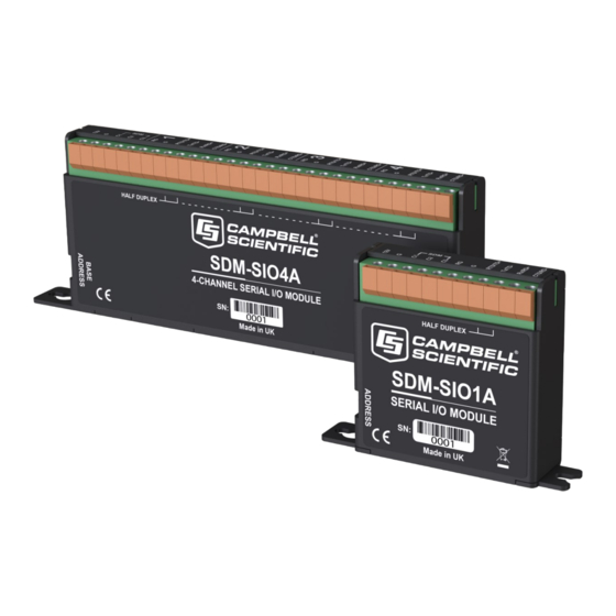
1. Introduction The SDM-SIO1A and SDM-SIO4A Serial Input/Output Modules are designed to allow expansion of the number of serial ports available on a data logger for communicating with intelligent sensors or driving external displays. The SDM-SIO1A is a functional replacement for the SDM-SIO1 interface, being slightly smaller and having different labelling for some terminals (see Matching SDM-SIO1A connections to an SDM-SIO1... -
Page 8: Precautions
Figure 1-2. SDM-SIO1A Serial Input/Output Module For simplicity, except in sections specific to the SDM-SIO4A, only the SDM-SIO1A is referred to in the text of this manual. All of the information in the manual applies to both products unless otherwise noted. 2. -
Page 9: Initial Inspection
Contact Campbell Scientific to facilitate repair or replacement. 4. Overview The SDM-SIO1A expands the number of serial ports on a Campbell Scientific data logger. It can be used as a means of collecting data from digital sensors and/or to send commands to sensors and devices. -
Page 10: Specifications
5. Specifications 5.1 Supported data rates and protocols SerialOpen() Data rates and protocols are set up using the instruction in CRBasic. The SerialOpen() instruction is discussed in SerialOpen() (p. 18). Supported data rates: 300, 1200, 2400, 4800, 9600, 19200, 38400, 57600, and 115200 bits/s Supported modes of operation: RS-232 (full duplex and receive only) -
Page 11: Electrical Parameters
5.2 Electrical parameters 5.2.1 Current consumption Nominal Notes General currents SerialClose() Standby current SDM-SIO1A 110 µA 150 µA Current after Standby current SDM-SIO4A 500 µA 850 µA has been called RS-232 and RS-485 current consumption (per active port) SerialOpen() After Idle current 4.8 mA 6 mA... -
Page 12: Voltage Specifications
5.2.2 Voltage specifications Minimum Nominal Maximum Connection voltage voltage voltage Power supply, +12 V connection 12 V 30 V RS-232 input threshold low 0.8 V – – RS-232 input threshold high – – 2.4 V RS-232 input absolute maximum – ±15 V ±18 V RS-232 input resistance 3 kΩ... -
Page 13: Temperature And Humidity Ranges
5.3 Temperature and humidity ranges Temperature Range Minimum Maximum Notes Standard range –40 ºC +70 ºC Humidity Minimum Maximum Notes Standard range (non-condensing) 5.4 Dimensions and weight 5.4.1 SDM-SIO1A Main body Height: 64 mm (2.51 in) Width: 62.5 mm (2.46 in) Depth: 22 mm (0.86 in) Main body including base... -
Page 14: Data Logger Compatibility
Use the RG terminal on the SDM-SIO1A for RS-485/422 connections. Some serial sensors are supported by the Campbell Scientific Short Cut program. The SDM-SIO1A can be used with those programs simply by selecting the relevant serial port number... -
Page 15: Mounting
COM port number relevant to the SDM-SIO1A. 6.1 Mounting The SDM-SIO1A is normally mounted on the backplate of a Campbell Scientific enclosure using the screws and plastic inserts provided. The SDM-SIO1A is designed to be installed in a dry, non- condensing environment. - Page 16 There can be up to 15 SDM-SIO1As on a single SDM bus. Each SDM-SIO1A will need to be set to a unique address before they are powered. If any other equipment is present on the bus, whether an SDM-SIO1A or other SDM device, the user will have to ensure their addresses are unique. The SDM-SIO4A has a single address switch.
-
Page 17: Connection And Wiring
Table 6-1: SDM address settings SerialOpen() instruction Rotary switch position SDM address COMPort number Address F is not available as it is the broadcast address. Setting this address will result in the SDM-SIO1A having an address of 0 rather than F. 6.2 Connection and wiring Connection to the SDM-SIO1A is achieved via the 11 terminals arranged along the top of the unit. - Page 18 Table 6-3: SDM-SIO1A functional description of the connections Case text Connection to Description RG – RS-485 ground. Connected to G via 100 Ω 1 W resistor. 0V – (same as other G pin) RS-232 RTS. RS-485 half duplex non-inverting. RTS/TD+ RS-485 full duplex outgoing.
-
Page 19: Wiring Examples For Connecting The Sdm-Sio1A
When connecting multiple SDM devices to a data logger, the SDM connections can either be all connected by separate wires back to the data logger terminals or, as is common if the SDM devices are mounted in a row in an enclosure, jumper wires can be used to daisy-chain the same terminals on each interface together (including power and ground) with one set of wires running back to the data logger. -
Page 20: Rs-485/Rs-422 Full-Duplex, One-To-One Connection Example
6.2.1.1 RS-485/RS-422 full-duplex, one-to-one connection example 6.2.1.2 RS-485 full-duplex, multi-drop example SDM-SIO1A and SDM-SIO4A Serial Input/Output Modules... -
Page 21: Rs-485 Half-Duplex Wiring Example
NOTE: As with all RS-485 configurations, the use of termination resistors is optional. They tend not to be required with shorter cable runs and with modern slew-rate-limited driver technology (as used in the SDM-SIO1A). 6.2.1.3 RS-485 half-duplex wiring example This shows how to connect a single device, but RS-485 half-duplex networks are the most common multi-drop configuration. -
Page 22: Rs-232 Wiring Example With Handshaking
6.2.1.4 RS-232 wiring example with handshaking 6.2.1.5 RS-232 basic 3-wire example 6.2.1.6 Connecting a 9-way socket to the SDM-SIO1A for RS-232 devices This configuration may be used if the device is fitted with a standard 9-way D connector as was commonly fitted to computers for their RS-232 port. - Page 23 configured as a DTE or DCE device and whether it has a male or female connector before making up this cable. In RS-232 mode, the main use of the CTS/RD– and RTS/TD+ lines is as RTS/CTS hardware handshaking lines. CTS/RD– should be connected to the remote equipment RTS, and RTS/TD+ to its CTS line.
-
Page 24: Programming
CRBasic to send and receive data using the SDM-SIO1A. Please contact Campbell Scientific for further assistance or training. The Campbell Scientific user forum is also a useful resource to check if others might have already written code for a specific serial device. - Page 25 setting the rate to a negative number sets the automatic flow control system (RTS/CTS). This system is discussed in greater detail in Using RTS/CTS and automatic handshaking 24). SerialOpenFormat This parameter sets the data format. It also determines whether the SDM-SIO1A works in normal RS-232, listen-only RS-232, full-duplex RS-485, or half-duplex RS-485 mode as defined in the following tables.
- Page 26 Table 6-5: Communications port parameters RS-485 full duplex SerialOpenFormat Parity No. stop bits No. data bits None Even None Not used Even None Not used Even None Not used Even None This mode is only supported if there is at least a one-bit delay between characters received by the SDM-SIO1A. SDM-SIO1A and SDM-SIO4A Serial Input/Output Modules...
- Page 27 Table 6-6: Communications port parameters RS-485 half duplex SerialOpenFormat Parity No. stop bits No. data bits None Even None Not used Even None Not used Even None Not used Even None This mode is only supported if there is at least a one-bit delay between characters received by the SDM-SIO1A. SDM-SIO1A and SDM-SIO4A Serial Input/Output Modules...
-
Page 28: Serialclose()
Table 6-7: Communications port parameters RS-232 receive-only mode SerialOpenFormat Parity No. stop bits No. data bits None Even None Not used Even None Not used Even None Not used Even None This mode is only supported if there is at least a one-bit delay between characters received by the SDM-SIO1A. 6.3.1.2 SerialClose() This will place the SDM-SIO1A unit into shutdown mode where only SDM communications will operate. -
Page 29: Serialout()
SDM-SIO1A to the data logger in approximately 2.7 ms. Time (in microseconds) = (10 + 1) × (8 × 30) Note that 30 µs per bit is the default data rate for most Campbell Scientific data loggers. It is SDMSpeed() possible to reduce this time and the transfer time by using the instruction. -
Page 30: Serialinchk()
6.3.1.7 SerialInChk() This returns the number of characters that have been received by the SDM-SIO1A and that are currently held in its buffer (0-6143). 6.3.1.8 SerialInRecord() No special information. 6.3.1.9 SerialFlush() This instruction will purge all information in the data logger and SDM-SIO1A transmit and receive buffers. -
Page 31: Rs-485 Half-Duplex Mode
Enabling handshaking will increase active current consumption due to the extra RS-232 load. It will not affect sleep current, however, as the RS-232 chip is disabled (sleep is set by calling the SerialClose() function). For connection diagrams and further information on using handshaking, consult Wiring examples for connecting the SDM-SIO1A (p. -
Page 32: Power Conservation
7.2 Power conservation The SDM-SIO1A features an industry-standard RS-232/RS-485 driver chipset to ensure maximum likelihood of compatibility with all other devices. When the driver is powered on, it uses more power than one of the data logger control-port-based COM ports — typically 6 mA minimum. This is partly because it generates the correct signal levels, which in itself requires power, and partly because, in the case of RS-232 signals, the resting state of ~ –6 V driving a nominal RS-232 ~3 k load implicitly wastes ~2 mA of current per line. -
Page 33: Troubleshooting And Maintenance
Figure 7-1. RS-485 internal circuit diagram RG is for connecting the screen/ground of the data lines when in RS-485 mode; there is a 1 W 100 Ω resistor in series designed to limit any currents that may be induced due to a difference in ground potentials between the sensor and the SDM-SIO1A. - Page 34 framing, or overrun error is detected. These errors are only flagged for RS-232/RS-485/RS-422 data coming into the SDM-SIO1A. These types of errors are usually caused by a connection issue or sometimes a mismatch of the interface type, baud rate, or data format (parity, etc.). Some confusion can be caused in debugging such problems because it is possible for the communication to partly work even with such mismatches, for instance: Mismatched parity settings will often show many valid characters interspersed with invalid...
-
Page 35: Maintenance
This checksum is stored in memory. This signature value can be read back using the data logger and compared to the signature supplied with the operating system version that was just loaded (contact Campbell Scientific if you need to do this). -
Page 36: Checking The Operating System Version And Signature
9600 bps, 8-bits, 1 stop, and no parity. If this error is seen, contact Campbell Scientific to obtain a copy of the latest operating system and load it into the SDM-SIO1A using the preceding procedure. If this does not correct the fault, the unit may be faulty and will need to be returned to the factory for repair. - Page 37 CRBasic Example 1: Checking the operating system version and signature ' -------------------------------------------------------------------------- ' Simple OS version and OS sig check for the SDM-SIO1A ' -------------------------------------------------------------------------- 'Variables and constants for the version number and signature checking Public Ver_Value As String 25 'Holds version as text string Public Sig_Value As String...
-
Page 38: Appendix A. Using The Handshaking Lines For General Input/Output
Appendix A. Using the handshaking lines for general input/output This appendix describes how to use the CTS and RTS lines for input and output ports. The I/O pins (CTS/pin 11 and RTS/pin 8) can be read or set by the user as required, allowing unique protocols to be created, or they can simply be used as flags or enable lines. -
Page 39: The Output Pin (Rts/Pin 8)
CRBasic Example 2: Detecting the state of the input line 'CR1000 example program showing how to detect the state of the input line on an 'SDM-SIO1A using the SDMGeneric instruction Public sio1response As Long, Inputstate As Boolean Const addr = 0 'constant sdm address CHANGE with SDM-SIO1A address Const cmd =... - Page 40 SerialOutBlock() The following examples show you how to set the output pin using the instruction. CRBasic example for setting the output pin SerialOutBlock(32, 1, 0) 'This will set the spare output pin high SerialOutBlock(32, 0, 0) 'This will set the spare output pin low The preceding two example lines of code will set the output pin on the SDM-SIO1A high then low respectively on the SDM-SIO1A device set to address 0 on its rotary switch.
-
Page 41: Appendix B. Example Data Logger Programs
If you are struggling to write code, please contact Campbell Scientific who may already have experience with the sensor and may be able to offer advice on how to deal with it. -
Page 42: Example Using Rs-232 Mode
B.1 Example using RS-232 mode CRBasic Example 3: RS-232 mode example '----------------------------------------------------------------------- ' Example use of the SDM-SIO1A. ' This example shows how to open a serial port using an SDM-SIO1A. ' A prompt is sent from the data logger to the sensor and it then waits for a ' response before reading the data. -
Page 43: Example Using Rs-485 Mode
B.2 Example using RS-485 mode CRBasic Example 4: RS-485 mode example '----------------------------------------------------------------------- 'Example use of the SDM-SIO1A. 'This example shows how to open the RS-485 serial port using an SDM-SIO1A. 'Data is sent from the data logger to the sensor. 'The program then sits in a loop until the SDM-SIO1A reports it has data 'available 'The data logger then retrieves the data and places it into a string... - Page 44 CRBasic Example 4: RS-485 mode example 'Convert string to float ConvertedValue = ReturnedData 'add an offset to the returned floating point value ConvertedValue = ConvertedValue + 100 SerialClose (SensorPort) 'Close the serial port to the sensor 'this places the SDM-SIO1A into its lowest power mode Next Scan EndProg SDM-SIO1A and SDM-SIO4A Serial Input/Output Modules...
-
Page 45: Appendix C. Matching Sdm-Sio1A Connections To An Sdm-Sio1
Appendix C. Matching SDM-SIO1A connections to an SDM-SIO1 This section is provided for users who are familiar with the older SDM-SIO1, so they can cross reference connections between the new and old devices. The SDM-SIO1A has fewer terminals and different labelling than the SDM-SIO1. It does, however, perform in exactly the same way and can be used as a drop-in substitute with only minor changes to the wiring. - Page 46 Table C-1: Pin cross connection table for SDM-SIO1 to SDM-SIO1A SDM-SIO1 SDM-SIO1A Case text Case text CTS-B CTS/RD– RTS-Y RTS/TD+ TX-Z Tx/TD– Tx/TD– RTS/TD+ CTS/RD– Rx/RD+ SDM-SIO1A and SDM-SIO4A Serial Input/Output Modules...
- Page 47 Campbell Scientific Regional Offices Australia France Thailand Location: Garbutt, QLD Australia Location: Vincennes, France Location: Bangkok, Thailand Phone: 61.7.4401.7700 Phone: 0033.0.1.56.45.15.20 Phone: 66.2.719.3399 Email: info@campbellsci.com.au Email: info@campbellsci.fr Email: info@campbellsci.asia Website: www.campbellsci.com.au Website: www.campbellsci.fr Website: www.campbellsci.asia Brazil Germany Location: São Paulo, SP Brazil...
Need help?
Do you have a question about the SDM-SI01A and is the answer not in the manual?
Questions and answers