Datalogic Matrix 320 Product Reference Manual
Image based industrial reader
Hide thumbs
Also See for Matrix 320:
- Product reference manual (220 pages) ,
- Quick start manual (2 pages)
Table of Contents
Advertisement
Quick Links
Advertisement
Table of Contents

Related Manuals for Datalogic Matrix 320


Summary of Contents for Datalogic Matrix 320
- Page 1 Matrix 320™ PRODUCT REFERENCE GUIDE Image Based Industrial Reader...
- Page 2 Electronic versions of this document may be downloaded from the Datalogic website (www.datalogic.com). If you visit our website and would like to make comments or suggestions about this or other Datalogic pub- lications, please let us know via the "Contact" page.
-
Page 3: Table Of Contents
Laser Safety ........................x LED Safety ........................x HANDLING ........................XI GENERAL VIEW .......................XIII Matrix 320 with 14 LEDs Illuminator ................xiii Matrix 320 with 36 LEDs Illuminator ................xiv RAPID CONFIGURATION....................1 Step 1 - Connect the System .................... 1 CBX100/CBX500 Pinout for Matrix 320 ....................2... - Page 4 ID-NET Connection Diagrams ......................68 Auxiliary RS232 Interface ....................71 Inputs ..........................72 External Trigger Input Connections Using Matrix 320 Power ............73 External Trigger Input Connections Using External Power ............75 Input 2 Connections Using Matrix 320 Power .................76 Input 2 Connections Using External Power ..................77 Input 3 Connections (CBX500 Only) ....................
- Page 5 READING FEATURES ....................91 FOV Calculation ......................91 Global FOV Diagrams ..................... 92 Global FOV for Matrix 320 LQL-9 .....................93 Global FOV for Matrix 320 LQL-16 ....................94 Maximum Line Speed and Exposure Time Calculations ............ 95 SOFTWARE CONFIGURATION ..................97 DL.CODE System Requirements ..................
- Page 6 ALTERNATIVE CONNECTIONS................. 166 Power, Com and I/O Connector for Standard Models ............166 On-Board Ethernet Connector ..................167 ID-NET Network Termination ..................167 Inputs .......................... 168 Outputs ........................168 User Interface - Serial Host ..................170 GLOSSARY......................171 MATRIX 320...
-
Page 7: Preface
TECHNICAL SUPPORT Support Through the Website Datalogic provides several services as well as technical support through its website. Log on to (www.datalogic.com). For quick access, from the home page click on the search icon , and type in the name of the product you’re looking for. -
Page 8: Reseller Technical Support
PREFACE Reseller Technical Support An excellent source for technical assistance and information is an authorized Datalogic reseller. A reseller is acquainted with specific types of businesses, application software, and computer systems and can provide individualized assistance. viii MATRIX 320... -
Page 9: Compliance
Datalogic commercial reference contacts. Since April 20th, 2016 the main European directives applicable to Datalogic products require inclusion of an adequate analysis and assess- ment of the risk(s). This evaluation was carried out in relation to the applicable points of the standards listed in the Declaration of Conformity. -
Page 10: Laser Safety
Le(s) mettre sur le produit à la place de la version anglaise. Exemple d’étiquettes d’avertissement laser LED SAFETY For all Datalogic Matrix 320 compatible internal illuminators, LED emission is classified into Risk Group 1 according to EN 62471:2010. MATRIX 320... -
Page 11: Handling
HANDLING Matrix 320 is designed to be used in an industrial environment and is built to withstand vibration and shock when correctly installed, however it is also a precision product and therefore before and during installation it must be handled correctly to avoid damage. - Page 12 UV illumination. Avoid exposing the product to UV light or direct sunlight. If it is not possible to remove UV light sources, the use of anti-UV receiving filter is mandatory to minimize the probability of damage. CAUTION MATRIX 320...
-
Page 13: General View
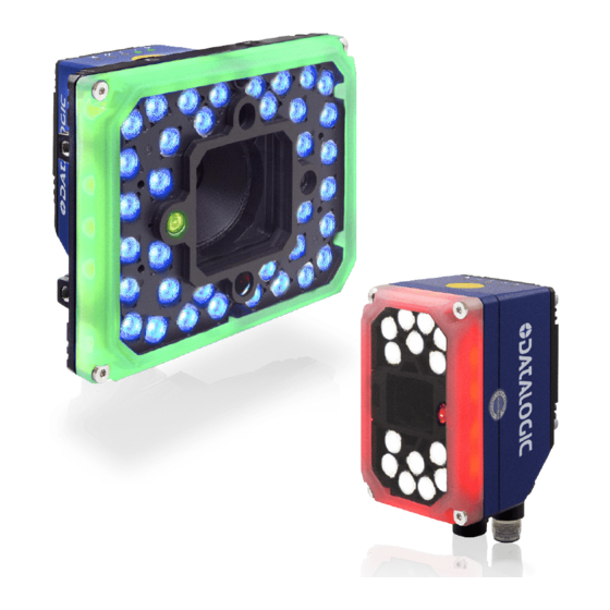
GENERAL VIEW Matrix 320 comes with two different illuminators: with 14 LEDs and with 36 LEDs. MATRIX 320 WITH 14 LEDs ILLUMINATOR Figure 1 - Matrix 320 with 14 LEDs illuminator 1. Lens Cover 9. Bracket Mounting Holes (4) 2. HMI X-PRESS Interface 10. -
Page 14: Matrix 320 With 36 Leds Illuminator
GENERAL VIEW MATRIX 320 WITH 36 LEDs ILLUMINATOR Figure 2 - Matrix 320 with 36 LEDs illuminator 1. HMI X-PRESS Interface 9. Bracket Mounting Holes (4) 2. Lens Cover 10. Ethernet Connector 3. Lens 11. Power - COM - I/O Connector 4. -
Page 15: Rapid Configuration
CAB-ETH-X-M0x CAB-DSxx-S Matrix 320 PG6000 Ethernet Interface Auxiliary Serial Interface (RS232 - Data Monitor) External Trigger (for One Shot or Phase Mode) Figure 3 - Matrix 320 in Stand Alone Layout PRODUCT REFERENCE GUIDE... -
Page 16: Cbx100/Cbx500 Pinout For Matrix 320
RAPID CONFIGURATION CBX100/CBX500 Pinout for Matrix 320 The table below gives the pinout of the CBX100/CBX500 terminal block connectors. Use this pinout when the Matrix 320 reader is connected by means of the CBX100/CBX500: GROUP LABEL DESCRIPTION Power Supply Input Voltage +... -
Page 17: Step 2 - Mount And Position The Reader
STEP 2 - MOUNT AND POSITION THE READER STEP 2 - MOUNT AND POSITION THE READER 1. To mount the Matrix 320, use the mounting brackets to obtain the most suitable position for the reader. The mounting solutions are provided in "... -
Page 18: Step 3 - Aim And Autofocus The Reader
RAPID CONFIGURATION STEP 3 - AIM AND AUTOFOCUS THE READER Matrix 320 provides a built-in laser pointer aiming system to aid reader positioning. For Liquid Lens models, the autofocus feature is also incorporated into this function. The aiming system is accessed through the X-PRESS Interface. -
Page 19: Step 4 - X-Press Configuration
The Setup procedure ends when the Image Acquisition parameters are successfully saved in the reader memory, the Setup LED will stop blinking and Matrix 320 emits 3 high pitched beeps. If the calibration cannot be reached after a timeout of about 5 (five) seconds Matrix 320 will exit without saving the parameters to memory, the Setup LED will stop blinking and in this case Matrix 320 emits a long low pitched beep. -
Page 20: Learn
Green Spot is acti- vated, the Learn LED will stop blinking and Matrix 320 emits 3 high pitched beeps If the autolearning cannot be reached after a timeout of about 3 (three) minutes Matrix 320 will exit without saving the parameters to memory, the Learn LED will stop blinking and in this case Matrix 320 emits a long low pitched beep. -
Page 21: Reset Reader To Factory Default Environment (Optional)
X-PRESS push button pressed while powering up the reader. You must keep the X-PRESS push button pressed until all LEDs blink simultaneously, then release and re-press the button immediately. The Matrix 320 will emit a high pitched beep and after a few seconds enters run mode. -
Page 22: Step 5 - Installing Dl.code Configuration Program
NOTE 2. When the installation is complete the DL.CODE entry is created in the Start>Pro- grams bar under “Datalogic” as well as a desktop icon. Double-click the desktop icon to run it. This configuration procedure assumes a laptop computer, running DL.CODE, is con- nected to a factory default reader through the Ethernet port. -
Page 23: Ethernet Device Discovery
STEP 5 - INSTALLING DL.CODE CONFIGURATION PROGRAM Ethernet Device Discovery To discover models through serial communication instead of Ethernet communication, refer to the DL.CODE User’s Manual (par. “Serial Device Discovery”). NOTE The User Interface opens and displays a list of all the devices belonging to the Local Area Network. - Page 24 Figure 11 - Device Environment Configuration Window 6. Click OK; the device will reappear in the list of Online Devices (in color) meaning it is now part of the LAN and can be configured. The new IP address will also be dis- played. MATRIX 320...
- Page 25 STEP 5 - INSTALLING DL.CODE CONFIGURATION PROGRAM 7. Double-click on or drag the device icon into the Selected Device Information Area. Details about the device will be displayed in this area. Figure 12 - DL.CODE Opening Window PRODUCT REFERENCE GUIDE...
-
Page 26: Step 6 - Device Configuration
If your application requires multiple code symbologies, multiple image settings, Code Grading or other parameter settings for decoding, then use the Advanced Setup, see page 15. NOTE MATRIX 320... -
Page 27: Automatic Setup
STEP 6 - DEVICE CONFIGURATION Automatic Setup To begin configuration, the reader must be correctly mounted so that its Field of View covers the application reading area. 1. From the Task Area select Open Device Configuration. 2. The Open Device Configuration window opens showing the list of currently saved configurations (jobs) saved on the device. - Page 28 7. Click Start to begin the procedure. The reader begins acquiring images. At the end of the procedure the Status: Completed message appears. You can Close the Automatic Setup window. Your reader is now optimized for decoding. Continue with the Reading Phase configura- tion described on page 22. MATRIX 320...
-
Page 29: Advanced Setup For Software Adjustable Focus Models (Liquid Lens)
STEP 6 - DEVICE CONFIGURATION Advanced Setup for Software Adjustable Focus Models (Liquid Lens) To begin configuration, the reader must be correctly mounted at the correct reading dis- tance for your application so that its Field of View covers the application reading area. 1. - Page 30 RAPID CONFIGURATION 5. Click the Image Settings branch and then click the Image Auto-Setup button to automatically acquire the best exposure time and gain values. MATRIX 320...
- Page 31 STEP 6 - DEVICE CONFIGURATION 6. Select the Static or Dynamic Self-Tuning option; Start the Image Auto Setup and Apply to the Image Settings. For applications having multiple lighting or code reading conditions, up to 10 different Image Settings can be configured by adding them with the icon.
- Page 32 7. Now select the General Image Settings branch and click on the Focus Autolearn button. The Reading Distance value is not sig- nificant until the Focus Autolearn pro- cedure ends successfully. 8. The Calibrate dialog box opens allowing you to start the procedure. Click Start. MATRIX 320...
- Page 33 STEP 6 - DEVICE CONFIGURATION At the end of the calibration you can see the new Reading Distance. Click Apply. PRODUCT REFERENCE GUIDE...
- Page 34 10. Click on the Data Matrix ECC 200 symbology under the Image Settings branch (enabled by default). If this symbology is among those in your application it will be shown in the image display with its code symbology name and a small green box around it indicating it is decoded. MATRIX 320...
- Page 35 STEP 6 - DEVICE CONFIGURATION The large green box for each symbol indicates the code localization area which by default is equal to the maximum FoV. It can be resized and moved by dragging its borders with the mouse. The code must be found NOTE within this area in order to be decoded.
-
Page 36: Reading Phase
Parameters tree area: Continuous, One Shot, Phase Mode or PackTrack. 2. Configure the relative Operating Mode parameters from the Reading Phase parameters panel. Different groups will appear in the panel depending on the selected icons over the Configuration Parameters tree area. MATRIX 320... -
Page 37: Good Read Setup
STEP 6 - DEVICE CONFIGURATION Good Read Setup 1. Select your specific data collection type from the icons over the Configuration Parameters tree area: Code Collection, Code Combination, Presentation or Match Code. Not all data collection types are available for all Operating Modes; for exam- ple PackTrack Operating Mode only supports Code Combination. -
Page 38: Data Formatting
Field area. They will be appended to the message. You can drag them to position them between other fields in the message so that the output message is ordered according to your application requirements. Each field has its own relative configuration parameters in the parameters panel. MATRIX 320... -
Page 39: Output Setup
STEP 6 - DEVICE CONFIGURATION Output Setup 1. Configure your application specific Digital Output(s), Green/Red Spots and 360° Feedback (if used) from the Configuration Parameters tree area: Output 1, Output 2, etc. Save the configuration from temporary memory to permanent memory, overwriting the previously saved configuration. -
Page 40: Step 7 - Test Mode
3. To exit the Test, press the X-PRESS push button once. By default, the Test exits automatically after three minutes. NOTE The Bar Graph has the following meaning: In case of No Read condition, only the STATUS LED (red) is on and blinks. MATRIX 320... -
Page 41: Advanced Reader Configuration
ADVANCED READER CONFIGURATION ADVANCED READER CONFIGURATION For further details on advanced product configuration, refer to the DL.CODE User’s Guide available in the DL.CODE Help menu. Host Mode Programming The reader can also be partially configured from a host computer using the Host Mode programming procedure. -
Page 42: Introduction
CHAPTER 2 INTRODUCTION PRODUCT DESCRIPTION Matrix 320 is a Datalogic industrial compact 2D imager designed and produced to be a high performance affordable solution for both linear and two-dimensional code reading applications. Matrix 320 uses imaging technology and provides complete reading system functions by integrating image capturing, decoding and communicating in a single compact and ver- satile product. -
Page 43: Standard Application Program
This technology intrinsically provides omni-directional reading. Standard Application Program A Standard Application Program is factory-loaded onto Matrix 320. This program con- trols code reading, data formatting, serial port and Ethernet interfacing, and many other operating and control parameters. It is completely user configurable from a Lap- top or PC using the dedicated configuration software program DL.CODE, provided on... -
Page 44: Flexible Solution
Sealed circular M12 connectors • IP67 and IP65 protection class • 0 to 45 °C (Liquid Lens models) operating temperature • Supply voltage: 24 Vdc The reader is particularly suitable for industrial environments where protection against harsh external conditions is required. MATRIX 320... - Page 45 PRODUCT DESCRIPTION The reader is contained in an aluminum housing; with its internal illuminator, Liquid Lens and protective cover, the mechanical dimensions are 109 x 54 x 56 mm for the 14 LEDs model and 116 x 126 x 70 mm for the 36 LEDs model. Electrical connection of Power, Serial interfaces and I/O signals is provided through an M12 17-pin connector.
-
Page 46: Indicators And Keypad Button
X-PRESS Human Machine Interface. The keypad button (Figure 14, 8) is software programmable. By default it starts the X- PRESS interface for quick installation without using a PC (see " Step 3 - Aim and Autofocus the reader" on page 4 MATRIX 320... -
Page 47: Green/Red Spot And 360° Visual Feedback
GREEN/RED SPOT AND 360° VISUAL FEEDBACK GREEN/RED SPOT AND 360° VISUAL FEEDBACK Matrix 320 is equipped with a Green/Red Spot and 360° Visual Feedback through col- ored LEDs mounted around the illuminator window cover to provide immediate feed- back on the device status during operation. -
Page 48: Id-Net
Thanks to ID-NET, data communication among readers is highly efficient so that an immediate result will be available. See " for connection details and " ID-NET Interface" on page 66 Internal Network Configura- for configuration details. tions" on page 120 MATRIX 320... - Page 49 ID-NET • ID-NET Multidata: Multiple stations – single reader ID-NET interface allows connection of readers reading objects placed on independent conveyors. All readers are typically located far away from each other and they can have different operating modes from each other. At the end of each reading phase, each reader transmits its own data message to the host.
-
Page 50: X-Press Human Machine Interface
Test with bar graph visualization to check static reading performance • Aim/Autofocus to turn on the aiming system and aid positioning and focusing • Setup to perform Exposure Time and Gain calibration • Learn to self-detect and auto-configure for reading unknown codes MATRIX 320... -
Page 51: X-Press Functions
X-PRESS HUMAN MACHINE INTERFACE X-PRESS Functions Quick access to the following functions is provided by an easy procedure using the push button: 1. Press the button (the Status LED will give a visual feedback). 2. Hold the button until the specific function LED is on (Test, Focus, Setup or Learn). 3. -
Page 52: Aim/Autofocus
If the calibration cannot be reached after a timeout of about 3 (three) minutes, Matrix 320 will exit without saving the parameters to memory, the Learn LED will not remain on continuously but it will stop blinking. In this case Matrix 320 emits a long low pitched beep. -
Page 53: Diagnostic Indication
Status Blink MODEL DESCRIPTION Matrix 320 readers are described by their model number which indicates the character- istics listed in the diagram below. Not all combinations are available. For a complete list of combinations see " Available Models" on page 40... -
Page 54: Available Models
Matrix 320 725-430 L16 36L 25D RED 938100033 Matrix 320 726-430 L16 36L 25D WHT 938100034 Matrix 320 727-430 L16 36L 25D BLU ACCESSORIES The following accessories can be used with the Matrix 320 reader. Accessory Description Order No. Cables CAB-DS01-S... - Page 55 ACCESSORIES Accessory Description Order No. CAB-F-ETH-X-M01 M12-IP67 GIGA Ethernet Flexible Cable X-Coded (1M) 93A050125 CAB-F-ETH-X-M03 M12-IP67 GIGA Ethernet Flexible Cable X-Coded (3M) 93A050126 CAB-F-ETH-X-M05 M12-IP67 GIGA Ethernet Flexible Cable X-Coded (5M) 93A050127 CAB-ETH-X-RJ Adapter Cable Full GETH-X to RJ45 93A050141 CBL-1480-01 Thin M12/5P Male/Female (1M) 93A050049...
-
Page 56: Application Examples
93ACC0116 APPLICATION EXAMPLES Document Handling Matrix 320 is profitably used in the omnidirectional reading of 2D, stacked, linear and postal codes for example in automated document handling and mail processing sys- tems. Figure 16 - Address Coded in Data Matrix Symbology for Automated Mail Processing... -
Page 57: Multiple Reading In A Single Image
APPLICATION EXAMPLES Multiple Reading in a Single Image The Matrix 320 high resolution image sensors allow the reading of many small codes in a single image. Figure 17 - 96-Vial Rack Deformed or Overprinted Code Reading Matrix 320 assures the reading of deformed and/or overprinted codes, even though damaged or printed on high reflective surfaces. -
Page 58: Direct Part Marking
INTRODUCTION Direct Part Marking Matrix 320 is also very powerful in reading low-contrast direct part marked codes. Figure 21 - Dot Matrix Code Directly Marked on Metal Surface by Using Dot Peening Technology Figure 22 - Dot Peening Marking on Metal Surface with Multi-dot per Code Element... -
Page 59: Laser Marking/Etching Technology
Technology If application codes must be read which are produced by Laser Marking in real time, use the correct diameter accessory YAG Cut Filter with the Matrix 320 reader in order to avoid burning the sensor. CAUTION PRODUCT REFERENCE GUIDE... -
Page 60: High Dynamic Range (Hdr) Feature
INTRODUCTION High Dynamic Range (HDR) feature Matrix 320 supports the High Dynamic Range (HDR) feature. HDR performs an image dynamic correction where low intensity pixel values are enhanced, thus improving image contrast and code readability. This feature proves particularly useful in the following cases: •... - Page 61 APPLICATION EXAMPLES • To improve decodability when the FoV includes codes with different levels of con- trast: HDR disabled HDR enabled In the example above, when HDR is disabled only two out of four codes are decoded. After enabling HDR, all four codes are decoded. •...
- Page 62 For more details on line speed and exposure time calculations, refer to " Maximum Line Speed and Exposure Time Calculations" on page 95 To enable the HDR function on DL.CODE, go to Advanced Setup>Image Settings>Image Quality>HDR Selector, then select HDR. Figure 26 - Enabling HDR on DL.CODE MATRIX 320...
-
Page 63: Installation
CHAPTER 3 INSTALLATION PACKAGE CONTENTS Verify that the Matrix 320 reader and all the parts supplied with the equipment are present and intact when opening the packaging; the list of parts includes: • Matrix 320 reader • Matrix 320 Quick Reference Guide •... -
Page 64: Mechanical Dimensions
INSTALLATION MECHANICAL DIMENSIONS Matrix 320 can be installed to operate in different positions. The four screw holes (M4 x 8 mm) on the body of the reader are for mechanical fixture. The diagrams below give the overall dimensions of the reader and may be used for its installation. - Page 65 MECHANICAL DIMENSIONS [inch] Figure 29 - Overall Dimensions: Matrix 320 with 36 LEDs illuminator (connectors 0°) [inch] Figure 30 - Overall Dimensions: Matrix 320 with 36 LEDs illuminator (connectors 90°) PRODUCT REFERENCE GUIDE...
- Page 66 INSTALLATION [inch] Figure 31 - Overall Dimensions: BK-32-000 Standard Fix Bracket for Matrix 320 with 14 LEDs illuminator MATRIX 320...
- Page 67 MECHANICAL DIMENSIONS [inch] Figure 32 - Overall Dimensions: BK-32-00 Pivot Fix Bracket (1) for Matrix 320 with 36 LEDs illuminator [inch] Figure 33 - Overall Dimensions: BK-32-00 Pivot Fix Bracket (2) for Matrix 320 with 36 LEDs illuminator PRODUCT REFERENCE GUIDE...
-
Page 68: Mounting And Positioning Matrix 320
INSTALLATION MOUNTING AND POSITIONING MATRIX 320 The following accessory mounting brackets are available for mounting and positioning Matrix 320: Figure 34 - BK-32-000 Standard Fix Bracket Figure 35 - BK-32-010 Pivot Fix Bracket MATRIX 320... -
Page 69: Mounting The Bk-32-00 Standard Fix Bracket
MOUNTING AND POSITIONING MATRIX 320 Mounting the BK-32-00 Standard Fix Bracket The package contains the following materials to mount the Standard Fix Bracket: • 1 Standard Fix Bracket • 3 silver screws • 3 silver washers Make sure that the heat sink is already installed on the reader before mounting the bracket (refer to the Heat Sink Mounting Instructions pro- vided in the package). -
Page 70: Mounting The Bk-32-010 Pivot Fix Bracket
SET 2 with standard holes, used for Extended Mounting Figure 37 - Pivot Fix Bracket (body side) Compact Mounting Compact mounting allows installations with minimal side space and reader optical axis aligned with the bracket central hole. Figure 38 - Compact mounting MATRIX 320... -
Page 71: Extended Mounting
MOUNTING AND POSITIONING MATRIX 320 Extended Mounting Extended mounting allows: • side installations with wider range of tilt angles than compact mounting (because the side bracket frame is outside the reader volume): Figure 39 - Extended mounting • frontal installations:... - Page 72 3. Tighten two silver screws and two silver washers into the aligned holes to secure the position. Finally tighten the central screw. The particular distribution of the holes on the two brackets allows easy adjustment of the skew angle in steps of 15°. NOTE Figure 41 - Skew angle adjustment MATRIX 320...
- Page 73 In some cases, such as low contrast or low illumination, it can be useful to use a Pitch or Skew angle = 0°. The Tilt angle is also represented in Figure 42. Matrix 320 can read labels with any tilt angle. Keep in mind however, that since linear barcodes are rectangular, the reader should be aligned to fit them into the horizontal FOV.
-
Page 74: Cbx Electrical Connections
CAB-DSxx-S accessory cables. These accessory cables terminate in a 17-pin connector on the Matrix 320 side and in a 25-pin male D-sub connector on the CBX side. We recommend making system connections through one of the CBX connection boxes since they offer the advantages of easy connection, easy device replacement, opto-iso- lated output signals, and filtered reference signals. -
Page 75: Cbx Connection Box Pinout
CBX CONNECTION BOX PINOUT CBX CONNECTION BOX PINOUT The table below gives the pinout of the CBX100/500 terminal block connectors. Use this pinout when the Matrix 320 reader is connected by means of the CBX100/500: Group Label Description Input Power Supply Input Voltage +... -
Page 76: Cab-Ds0X-S Pinout
CBX ELECTRICAL CONNECTIONS CAB-DS0x-S PINOUT 17 PINS NAME 25 PINS 9-13 7-25 XTRG_A XTRG_B IN2A IN2B OUT3 14-16 OUT2 OUT1 CO/TX C2/RX C1/RTS C3/CTS NET+ NET- SHIELD 12, 15, 17, 22 Not connected MATRIX 320... -
Page 77: Power Supply
POWER SUPPLY POWER SUPPLY Power can be supplied to the reader through the CBX100/500 spring clamp terminal pins as shown in Figure 43: Figure 43 - Power Supply Connections The power must be between 10 and 30 Vdc only. It is recommended to connect the device CHASSIS to earth ground (Earth) by setting the appropriate jumper in the CBX connection box. -
Page 78: Main Serial Interface
The following pins are used for RS232 interface connection: CBX100/500 Description Transmit Data Receive Data SGND Signal Ground It is always advisable to use shielded cables. The overall maximum cable length must be less than 15 m (49.2 ft). Figure 44 - RS232 Main Interface Connections MATRIX 320... -
Page 79: Rs422 Full Duplex Interface
MAIN SERIAL INTERFACE RS422 Full Duplex Interface The RS422 full-duplex (5 wires + shield) interface is used for non-polled communication protocols in point-to-point connections over longer distances (max 1200 m / 3940 ft) than those acceptable for RS232 communications or in electrically noisy environments. The CBX pinout follows: CBX100/500 Description... -
Page 80: Id-Net Interface
250 kbps 500 kbps 1 Mbps Cable Length 1200 m 900 m 700 m * Application dependent, contact your Datalogic representative for details. The default ID-NET baudrate is 500 kbps. Lower ID-NET baudrates allow longer cable lengths. NOTE MATRIX 320... -
Page 81: Id-Net Response Time
ID-NET INTERFACE ID-NET Response Time The following figure shows the response time of the ID-NET network. This time is defined as the period between the Trigger activation and the beginning of data trans- mission to the Host. Figure 47 - ID-NET Response Time Conditions •... -
Page 82: Id-Net Network Termination
The network must be properly terminated in the first and last reader of the network. This is done by setting the ID-NET Termination Resistance Switch in the CBX100/500 to ID-NET Connection Diagrams Figure 48 - ID-NET Network Connections with isolated power blocks MATRIX 320... - Page 83 ID-NET INTERFACE Figure 49 - ID-NET Network Connections with Common Power Branch Network PRODUCT REFERENCE GUIDE...
- Page 84 CBX ELECTRICAL CONNECTIONS Figure 50 - ID-NET Network Connections with Common Power Star Network MATRIX 320...
-
Page 85: Auxiliary Rs232 Interface
AUXILIARY RS232 INTERFACE AUXILIARY RS232 INTERFACE The RS232 auxiliary interface is available for Point-to-Point connections. When it is con- nected to the host computer it allows transmission of code data. The parameters relative to the aux interface (baud rate, data bits, etc.) can be defined through the Reading Phase step (Channels) in DL.CODE. -
Page 86: Inputs
CBX100/500 Description Power Source - External Trigger External Trigger A (polarity insensitive) External Trigger B (polarity insensitive) Power Reference - External Trigger The yellow Trigger LED is on when the active state of the External Trigger corresponds to MATRIX 320... -
Page 87: External Trigger Input Connections Using Matrix 320 Power
Device on the +V/-V spring clamps, and does not pass through the Power Switch (ON/OFF) inside the CBX. Disconnect the power supply when CAUTION working inside the CBX. Figure 53 - PNP External Trigger Using Matrix 320 Power PRODUCT REFERENCE GUIDE... - Page 88 CBX ELECTRICAL CONNECTIONS Figure 54 - NPN External Trigger Using Matrix 320 Power MATRIX 320...
-
Page 89: External Trigger Input Connections Using External Power
INPUTS External Trigger Input Connections Using External Power Figure 55 - PNP External Trigger Using External Power Figure 56 - NPN External Trigger Using External Power CBX100/500 Description Power Source - External Trigger Input 2 A (polarity insensitive) Input 2 B (polarity insensitive) Power Reference - External Trigger PRODUCT REFERENCE GUIDE... -
Page 90: Input 2 Connections Using Matrix 320 Power
Device on the +V/-V spring clamps, and does not pass through the Power Switch (ON/OFF) inside the CBX. Disconnect the power supply when CAUTION working inside the CBX. Figure 57 - PNP Input 2 Using Matrix 320 Power Figure 58 - NPN Input 2 Using Matrix 320 Power MATRIX 320... -
Page 91: Input 2 Connections Using External Power
INPUTS Input 2 Connections Using External Power Figure 59 - PNP Input 2 Using External Power Figure 60 - NPN Input 2 Using External Power Input 3 Connections (CBX500 Only) Figure 61 - Input 3 Using External Power Do not connect to I3A or I34B signals, they are reserved. CAUTION PRODUCT REFERENCE GUIDE... -
Page 92: Outputs
Good Read event, which activates when all the selected codes are correctly decoded. The output signals are fully programmable being determined by the configured Activa- tion/Deactivation events, Deactivation Timeout or a combination of the two. Refer to the DL.CODE parameters Help On Line for further details. MATRIX 320... -
Page 93: Output 1 And 2 Connections Using Matrix 320 Power
Device on the +V/-V spring clamps, and does not pass through the Power Switch (ON/OFF) inside the CBX. Disconnect the power supply CAUTION when working inside the CBX. Figure 62 - PNP/Open Emitter Output Using Matrix 320 Power Figure 63 - NPN/Open Collector Output Using Matrix 320 Power PRODUCT REFERENCE GUIDE... -
Page 94: Output 1 And 2 Connections Using External Power
Output 3 is not opto-isolated but can be assigned to the same events. By default it is not assigned to any event. The CBX500 must be used to connect this output. For Output 3, set the Line Type configuration parameter according to the hardware connection to the CBX: NPN, PNP or Push-Pull. NOTE MATRIX 320... -
Page 95: Output 3 Connections Using Matrix 320 Power (Cbx500 Only)
OUTPUTS Output 3 Connections Using Matrix 320 Power (CBX500 Only) Figure 66 - Output 3 Using Matrix 320 Power Output 3 Connections Using External Power (CBX500 Only) Figure 67 - Output 3 Using External Power Do not connect to I3A or I34B signals, they are reserved. -
Page 96: On-Board Ethernet Interface
The on-board Ethernet Interface can be used for TCP/IP communication with a remote or local host computer by connecting the reader to either a LAN or directly to a host PC. There is no need to use a crossover adapter since Matrix 320 incorporates an auto-cross function. -
Page 97: Typical Layouts
CHAPTER 5 TYPICAL LAYOUTS The following typical layouts refer to system hardware configurations. However, they also require the correct setup of the software configuration parameters. Dotted lines in the figures refer to optional hardware configurations within the particular layout. All software configurations are made through DL.CODE which connects to the reader through the on-board Ethernet interface. -
Page 98: Ethernet Connection
The Ethernet connection is possible in two different layouts. In a Point-to-Point layout the reader is connected to a local host by using a CAB-ETH-X- M0x cable. There is no need to use a crossover adapter since Matrix 320 incorporates an autocross function. - Page 99 ETHERNET CONNECTION When using a Local Area Network (LAN), one or more Matrix 320 readers can be con- nected to the network by using CAB-ETH-X-M0x cables: Alone Alone Alone Matrix 320 Power Host Switch Ethernet Interface Auxiliary Serial Interface (RS232 - Data Monitor) ...
-
Page 100: Serial Connection
When One Shot or Phase Mode operating mode is used, the reader can be activated by an External Trigger (for example a pulse from a photoelectric sensor) when the object enters its reading zone. PG6000 Host CAB-DSxx-S Matrix 320 Alone Terminal Main Serial Interface (RS232 or RS422 Full-Duplex) ... -
Page 101: Fieldbus Connection
When One Shot or Phase Mode operating mode is used, the reader can be activated by an External Trigger (photoelectric sensor) when the object enters its reading zone. Power CAB-DSxx-S CBX500 Matrix 320 Alone Fieldbus Interface (Profibus, DeviceNet, etc.) ... -
Page 102: Pass-Through
Host (i.e. left reader above). All devices always support multiple output channels (i.e. for data monitoring). In a Pass-through layout each device can have a different operating mode: Continuous, One Shot, Phase Mode, etc. MATRIX 320... -
Page 103: Id-Net Multidata Network (Pass-Through)
ID-NET MULTIDATA NETWORK (PASS-THROUGH) ID-NET MULTIDATA NETWORK (PASS-THROUGH) A special case of the pass-through layout allows each Slave device working Alone, to collect data from one or more pass-through input channels and send this data plus its own on the ID-NET output channel to the Master. The Slave readers are connected together using the ID-NET interface. -
Page 104: Id-Net Synchronized Network
The Master reader can be connected to the CBX series connection box with the advan- tage of the Backup and Restore configuration function (CBX + BM100 module). All devices always support multiple output channels (i.e. for data monitoring) MATRIX 320... -
Page 105: Reading Features
Max Focus Model Angle Angle Angle Distance Distance Offset Horizontal Vertical Diagonal (mm) (mm) (mm) Matrix 320 14L 6.1* 34° 19° 39° 1000 LQL 9 mm Matrix 320 14L 20° 11° 23° 1500 LQL 16 mm Matrix 320 36L 6.1* 34°... -
Page 106: Global Fov Diagrams
Figure 75 - Reading Distance References Example: The FOV for a Matrix 320 7xx-330 at a reading distance of 600 mm is: = 2 [(600 mm + 22 mm) * tan (34°/2)] 380 mm = 2 [(600 mm + 22 mm) * tan (19°/2)] 208 mm GLOBAL FOV DIAGRAMS The following diagrams are given for typical performance at 25°C using... -
Page 107: Global Fov For Matrix 320 Lql-9
GLOBAL FOV DIAGRAMS Global FOV for Matrix 320 LQL-9 Codes Reading Distance 2D Codes Reading Distance PRODUCT REFERENCE GUIDE... -
Page 108: Global Fov For Matrix 320 Lql-16
READING FEATURES Global FOV for Matrix 320 LQL-16 1D Codes Reading Distance 2D Codes Reading Distance MATRIX 320... -
Page 109: Maximum Line Speed And Exposure Time Calculations
(internal lighting system, optical lens, reading distance) and on any external lighting system. It may also depend on code printing quality, and reader position. Example A Matrix 320 using: Internal Lighting Mode = Very High Power Strobe ... - Page 110 Therefore, after changes to Internal Lighting, recheck Expo- NOTE sure Time. • Continuous High-Power: the internal lighting system is turned on continuously at the highest power level. This option is useful if the LED-array blinking (Strobed lighting mode) disturbs the operator. MATRIX 320...
-
Page 111: Software Configuration
CHAPTER 7 SOFTWARE CONFIGURATION Software configuration of your Matrix 320 for static reading or simple code reading applications can be accomplished by the Rapid Configuration procedure using the X-PRESS HMI (which requires no external configuration program). This procedure is described in Steps 4-6. -
Page 112: Reader Configuration
Backup to File and/or to an External storage device (BM100, etc.). See " Backup and Restore Through DL.CODE" on page 135 Matrix 320 can contain several configurations or jobs in permanent memory. This means that in addition to your application configuration(s), the... -
Page 113: Auto-Calibration
READER CONFIGURATION Auto-Calibration DL.CODE provides the Image Auto-Setup tool to maximize the reading performance by tuning the acquisition parameters (photometry) automatically. By selecting the Image Auto-Setup tool from the Image Settings branch in the Advanced Setup step, the follow- ing window appears:Select the Static or Dynamic Self-Tuning option; Start Image Auto- Setup and Apply to the Image Settings. -
Page 114: Manual Calibration
Internal Lighting mode parameter. Longer exposure times NOTE can be set if the power strobe level is lowered. High gain settings may produce a grainy image that may affect the decoding process. Figure 77 - Example Under Exposure: Too Dark MATRIX 320... -
Page 115: Over-Exposure
READER CONFIGURATION Over-exposure To correct this result it is recommended to change the following parameters in their order of appearance: 1. decrease the Gain 2. decrease the Exposure Time Figure 78 - Example Over Exposure: Too Light PRODUCT REFERENCE GUIDE... -
Page 116: Moving Code Out Of The Field Of View
• reposition the reader • use the Delay on Trigger and set the Time or Space values. Figure 79 - Example Out of FOV Figure 80 - Add Delay on Trigger to Correct Out of FOV MATRIX 320... -
Page 117: Multi Image Acquisition Settings
MULTI IMAGE ACQUISITION SETTINGS MULTI IMAGE ACQUISITION SETTINGS When controlled variable conditions occur in the application, Multiple Image Acquisi- tion Settings can be defined to create a database of parameter groups that handle each specific application condition. This database of pre-defined settings improves system flexibility and readiness by being applied either automatically or selectively by an activa- tion event. -
Page 118: Automatic Image Settings Selection
Last Successful value, we will start with the Image Setting that last produced a Good Read. For this group of items the last Image Setting used will be correct for the next item and so we start each cycle with the acquisition that will potentially produce a Good Read. MATRIX 320... -
Page 119: External Image Settings Selection
MULTI IMAGE ACQUISITION SETTINGS External Image Settings Selection There are some applications where the lighting conditions are known before each item is read and therefore we can pre-select the correct Image Setting from an external source. When the Image Settings Selection is External, Acquisition Sequences are created and by default each Image Setting has its own Acquisition Sequence. - Page 120 In this case the Start Acquisition From parameter can improve the read rate for that Sequence. It has no meaning for a Sequence containing only one Image Setting. MATRIX 320...
-
Page 121: Extending Dof With Automatic Image Settings Selection (Cycle All In Same Phase) For Liquid Lens Models
EXTENDING DOF WITH AUTOMATIC IMAGE SETTINGS SELECTION (CYCLE ALL IN SAME PHASE) FOR LIQUID LENS MODELS EXTENDING DOF WITH AUTOMATIC IMAGE SETTINGS SELECTION (CYCLE ALL IN SAME PHASE) FOR LIQUID LENS MODELS For Liquid Lens models, multiple Image Acquisition Settings can be configured and enabled internally through the application software to extend the reader's depth of field. -
Page 122: Extending Dof With Automatic Image Settings Selection Sequence (Input Select) For Liquid Lens Models
Sequence with Image Settings #2 is selected with the Image Acquisition Setting relative to the 300 mm Reading Distance. The settings overlap in the range 210-220 mm and can be read by either one. In this way the effective reading DOF covers the 140 -320 mm distance. MATRIX 320... - Page 123 EXTENDING DOF WITH AUTOMATIC IMAGE SETTINGS SELECTION SEQUENCE (INPUT SELECT) FOR LIQUID LENS MODELS Ext. Trigger Proximity Sensor on Input 2 Figure 81 - Example Extending DOF Using External Image Settings Selection Since many factors and parameters contribute to maximizing the reading process, it is suggested to use the DL.CODE Image Auto-Setup and Focus Autolearn tools to set the different acquisitions settings.
-
Page 124: Image Cropping
Setup tab by clicking on the Add Cropping Region icon as shown below. In Matrix 320 the frame rate is dependent on the number of rows and columns in the defined window. Image cropping allows reducing the Image processing area from the full FoV to a smaller area where codes are present. - Page 125 IMAGE CROPPING By dragging the edges with the mouse (resizing) you can crop the image to a specific location where codes are present. The numbers in the blue boxes refer to pixel refer- ences. x,y coordinates of upper left corner of Cropping Region number of pixels in vertical Cropping...
- Page 126 SOFTWARE CONFIGURATION You can also set the cropped image size and position through the Cropping Region Area group of parameters; size = Width and Height, position = Left, Top (x,y) coordinates. MATRIX 320...
-
Page 127: Direct Part Marking Applications
DIRECT PART MARKING APPLICATIONS DIRECT PART MARKING APPLICATIONS For Data Matrix family codes the Decoding Complexity parameter is available when Processing Mode is set to Standard and selects the decoding algorithm according to the printing/marking technique used to create the symbol and on the overall printing/ marking quality. -
Page 128: Image Filter
The Dilate Filter enlarges the image white zones to increase readability. Before - No Read After - Readable The Close filter eliminates dark areas (defects) in the white zones of the image. Before - No Read After - Readable MATRIX 320... - Page 129 DIRECT PART MARKING APPLICATIONS The Open filter eliminates white areas (defects) in the dark zones of the image. Before - No Read After - Readable The Contrast Stretching filter maximizes image contrast. Before - No Read After - Readable PRODUCT REFERENCE GUIDE...
- Page 130 After - Readable The Smoothing filter deletes small (insignificant) details in the center of the image. Before - No Read After - Readable The Sharpening filter improves out of focus images. Before - No Read After - Readable MATRIX 320...
- Page 131 DIRECT PART MARKING APPLICATIONS The Deblurring filter improves blurred images. Before - No Read After - Readable The Black Enhancement filter produces a nonlinear increase in the black level for light images. Before - No Read After - Readable PRODUCT REFERENCE GUIDE...
-
Page 132: Pass-Through Configurations
(also working Alone), and pass this data to a third device through a different communication channel. The following screenshots show the pass-through configuration settings for the three devices in the example in " Pass-Through" on page 88 Reader #1 MATRIX 320... - Page 133 PASS-THROUGH CONFIGURATIONS Reader #2 Reader #3 PRODUCT REFERENCE GUIDE...
-
Page 134: Internal Network Configurations
Mechanical Dimensions" on page 50 and " ) and electrically (refer to " Mounting And Positioning Matrix 320" on page 54 ) with factory default settings (Layout Type = Alone, Inter- NET Interface" on page 66 nal Network Role = Slave). -
Page 135: Master Configuration
INTERNAL NETWORK CONFIGURATIONS Master Configuration First start with the desired device to assign as ID-NET Master (current default setting is Slave). Click on Setup Internal Network Configuration from the Task area. You will be advised that the device role will be changed to Master. Click OK. - Page 136 Depending on the application, select one of the Default Internal Network Configura- tions: Multidata, Synchronized Phase Mode or Synchronized PackTrack. Multidata Synchronized This selection will open a pre-configured job for the Master reader according to the selection. Follow the specific application instructions in the following paragraphs. MATRIX 320...
-
Page 137: Multidata Id-Net Network Configurations
INTERNAL NETWORK CONFIGURATIONS Multidata ID-NET Network Configurations The Multidata ID-NET network communications between Master and Slave are man- aged by the application job (configuration) using the pass-through feature. A pre-config- ured job is loaded with the correct pass-through settings for both the Master and Slaves when the Default Multidata Configuration is selected from the Internal Network Setting feature. - Page 138 SOFTWARE CONFIGURATION Open the Slave specific application job, (it will either have the new name saved from the Master or Temp depending on the Save on Slave Device selection). MATRIX 320...
- Page 139 INTERNAL NETWORK CONFIGURATIONS When the configuration opens, pause run mode and set all the application specific con- figuration parameters (including Image Settings). Verify the focus and decoding with the capture image button. PRODUCT REFERENCE GUIDE...
- Page 140 (but with all Slave specific configuration parameters), has been saved to the Slaves. No parameters have been cloned from the Master. There are no common param- eters managed by the Master for Multidata configurations. MATRIX 320...
- Page 141 INTERNAL NETWORK CONFIGURATIONS PRODUCT REFERENCE GUIDE...
-
Page 142: Synchronized Id-Net Network Configurations
DL.CODE. This is preferably done through each device’s Ethernet TCP/IP channel. If Slave devices are not NOTE connected to Ethernet you must temporarily (manually) connect them one by one to perform Image Settings. MATRIX 320... - Page 143 INTERNAL NETWORK CONFIGURATIONS Open the cloned application job. PRODUCT REFERENCE GUIDE...
- Page 144 (Reading Phase step) • Images Saving if used (Data Formatting step) • Encoder Sensor: if used, (for all Slaves, the Encoder Type must be set to Internal) Verify the focus and decoding with the capture image button. MATRIX 320...
- Page 145 INTERNAL NETWORK CONFIGURATIONS 3. Now save them, overwriting the cloned application job Figure 86 - Saving Synchronized Phase Mode Configuration to Slave Repeat this procedure for each Slave device until the entire network is configured. See " for an example. ID-NET Synchronized Network"...
-
Page 146: Verify Master/Slave Synchronized Configuration
1. Connect to the Master device via Ethernet and from the Data Formatting step, change each Expected Code Field Type from Code Content to Reading Mask. 2. Run the application and monitor the output data from the DL.CODE Console or a configured channel terminal. MATRIX 320... - Page 147 INTERNAL NETWORK CONFIGURATIONS The Reading Mask shows which device reads which Expected Code. The mask is com- posed of a fixed 32-character string (0=No Read or 1=Read) representing the 32 possible readers in an ID-NET network. By default the Master is the last character in the string (Master on Right) but this can be changed.
- Page 148 To save changed slave parameters here, you must click on the Master NOTE and Save the configuration overwriting it, making sure to select Save on Slave Device but without Clone Master Configuration on Slaves, other- wise all the Slave configuration parameters will be overwritten by the Master configuration. MATRIX 320...
-
Page 149: Backup And Restore Through Dl.code
BACKUP AND RESTORE THROUGH DL.CODE BACKUP AND RESTORE THROUGH DL.CODE DL.CODE allows Backup and Restore to be performed to/from the configuration PC via file or to an external storage device such as BM100/BM150. DL.CODE provides complete backup and restore functions (Configuration and Environ- mental parameters) with the following difference: For Single Readers or individual ID-NET Slaves: •... -
Page 150: Backup
Backup. If you are performing a backup to a file you will be asked whether to include the firm- ware or not. At the end of the backup, DL.CODE shows a message indicating successful completion. MATRIX 320... -
Page 151: Restore
BACKUP AND RESTORE THROUGH DL.CODE Restore To perform a Restore: 1. From the DL.CODE Device menu, select either Single Reader Restore (from file on PC); or Restore from external storage device. For ID-NET network Restore, select the Internal Network replacement selection. -
Page 152: Restore Defaults
IP Address = 192.168.3.100 Go to the Device menu >Backup/Restore > Restore Defaults > Restore Default Startup Configuration. Any previously saved configurations on the device will remain in memory, but the Default configuration is set as the startup configuration. MATRIX 320... -
Page 153: Restore Default Startup Configuration
RESTORE DEFAULTS Restore Default Startup Configuration The Default configuration is always present on the reader and in fact it is not modifiable and cannot be deleted. It can always be restored by simply selecting it from the Open from Device configuration list. The same action can be performed from the Device menu >Backup/Restore >... -
Page 154: Diagnostic Alarms
DIAGNOSTIC ALARMS By using the DL.CODE Monitor functions from the File menu (or Monitor icon), you can get information about diagnostic alarms. Any alarms will show up as warning lights on the alarm panel. Figure 87 - Diagnostic Alarms MATRIX 320... -
Page 155: Statistics
STATISTICS STATISTICS Statistics on the reading performance can be viewed by enabling the Statistics panel from the DL.CODE Monitor item selected from the File menu (or Monitor icon). Figure 88 - Reading Statistics The enabled Statistical Counters can be selected from the Device>Settings>Configura- tion Settings menu. -
Page 156: Bm150 Display Module Configuration And Messages
BM150 display module (if present), will also not be enabled. • BM150 Display Layout (Master Only) Reading Mask Only: the Reading Mask screen is sent to the BM150 display. Reading Mask/Device State: the Reading Mask/Device State screen is sent to the BM150 display. MATRIX 320... -
Page 157: Accessing The Hmi Interface Through Keypad And Display Menu
BM150 DISPLAY MODULE CONFIGURATION AND MESSAGES Accessing the HMI Interface Through Keypad and Display Menu Through its keypad and display, the BM150 provides a remote extension of the reader's HMI Interface. The HMI default menu items can be accessed as well as the View menu for Master devices and the Extended menu for Backup and Restore functions. - Page 158 When the reader is connected to DL.CODE, access to the BM150 HMI Interface is disabled. NOTE The "Reset Reader to Factory Default Environment" function of the HMI Interface is only available on the local device (reader), and not on the BM150. NOTE MATRIX 320...
-
Page 159: Display Messages
BM150 DISPLAY MODULE CONFIGURATION AND MESSAGES Display Messages The following examples of Remote Display messages are given to help interpret the information reported. The content of these messages depends on the connected reader. Welcome Message M = scanner model K = software – STD=Standard, SS =Special V = software version R = Device Network Type –... - Page 160 Network State (Master only) M = Master diagnostic condition; S = Slave diagnostic condition: * = scanner OK - =scanner not detected at startup ? =scanner detected at startup but not responding to diagnostic polling ! = scanner diagnostic error MATRIX 320...
- Page 161 BM150 DISPLAY MODULE CONFIGURATION AND MESSAGES Standard Reading Results A = reading result – Good Read, Partial Read, Multiple Read X = code content Y = number of codes read Reading Mask Only (Master Only) X = code content (or "No Read" or "Multiple Read") Y = Good Read, No Read, Multiple Read and Partial Read counters on the last 100 codes read (%) S = Reading Mask for Stand Alone or Master plus Slave readers 1 - 15...
-
Page 162: Bm150 Backup And Restore Procedure
1. Select the Restore item from the Extended menu and press the Enter key. 2. When the procedure is complete a message appears on the display showing the results (Restore OK 1 File Restored or an error message). MATRIX 320... -
Page 163: Illuminators
CHAPTER 8 ILLUMINATORS STANDARD ILLUMINATORS 14 LEDs Illuminator 14 LEDs MODELS AND LED CHAIN CONFIGURATION LIGHTS ON LEDs COLOR All Chains White, Red, Blue Central Chain White, Red, Blue Top/Bottom Chain White, Red, Blue Figure 90 - LED chains for 14 LEDs models PRODUCT REFERENCE GUIDE... -
Page 164: Leds Illuminator
White, Red, Blue Top Left White, Red, Blue Top Right White, Red, Blue Left White, Red, Blue Right White, Red, Blue Bottom Left White, Red, Blue Bottom Right White, Red, Blue Figure 91 - LED chains for 36 LEDs models MATRIX 320... -
Page 165: Polarizer
POLARIZER Figure 92 - Standard and polarizing cover for 14 (left) and 36 (right) LEDs models Matrix 320 also comes with a polarizing cover. This is the ideal solution to reduce hot spots on reflective surface applications, such as: •... - Page 166 ILLUMINATORS DPM: Data Matrix and QR codes on metal surfaces Non polarized Polarized MATRIX 320...
- Page 167 POLARIZER Bar Code under plastic film Non polarized Polarized Bar Code on glossy surfaces Non polarized Polarized If no polarized illuminator is used, the user may avoid LED reflections by turning on one or more sectors according to the code position in the reader’s Field of View.
-
Page 168: Direct Part Marking Applications
For QR codes the Decoding Method parameter allows the Dot Peen Decoding algorithm to be selected, which improves the decode rate for low quality Direct Part Mark codes and in general for Direct Part Mark codes with dot peening type module shapes. MATRIX 320... -
Page 169: Matrix 320 Recommended Illumination
MATRIX 320 RECOMMENDED ILLUMINATION In the following table these macro-cases are listed, each of them highlighting the most suitable Matrix 320 lighting system used to resolve the application with a Standard cover (STD.) with white/blue/red illuminator, a polarizer (PLZ.) with white/blue/red illu- minator, and the LT-51x external red illuminator. -
Page 170: Color Contrast Considerations
ILLUMINATORS Color Contrast Considerations Matrix 320 models are available in White, Blue, and Red Light versions to help resolve applications that have colored codes and/or backgrounds. The choice between the white, blue or red illumina- tor should be done in order to maximize the contrast between the code and its background;... - Page 171 MATRIX 320 RECOMMENDED ILLUMINATION Illumination Color White Blue Red-printed code on light background White-printed code on red background Red-printed code on dark background Black-printed code on red background Blue-printed code on light background White-printed code on blue background Blue-printed code on dark background...
-
Page 172: Maintenance
Dust, dirt, etc. on the lens cover may alter the reading performance. Repeat the operation frequently in particularly dirty environments. Use soft material and alcohol to clean the lens cover and avoid any abrasive substances. In particular, wipe it clean using a soft cloth and isopropyl alcohol. MATRIX 320... -
Page 173: Troubleshooting
• If you’re unable to fix the problem and you’re going to contact your local Datalogic office or Datalogic Partner or ARC, we suggest providing (if possible): Application Program version, Parameter Configuration file, Serial Number and Order Number of your reader. - Page 174 Data Formatting parameters on the Data Format- no result is transmit- ting step. ted by the reader at the end of the reading phase collection. Image not clear: verify the Focus procedure Image focused but verify the Calibrate Image Density procedure. not decoded: MATRIX 320...
- Page 175 How do I obtain my The reader Order Number can be obtained by comparing the reader Order Num- Device Model (in DL.CODE Device Menu > Settings > Settings > ber? About Device) with the product models page on the Datalogic website. PRODUCT REFERENCE GUIDE...
-
Page 176: Technical Features
CBX connection boxes the electrical features for Output 1 and 2 become the following: Opto-isolated; V = 30 Vdc max.; I = 40 mA continuous max.; 130 mA pulsed max.; = 1 Vdc max. @ 10 mA; P = 90 mW Max. @ 50 °C ambient temp. CE saturation MATRIX 320... - Page 177 OPTICAL FEATURES Matrix 320 with Matrix 320 with 14 LEDs illuminator 36 LEDs illuminator Image Sensor CMOS Image Format 2.0 Mpixel (1920 x 1080) Frame Rate 60 frames/s Pitch ± 35° Tilt 0° - 360° LED Safety according to EN 62471...
- Page 178 TECHNICAL FEATURES PHYSICAL FEATURES Matrix 320 with Matrix 320 with 14 LEDs illuminator 36 LEDs illuminator H x W x L H x W x L Dimensions (with lens cover) 109 x 54 x 56 mm 116 x 126 x 70 mm Connector at 0°...
- Page 179 CODE QUALITY METRICS Standard Supported Symbologies ISO/IEC 16022 (always enabled) Data Matrix ECC 200 ISO/IEC 18004 (always enabled) QR Code AIM DPM Data Matrix ECC 200, QR Code Code 128, Code 39, Interleaved 2 of 5, Codabar, Code 93, ISO/IEC 15416 EAN-8-13, UPC-A/E USER INTERFACE Power, Ready, Good;...
-
Page 180: Alternative Connections
POWER, COM AND I/O CONNECTOR FOR STANDARD MODELS The Matrix 320 reader is equipped with an M12 17-pin male connector for connection to the power supply, serial interfaces, and input/output signals. The details of the con- nector pins are indicated in the following table:... -
Page 181: On-Board Ethernet Connector
ON-BOARD ETHERNET CONNECTOR POWER, COM AND I/O CONNECTOR PINOUT NAME DESCRIPTION RS232 RS422 Full-Duplex Main Interface RX+ ** (SW Selectable) *RX- * Output 1 and Output 2 are opto-coupled when using a CBX. RS422 Full Duplex Interface" on page 65 ** Do not leave floating, see for connection "... -
Page 182: Inputs
Output 1 and Output 2 are opto-coupled when using a CBX. NOTE The electrical features of the three outputs are the following: Reverse-Polarity and Short-Circuit Protected = 0 mA) max = 30 Vdc LOAD = 100 mA) max = 3 Vdc LOAD max = 100 mA LOAD MATRIX 320... - Page 183 Figure 3 - PNP Output Connection Figure 4 - NPN Output Connection For NPN output connections, the external interface voltage (Vext) must not exceed the Matrix 320 power supply source voltage (Vdc) otherwise correct output functioning cannot be guaranteed. CAUTION...
-
Page 184: User Interface - Serial Host
25-pin male connector Name Name How To Build A Simple Interface Test Cable The following wiring diagram shows a simple test cable including power, external (push- button) trigger and PC RS232 COM port connections. Figure 6 - Test Cable MATRIX 320... -
Page 185: Glossary
GLOSSARY (Association for Automatic Identification and Mobility): AIM Global is the international trade association representing automatic identification and mobility technology solu- tion providers. AIM DPM Quality Guideline Standard applicable to the symbol quality assessment of direct part marking (DPM) per- formed in using two-dimensional bar code symbols. - Page 186 The number of rows and columns of pixels in an image. The total number of pixels of an image sensor. Image Sensor Device converting a visual image to an electric signal. It is usually an array of CCD (Charge Coupled Devices) or CMOS (Complementary Metal Oxide Semiconductor) pixel sensors. MATRIX 320...
- Page 187 (International Electrotechnical Commission): Global organization that publishes interna- tional standards for electrical, electronic, and other technologies. IP Address The terminal’s network address. Networks use IP addresses to determine where to send data that is being transmitted over a network. An IP address is a 32-bit number referred to as a series of 8-bit numbers in decimal dot notation (e.g., 130.24.34.03).
- Page 188 © 2020 Datalogic S.p.A. and /or its affiliates • All rights reserved • Without limiting the rights under copyright, no part of this documentation may be reproduced, stored in or introduced into a retrieval system, or transmitted in any form or by any means, or for any purpose, without the express written permission of Datalogic S.p.A.
Need help?
Do you have a question about the Matrix 320 and is the answer not in the manual?
Questions and answers