Table of Contents
Advertisement
Quick Links
Advertisement
Table of Contents

Related Manuals for Datalogic STS400


Summary of Contents for Datalogic STS400
- Page 1 > STS400™...
- Page 2 STS400™ Installation Manual Ed.: 09/2017 © 2013 - 2017 Datalogic S.p.A. and/or its affiliates ALL RIGHTS RESERVED. Without limiting the rights under copyright, no part of this documentation may be reproduced, stored in or introduced into a retrieval system, or transmitted in any form or by any means, or for any purpose, without the express written permission of Datalogic S.p.A.
-
Page 3: Table Of Contents
2.3.6 STS400-305, STS400-306 ..................23 2.4 Supporting Profile Height Adjustment ................. 24 2.5 STS400™ Main Plate Mounting ................. 25 2.5.1 STS400™Plate Support Assembly Positioning for Odd Number of Readers ..... 27 2.6 Presence Sensor Positioning ..................29 3 ELECTRICAL CONNECTIONS ................. 32 ... - Page 4 Backup & Restore Procedures ................... 52 6.2.1 Using VisiSet™ ......................52 6.2.2 Using CBX500 ATS HMI Interface (Keypad/Display) ..........53 7 MAINTENANCE ......................54 7.1 STS400™: What You Can and Cannot Do ..............54 7.2 Cleaning ........................54 8 TROUBLESHOOTING ....................55 8.1 ...
-
Page 5: References
This manual uses the following conventions: "User" refers to anyone using an STS400™ array. "Reader" refers to the Matrix 410™ ATS reader mounted on the STS400™ array. "You" refers to the System Administrator or Technical Support person using this manual to install, configure, operate, maintain or troubleshoot an STS400™... -
Page 6: Compliance
This evaluation was carried out in relation to the applicable points of the standards listed in the Declaration of Conformity. Datalogic products are mainly designed for integration purposes into more complex systems. For this reason it is under the responsibility of the system integrator to do a new risk assessment regarding the final installation. -
Page 7: Fcc Compliance
FCC COMPLIANCE Modifications or changes to this equipment without the expressed written approval of Datalogic could void the authority to use the equipment. This device complies with PART 15 of the FCC Rules. Operation is subject to the following two conditions: (1) This device may not cause harmful interference, and (2) this device must accept any interference received, including interference which may cause undesired operation. -
Page 8: Handling
HANDLING The STS400™ is designed to be used in an industrial environment and is built to withstand vibration and shock when correctly installed, however it is also a precision product and therefore before and during installation it must be handled correctly to avoid damage. -
Page 9: General View
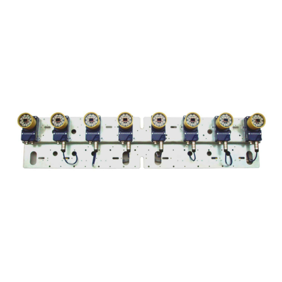
GENERAL VIEW STS400™ Figure A - STS400-0x8 Figure B - STS400-1x8 Figure C - STS400-205, STS400-305 Mounting Slots (4) Reading Windows ID-NET™ Master Positioning Slot ID-NET™ Slaves... -
Page 11: Introduction
The STS400™ provides easy maintenance with a smart solution for fast replacement of any single Matrix 410™ ATS reader. There are a number of STS400™ models which can be chosen to satisfy all the customer needs in terms of: maximum code resolution, conveyor width and depth of field. -
Page 12: Terminology
STS400™ INSTALLATION MANUAL 1.2 TERMINOLOGY The manual will refer to some technical terms when explaining how to choose and install the STS400™. The following table will list the most used. Code Resolution Code Resolution is the width of the narrowest module (element) in a barcode, usually expressed in millimeters. -
Page 13: Sts400™ Feasibility Requirements
INTRODUCTION 1.3 STS400™ FEASIBILITY REQUIREMENTS In order to make the best STS400™ solution choice which fits the application needs, some basic information is required. Highest Application Code Resolution: this data is fundamental for choosing the STS400™ model. This information must be the minimum barcode module among all the barcodes to be read in the application. - Page 14 The Barcode Position Margin takes into account the distance from the Bead where the barcode could be applied. Maximum Conveyor Speed: The STS400™ with factory default configuration can support speeds up to 1 m/s (196.85 fpm, 60 m/min). NOTE: Higher speeds can be obtained by modifying the configuration,...
-
Page 15: Extracting Tire Size From Tire Sidewall Markings
DOF Required [mm] 175.0 Note: Dext is the external tire diameter. Even if this data is not used for the best choice of the STS400™, the above table shows it. It can be calculated as: Dext = Dint + (2 * H). -
Page 16: Sts400™ Model Descriptions
The Reading Features of the various STS400™ models are given in chapter 5. 1.5 POWER REQUIREMENTS The STS400™ solution kit doesn’t include a power supply unit, which has to be ordered separately. The maximum power required depends on the model. -
Page 17: Sts400™ Accessories
1.71 A 16.2 A for 3.5 ms STS400-1x7 2.00 A 21.6 A for 3.5 ms STS400-1x8 2.28 A 21.6 A for 3.5 ms 1.6 STS400™ ACCESSORIES Accessory Description Order No. Power Supplies PG-120-K01 AC/DC Power Supply Kit (EU) 93ACC0046 PG-120-K02... -
Page 18: Installation
STS400™ INSTALLATION MANUAL 2 INSTALLATION 2.1 STS400™ SUPPORTING FRAME STS400™ has been optimized to be mounted on aluminum profiles. A frame made up of aluminum profiles allows the easiest and fastest mounting, and in most cases is the best choice. -
Page 19: Frame Width
If Conveyor Width STS Main Plate then: W = STS Main Plate + (2 * Safe Margin) Note: The STS400-xx7 models require a 70 or 55 mm shift to center the FOV over the conveyor and therefore must be accounted for in the frame width calculation. -
Page 20: Frame Height
STS400™ INSTALLATION MANUAL 2.1.3 Frame Height This is the dimension most influenced by the STS400™ model. The frame profile, indicated as Height (H), is calculated according to the distances shown in the following figure: STS400™ Width STS400™ Reading Distance Conveyor... -
Page 21: Frame Bill Of Materials
INSTALLATION Finally the frame Height (H) can be calculated by the following formula: H = Conveyor Height + Wmin + Max Reading Distance + STS400 Width + Safe Length - Foot Where: Safe Length is an extra length of 50 to 100 mm on the top of the frame, used for fine adjustment at installation time (if needed);... -
Page 22: Mechanical Dimensions
STS400™ INSTALLATION MANUAL 2.2 MECHANICAL DIMENSIONS STS400-004 392.5 [15.45] 182.5 Ø 65.0 [7.19] [5.51] [Ø 2.54] [0.79] [30.91] STS400-005, STS400-205, STS400-305 392.5 [15.45] Ø65.0 112.5 68.6 [Ø2.54] [4.43] [5.51] [2.70] [0.79] [30.91]... - Page 23 INSTALLATION STS400-015 392.5 [15.45] [2.17] Ø65.0 172.5 [Ø2.54] [6.79] [4.33] [0.79] [30.91] STS400-105 392.5 [15.45] Ø100.0 [Ø3.94] 112.5 68.6 [4.43] [5.51] [2.70] [0.79] [30.91]...
- Page 24 STS400™ INSTALLATION MANUAL STS400-115 392.5 [15.45] [2.17] Ø 100.0 172.5 [Ø 3.94] [6.79] [4.33] [0.79] [30.91] STS400-006, STS400-206, STS400-306 392.5 [15.45] 42.5 Ø65.0 [1.67] [5.51] [Ø2.54] [0.79] [30.91]...
- Page 25 INSTALLATION STS400-016 392.5 [15.45] Ø65.0 117.5 [4.63] [4.33] [Ø2.54] [0.79] [30.91] STS400-106 392.5 [15.45] 42.5 Ø100.0 [1.67] [5.51] [0.79] [Ø3.94] [30.91] [31.49]...
- Page 26 STS400™ INSTALLATION MANUAL STS400-116 392.5 [15.45] Ø 100.0 117.5 [Ø 3.94] [4.63] [4.33] [0.79] [30.91] STS400-007 532.5 [20.96] [2.76] Ø65 182.5 [7.18] [5.51] [Ø2.54] [0.79] 1065 [41.93]...
- Page 27 INSTALLATION STS400-017 532.5 [20.96] [2.17] 257.5 Ø65 [10.14] [Ø2.54] [0.79] [4.33] 1065 [41.94] STS400-107 532.5 [20.96] [2.76] Ø100 182.5 [Ø3.94] [7.19] [5.51] [0.79] 1065 [41.93] 1072 [42.22]...
- Page 28 STS400™ INSTALLATION MANUAL STS400-117 532.5 [20.96] Ø 100 257.5 [Ø 3.94] [0.79] [10.14] [4.33] 1065 [41.94] STS400-008 532.5 [20.96] Ø65 42.5 [Ø2.54] [1.67] [5.51] [0.79] 1065 [41.93]...
- Page 29 INSTALLATION STS400-018 532.5 [20.96] Ø65 147.5 [5.81] [4.33] [Ø2.54] [0.79] 1065 [41.94] STS400-108 532.5 [20.96] Ø100 42.5 [1.67] [5.51] [Ø3.94] [0.79] 1065 [41.93] 1080 [42.52]...
-
Page 30: Mounting Distance (Dof)
STS400™ INSTALLATION MANUAL STS400-118 532.5 [20.96] Ø 100 147.5 [Ø 3.94] [5.81] [0.79] [4.33] 1065 [41.94] 2.3 MOUNTING DISTANCE (DOF) 2.3.1 STS400-004, STS400-005, STS400-006, STS400-007, STS400-008 890 mm (35 in) Largest Tire Max. 250 mm (9.8 in) Smallest Tire Conveyor... -
Page 31: Sts400-015, Sts400-016, Sts400-017, Sts400-018
INSTALLATION 2.3.2 STS400-015, STS400-016, STS400-017, STS400-018 710 mm (28 in) Largest Tire Max. 200 mm (7.9 in) Smallest Tire Conveyor 2.3.3 STS400-105, STS400-106, STS400-107, STS400-108 880 mm (34.6 in) Largest Tire Max. 400 mm (15.7 in) Smallest Tire Conveyor... -
Page 32: Sts400-115, Sts400-116, Sts400-117, Sts400-118
STS400™ INSTALLATION MANUAL 2.3.4 STS400-115, STS400-116, STS400-117, STS400-118 930 mm (36.6 in) Largest Tire Max. 380 mm (15.0 in) Smallest Tire Conveyor 2.3.5 STS400-205, STS400-206 Conveyor 317 mm (12.5 in) min nominal DOF DOF range = 317 mm (12.5 in) to 457 mm (18 in) -
Page 33: Sts400-305, Sts400-306
INSTALLATION 2.3.6 STS400-305, STS400-306... -
Page 34: Supporting Profile Height Adjustment
Note: The application DOF is the difference between the maximum tire width and the minimum tire width. If the DOF required by the application is less than the STS400™ nominal DOF, it’s strongly suggested to balance the overlap by keeping the centers of both DOFs coincident: Application In the figure on the right, the STS400™... -
Page 35: Sts400™ Main Plate Mounting
For STS400™ models having an even number of readers, the main plate slot, FOV and operating width are congruent. If the STS400™ model has an odd number of readers then an offset must be applied from the center of the operating width. See... - Page 36 STS400™ INSTALLATION MANUAL Finally the STS400™ can be mounted onto the station frame. The STS400™ has to be installed onto the station frame in the conveyor direction so that the main plate slot (reader side) is aligned with the plate support assembly.
-
Page 37: Sts400™Plate Support Assembly Positioning For Odd Number Of Readers
2.5.1 STS400™Plate Support Assembly Positioning for Odd Number of Readers The STS400™ kits having an odd number of Matrix 410™ ATS readers are the -xx5 or -xx7 models. When mounting one of these models the plate support assembly can’t be fixed exactly over the center of the operating width because the main plate slot no longer corresponds to the center of the FOV. - Page 38 FOV with the center of the conveyor, an offset towards the left side has to be applied: STS400-xx7 with offset over conveyor The positional offset from the operating width center changes according to the STS400™ model used: STS400™ Model...
-
Page 39: Presence Sensor Positioning
INSTALLATION 2.6 PRESENCE SENSOR POSITIONING The STS400™ system comes with a pair of photocells that can be used to detect the presence of the tire on the conveyor and trigger the beginning and the end of the reading phase. When used, they must be positioned and mounted at the conveyor belt level depending on the size of the tires that must be handled. - Page 40 STS400™ INSTALLATION MANUAL In some cases the system can work with only one photocell. If the minimum tire height (H ) is greater than the FOV /2 at the maximum distance, then only a single presence sensor is required and it must be mounted at the mid point of the field...
- Page 41 317 mm (12.5 in), the Vertical FOV is 145 mm (5.7 in). If allowed by the application, it is suggested to use this value for the conveyor gap in order to maximize the reading area. Smaller gaps can be used and maximized by modifying the configuration, please contact your local Datalogic representative for feasibility.
-
Page 42: Electrical Connections
Serial Host: RS232 Outputs: RS485 (optional) RS422 OUT1 OUT2 Figure 3 - STS400™ Array Wiring CBL-1480-02 to CBX500 ATS-001 CAB-MLP-05 to 24 Vdc STS400-1xx models Figure 4 - STS400-1xx Additional Wiring See par. 3.3.1 for wiring illuminator power on STS400-1xx models. -
Page 43: Cbx Connection Box Pinout
ELECTRICAL CONNECTIONS 3.2 CBX CONNECTION BOX PINOUT The STS400™s all connect to the CBX500 ATS-001 as shown in the previous diagram. The table below gives the pinout of the CBX terminal block connectors. CBX500 ATS Terminal Block Connectors Input Power... -
Page 44: Power Supply
Ground Figure 5 - Power Supply Connections For all STS400™ models the power must be 24 Vdc only. See par. 1.5 for recommended power supplies. It is recommended to connect the array CHASSIS to earth ground (Earth) by setting the appropriate jumper in the CBX connection box. -
Page 45: Main Serial Interface
ELECTRICAL CONNECTIONS 3.5 MAIN SERIAL INTERFACE CAUTION: Do not connect to the Main Interface spring clamp terminals if using Host Interface Modules (Fieldbus) with the CBX500. The signals relative to the following serial interface types are available on the CBX spring clamp terminal blocks. -
Page 46: Rs232 Interface
STS400™ INSTALLATION MANUAL 3.5.1 RS232 Interface The RS232 interface can be used for Point-to-Point connections. When it is connected to the host computer it allows both transmission of code data and reader configuration by VisiSet™. The following pins are used for RS232 interface connection:... -
Page 47: Rs485 Full-Duplex Interface
ELECTRICAL CONNECTIONS 3.5.2 RS485 Full-Duplex Interface The RS485 full-duplex (5 wires + shield) interface is used for non-polled communication protocols in point-to-point connections over longer distances (max 1200 m / 3940 ft) than those acceptable for RS232 communications or in electrically noisy environments. The CBX pinout follows: CBX500 ATS Function... -
Page 48: Auxiliary Rs232 Interface
STS400™ INSTALLATION MANUAL 3.6 AUXILIARY RS232 INTERFACE The RS232 auxiliary interface is available for Point-to-Point connections. When it is connected to the host computer it allows both transmission of code data and reader configuration by VisiSet™. The parameters relative to the aux interface (baud rate, data bits, etc.) as well as particular communication modes such as LOCAL ECHO can be defined through the Communication folder of the VisiSet™... -
Page 49: Digital Inputs
ELECTRICAL CONNECTIONS 3.7 DIGITAL INPUTS There are two optocoupled polarity insensitive inputs available on the reader: Input 1 (External Trigger) and Input 2, a generic input: These inputs can be used to control (start/stop) the reading phase: Parameter Reading Phase ON Input Reading Phase OFF Input Source Single Presence Sensor... -
Page 50: Presence Sensor Input Connections
Power Supply Switch inside the CBX. The sensors included in the STS400™ have a standard pinout (brown = +Vdc; blue = GND; black = switched) and can be connected to the Trigger and Input 2 as shown in the figures below. -
Page 51: Input Connections From Plc
ELECTRICAL CONNECTIONS 3.7.2 Input Connections From PLC Alternatively, the reading system can be controlled by a digital output of a PLC. For this purpose, connect the switched signal and the appropriate reference level as shown in the figures below. PLC Signal CBX500 ATS Row 2 Function Input... -
Page 52: Digital Outputs
Function Power Source - Outputs Output 1 + Output 1 - Output 2 + Output 2 - Power Reference Outputs Output Device Power to Output Output device Signal Output device Reference Figure 17 - Open Emitter Output Using STS400™ Power... -
Page 53: Output Connections To External Digital Inputs
Reference Output Signal Figure 18 - Open Collector Output Using STS400™ Power 3.8.2 Output Connections to External Digital Inputs Alternatively, the reading system's digital outputs can be used to control a digital input of another device such as a PLC. For this purpose, connect the switched signal and the appropriate reference level as shown in the figures below. -
Page 54: Display Menus
STS400™ INSTALLATION MANUAL 4 DISPLAY MENUS NOTE: While working on the display the complete reading station is offline. The Offline state means that no readings are performed, no data is transmitted to the PLC and any connection to WebSentinel will be lost. The display menus allow you to: change the messages on the display (View), perform backup and restore, and reset the counters. -
Page 55: Main Menu
DISPLAY MENUS 4.1 MAIN MENU To enter the Menu press the Up and Down buttons simultaneously. The menu structure is shown below. Menu: [Exit] (exits HMI Interface menu) Test Mode Focus/Locate Calibration Code Setting View Extended (enters Extended menu) Extended: [Exit] (returns to Main menu) Backup Yes (performs Backup - uninterruptible) No (returns to Extended menu) -
Page 56: Standard
STS400™ INSTALLATION MANUAL 4.2.1 Standard In this standard view the following content will be shown on the display: Row 1: Reading Result Rows 2 and 3: Code Content Row 4: Number of digits in code and Angle of code in image... -
Page 57: Reading Mask
The percentages range from 00 to 99. On row three (and four which is not used for STS400™), the reading mask for the master and slave readers (ordered from left to right) is shown with the numbers 0 and 1. A... -
Page 58: Init Counters
STS400™ INSTALLATION MANUAL Row 1: Last Reading Result Row 2:Statistics Rows 3 and 4: Reading Mask 1234567890 Good Read G99% N01% M00% P00% Master and 110000000000000 Slave 1 000000000000000 1234567890 Good Read G99% N01% M00% P00% Slave 3 and 000110000000000... -
Page 59: Reading Features
754 (29.7) 0.30 (12) (15) (12.5) (18) (5.7) 937400019 STS400-206 894 (35.2) DOF = Max Reading Distance - Min Reading Distance Guaranteed Reading Volume = FOV x FOV x DOF on Code 128 codes from the Datalogic Test Chart Hmin Vmin... -
Page 60: Hook Chain (Side) Reading Solutions
748 (29.4) 0.30 (12) (19) (15.9) (22) (5.6) 937400021 STS400-306 888 (35) DOF = Max Reading Distance - Min Reading Distance Guaranteed Reading Volume = FOV x FOV x DOF on Code 128 codes from the Datalogic Test Chart Hmin Vmin... -
Page 61: Software Configuration
SOFTWARE CONFIGURATION 6 SOFTWARE CONFIGURATION 6.1 DEFAULT CONFIGURATION The factory default configuration for the STS400™ is given here for reference: MASTER READER CONFIGURATION The following gives an excerpt of the relevant configuration parameters READING SYSTEM LAYOUT: Device Network Setting = Alone o ID-NET ... -
Page 62: Backup & Restore Procedures
(BM100 module) inside the CBX500 ATS connection box. After installation, changes to these parameters must be backed up, overwriting the factory settings. Additionally, backup files can be created for each specific reader on the STS400™ and saved to a PC. -
Page 63: Using Cbx500 Ats Hmi Interface (Keypad/Display)
SOFTWARE CONFIGURATION Backup Procedure 1. Make sure the Write Protection switch (inside the CBX500 ATS) on the BM100 is unlocked. 2. While VisiSet™ is connected to the Master reader, select the Backup item from the Device Menu in confirm by clicking the Yes button. 3. -
Page 64: Maintenance
7 MAINTENANCE 7.1 STS400™: WHAT YOU CAN AND CANNOT DO The STS400™ comes pre-assembled, configured, calibrated and tested. Very few changes may be needed (and are allowed) to adapt the system to the plant operating conditions. Several changes are not permitted and if they are carried out the warranty is automatically void. -
Page 65: Troubleshooting
F1 key, or select Help>Paramters Help from the command menu. If you’re unable to fix the problem and you’re going to contact your local Datalogic office or Datalogic Partner or ARC, we suggest providing (if possible): Application Program version, Parameter Configuration file, Serial Number and Order Number of your reader. -
Page 66: Technical Features
STS400™ INSTALLATION MANUAL 9 TECHNICAL FEATURES ELECTRICAL FEATURES Power Supply Voltage 24 Vdc Consumption See par. 1.5 Communication Interfaces Main - RS232 2400 to 115200 bit/s - RS485 full-duplex 2400 to 115200 bit/s Auxiliary - RS232 2400 to 115200 bit/s ID-NET™... - Page 67 QL100 115 g (4.06 oz) each QL150 123 g (4.34 oz) each To calculate the weight of your specific STS400 model, add the weights of the individual components from those listed above in the quantity present on your model. SOFTWARE FEATURES...
Need help?
Do you have a question about the STS400 and is the answer not in the manual?
Questions and answers