Table of Contents
Advertisement
Quick Links
Advertisement
Table of Contents

Subscribe to Our Youtube Channel
Related Manuals for Datalogic DM3610


Summary of Contents for Datalogic DM3610
- Page 2 DM3610 Reference Manual Ed.: 12/2014 © 2014 Datalogic Automation S.r.l. ALL RIGHTS RESERVED. Protected to the fullest extent under U.S. and international laws. Copying, or altering of this document is prohibited without express written consent from Datalogic Automation S.r.l.
-
Page 3: Table Of Contents
2.4.13 Install the DM3610 Dimensioners ................30 2.4.14 Mounting the DC3000 Dimensioning Controller ............31 2.4.15 Mounting the CBX Connection Box ................31 2.4.16 Mounting the Datalogic Photoelectric Sensor (optional) ..........32 2.4.17 Mounting the Tachometer ..................33 2.4.18 Mounting the Power Supplies ..................34 2.4.19 Install the CD141 Display (optional) ................ - Page 4 3.10.2 Tachometer Wiring (PNP Output) ................45 3.12 Remote Display Wiring ....................46 3.13 Wiring to a Slave DM3610 Dimensioner (HEAD2) Via the CBX510 ......47 3.13.1 Slave DM3610 (NPN) ....................47 3.13.2 Slave DM3610 (PNP) ....................48 3.14 Serial Communication Wiring Through DC3000 Dimensioning Controller ....49 3.15...
- Page 5 5.2.2 Adjust the Skew ...................... 110 Electronically Aligning the System Lasers ............... 111 5.3.1 Adjusting the Field of View and Angle Offset for Each Dimensioner (DM3610 User Interface) ..........................111 Configure the System Using the DC3000 User Interface ......... 114 5.4.1 DC3000 Dimensioning Settings and Calibration (DC3000 User Interface) ....
-
Page 6: References
CBX510 Connection Box Installation Manuals SUPPORT THROUGH THE WEBSITE Datalogic provides several services as well as technical support through its website. Log on to www.datalogic.com and click on the Industrial Automation links for further information: Products - Industrial Automation - Identification Select your product from the links on the Identification page. -
Page 7: Conventions
This product conforms to the applicable requirements of both EN60825-1 and CDRH 21 CFR1040 at the date of manufacture. The DM3610 uses a visible laser diode (red) 658 nm typical, Collimated < 1.5mR, <9.6mW peak power, <1.0mW Average power, Class 3R (IEC60825-1), Class II (CDRH 21CFR1040), in the dimensioning process. -
Page 8: Warning Labels
WARNING LABELS Warning labels indicating exposure to laser light and the device classification are applied onto the body of the DM3610 dimensioner. FRONT VIEW BACK VIEW Figure 1: Warning, Device Class, Warranty Labels NOTE: Warning label used depends on specific product configuration. -
Page 9: Power Supply
POWER SUPPLY This system is intended to be installed by Qualified Personnel only. The DM3610 dimensioner is intended to be supplied by a UL/CE Listed power supply marked SELV (Separated Extra Low Voltage), output rated 24 VDC, minimum 4.0 Amp. - Page 10 This equipment has been tested and found to comply with the limits for a Class A digital device, pursuant to part 15 of the FCC Rules. These limits are designed to provide reasonable protection against harmful interference when the equipment is operated in a commercial environment.
-
Page 11: Introduction
The parcels are scanned while in motion; the scan data is transmitted via Ethernet to the Controller; and the Controller computes the dimension results. A DM3610 head is a complex opto-electrical measurement instrument. When deployed as a standalone device, it is solely responsible for computing parcel dimensions. But, in the Multi- Head Dimensioning System, it is the DC3000 Controller that computes parcel dimensions, and the head’s role is to continuously scan its field of view and measure and transmit... -
Page 12: Dc3000 Dimensioning Controller
TWO-HEAD DIMENSIONING SYSTEM REFERENCE MANUAL 1.2 DC3000 DIMENSIONING CONTROLLER : DC3000 Dimensioning Controller Figure 3 Figure 4: DC3000 Dimensioning Controller Front Panel... -
Page 13: Dm3610 Dimensioner
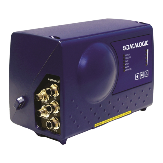
INTRODUCTION Figure 5: DC3000 Dimensioning Controller Rear Panel 1.3 DM3610 DIMENSIONER DM3610 Figure 6: DM3610 Connector Panel Laser Exit Window Laser Safety Label Serial Number Tag Control Panel... - Page 14 TWO-HEAD DIMENSIONING SYSTEM REFERENCE MANUAL Figure 7: Control Panel LED Status Indicators Laser Shutoff/Recovery Button Restore Button Bar Graph LEDs 1-5 Backup Button Figure 8: Connector Panel Ethernet Port 1 Power 24V- - -4A Max Ethernet Port 2 Host...
-
Page 15: Datalogic Photoelectric Sensor
The photoelectric sensor enables a programmable transmit point at a defined distance from the sensor. Without the photoelectric sensor, the DM3610 can be run in continuous trigger mode (see Modify Settings | Tach/Trigger/Transmit in chapter 4). -
Page 16: Cbx Industrial Connection Box
TWO-HEAD DIMENSIONING SYSTEM REFERENCE MANUAL 1.6 CBX INDUSTRIAL CONNECTION BOX CBX Series are industrial connection boxes that can be used to connect the DM3610 to the external display, tachometer, photoelectric sensor, serial devices, relays, or other peripherals. : CBX510 Industrial Connection Box... -
Page 17: Remote Display
The number of displays required per site varies according to certification type. The Datalogic CD141 Remote Display is a 2 line x 20 character vacuum fluorescent display. The display shows the dimensions for the most recent two boxes (with the most recent box on the lower line). -
Page 18: Calibration Boxes
TWO-HEAD DIMENSIONING SYSTEM REFERENCE MANUAL 1.9 CALIBRATION BOXES The DM3610 system requires at least one set of calibration boxes, which aid in system setup and calibration. Two boxes and two margin spacers come with the system in calibration kits in your choice of Metric or Imperial configuration and in the following sizes:... -
Page 19: Mechanical Installation
IMPORTANT: The DM3610 contains electronics that may be affected by electrostatic discharge (ESD). To prevent personal injury or damage to the unit, please follow the safety precautions and warnings found in the References section at the beginning of this manual. -
Page 20: Installation Sequence
Mount the UMB Mounting Plates to the UMBs (if not already installed) Mount the UMBs to the mounting structure Change the default parameters each DM3610 in the system to include a unique name, IP Address, and other parameters (See 2.4.12) Mount the DM3610 dimensioners to their UMBs ... -
Page 21: What You Need To Know About Your Application
MECHANICAL INSTALLATION 2.3 WHAT YOU NEED TO KNOW ABOUT YOUR APPLICATION To assure you get optimal performance out of your Dimensioning System, it must be installed to meet the complete needs of your application. Therefore, take the time to know the details of your application. -
Page 22: Mechanical Installation
The overall dimensions of the DM3610 are provided in section 2.4.6 and chapter 8, Technical Features. The DM3610 is a sealed, unventilated unit. Mounting the unit with 300 mm [12”] of clearance (front, top, and sides) is recommended for ease-of-access and cooling. -
Page 23: General Mounting Guidelines
Avoid staring at the laser light source. While laser light does not constitute a health hazard, staring at the laser for prolonged periods could result in eye damage. As you plan and install your DM3610 dimensioning system application, be sure to keep the following guidelines in mind: ... -
Page 24: Mounting Structure Considerations
It is adjustable enough for you to move your dimensioners to the optimum position for proper dimensioning. It is able to hold 16 kg [36 lbs] (three times the weight of the DM3610) times the total number of dimensioners in your application. - Page 25 MECHANICAL INSTALLATION Figure 15: DM3610 Mounting Dimensions with UMB...
-
Page 26: Mounting The Dimensioners With The Universal Mounting Brackets (Umb)
Mounting the Dimensioners with the Universal Mounting Brackets (UMB) The Universal Mounting Bracket (UMB) allows you to install and make fine adjustments to the position of the DM3610. The bracket assembly includes the UMB, UMB Mounting Plate, and UMB Mounting Disk. Mounting... -
Page 27: Typical Two-Head Application Installations
2.4.8 Typical Two-Head Application Installations You must mount the following components of the two-head dimensioning system before you power it on: Universal Mounting brackets and DM3610 dimensioners DC3000 Controller CBX510 Connection Box Tachometer (if used) Photoelectric Sensor (if used) - Page 28 TWO-HEAD DIMENSIONING SYSTEM REFERENCE MANUAL DM3610 Dimensioners Install height may vary for Laser Lines your application Dimensioners are and is measured offset so lines do to center line of X Shift not cross (X Shift) UMB Mounting Disk Remote Display...
- Page 29 MECHANICAL INSTALLATION Beam DM3610 Catcher HEAD 2 Conveyor Direction Large Box Laser Lines Tachometer X Shift Beam Photoelectric Sensor Catcher (optional) DM3610 HEAD 1 CBX510 Monitor Remote DC3000 (optional) Display Controller (Optional) Figure 19: 2-Head Dimensioning System Installation - TOP VIEW...
-
Page 30: Mounting Structure Assembly
Figure 20: 2-Head Dimensioning System Installation – FRONT VIEW 2.4.9 Mounting Structure Assembly When using the standard mounting structure provided by Datalogic, assemble as defined in the application information provided with the structure. NOTE: This manual addresses standard two-head system installation. The information provided here may be superseded by any application specific drawings provided by Datalogic. -
Page 31: Prepare The Mounting Structure And Universal Mounting Brackets
MECHANICAL INSTALLATION 2.4.10 Prepare the Mounting Structure and Universal Mounting Brackets 1. In standard installations, the DM3610 Universal Mounting Bracket (UMB) is mounted to a short upright mounting support (from mounting structure extrusion). 2. Using a tape measure and marker or pencil, make an installation mark on each upright where the center of the Universal Mounting Bracket (UMB) mounting disks will be located. -
Page 32: Mounting The Umbs
TWO-HEAD DIMENSIONING SYSTEM REFERENCE MANUAL 2.4.11 Mounting the UMBs 1. Position the extrusion to which UMBs will be mounted based on your application drawings. 2. Since applications may vary, the correct mounting position and angle are defined in the application mounting structure drawing. Identify the correct location on the structure and mark the position of the UMB. - Page 33 MECHANICAL INSTALLATION Threaded Inserts Mounting Line Screws Mounting Disk Pitch Angle Adjustment nuts Figure 23: Securing the UMB to the structure Threaded Inserts Mounting Line Screws Mounting Disk Pitch Angle Adjustment nuts Figure 24: Securing the UMB to the structure (Alternate)
- Page 34 TWO-HEAD DIMENSIONING SYSTEM REFERENCE MANUAL 4. Adjust the UMB so that the installation mark is at the center slot of the UMB Mounting Disk, and then secure the mounting disk and bracket with the pitch angle adjustment nuts. Mounting Line Figure 25: Aligning the UMB with the installation mark NOTE: DO NOT over-tighten hardware that holds the UMB in-place.
-
Page 35: Pre-Configuring The Dm3610 Dimensioners
1. Plug the dimensioners in using the power supplies provided. 2. You must configure your PC’s IP Address to be in the same network as the DM3610’s IP Address (example: 192.168.3.1). Set the Netmask to 255.255.255.0 and the Gateway to 0.0.0.0. - Page 36 Software revision should be 1.6(19) or GREATER. 7. Enter a unique name for the dimensioner in the Dimensioner Name field. The master DM3610 should be named “HEAD1” (this dimensioner will be mounted to the left looking downstream), the next DM3610 “HEAD2,” and etc.
- Page 37 14. Set the Pulses per in [cm] to match the application tachometer setting. 15. Set the Trigger Source to Continuous Trigger. 16. Set the Transmit Type to Continuous Scans. (FOR HEAD1 ONLY) Select the Tach Master check box to make this DM3610 the system master dimensioner. 18. Click Update.
- Page 38 TWO-HEAD DIMENSIONING SYSTEM REFERENCE MANUAL 19. In the tree menu under Modify Settings, select Network | Settings. The Network Settings window opens. 20. Adjust the parameters for each head as shown in the table below. Click Update to save the parameters. Dimensioner Name HEAD1 HEAD2...
- Page 39 26. From the drop-down list, select Active High or Active Low to match the polarity of your hardware trigger (Photoelectric Sensor) if the system uses one. 27. Click Update. 28. Power down the DM3610. Repeat the previous configuration steps for each dimensioner in the system.
-
Page 40: Install The Dm3610 Dimensioners
HEAD1 on the left (looking downstream), and then mount the next dimensioner to the right. Set the DM3610 dimensioners on top of each UMB assembly, placing the feet of the DM3610s over the positioning posts on the UMB Mounting Plate. -
Page 41: Mounting The Dc3000 Dimensioning Controller
Figure 29: Mounting the DC3000 Dimensioning Controller 2.4.15 Mounting the CBX Connection Box CBX Series industrial connection boxes can be used to connect the DM3610 dimensioners to the external peripherals. Mount the CBX510 to the mounting structure in a location to facilitate easy access to wiring. -
Page 42: Mounting The Datalogic Photoelectric Sensor (Optional)
TWO-HEAD DIMENSIONING SYSTEM REFERENCE MANUAL 2.4.16 Mounting the Datalogic Photoelectric Sensor (optional) The standard hardware trigger is a Datalogic photoelectric sensor. It works by emitting a light beam that is returned by a simple reflector. When a package breaks the path of light, the trigger signal is activated. -
Page 43: Mounting The Tachometer
The tachometer outputs a set number of pulses for each wheel rotation. This tells the DM3610 the precise conveyor speed, allowing it to determine the exact package position. Because the exact layout of many conveyors is unique, it is impossible to give exact directions for tachometer mounting. -
Page 44: Mounting The Power Supplies
TWO-HEAD DIMENSIONING SYSTEM REFERENCE MANUAL 2.4.18 Mounting the Power Supplies Mount the each power supplies on the structure where its cables can reach both the DM3610 and a power source. Secure the power supply to the mounting structure using the supplied hex screws and drop-in T-nuts as shown below. -
Page 45: Connect Communication And Power Cables To The Installation
2.4.20 Connect Communication and Power Cables to the Installation WARNING: DO NOT connect the power supply to a power source until after all wiring connections have been made to the DM3610, DC3000 and CBX510. Connect all communication cabling for the two-head system as explained in chapter 3, Electrical Installation, including: ... - Page 46 TWO-HEAD DIMENSIONING SYSTEM REFERENCE MANUAL After the DM3610 dimensioners have been installed, they must be calibrated and configured for precise package dimensioning. See chapter 5, for complete procedures for calibrating the system.
-
Page 47: Electrical Installation
Review and plan the communications requirements for your application. IMPORTANT: The content of this manual may be superseded by any customer-specific documentation provided by Datalogic. Before proceeding with any installation procedures, be sure to review ALL documentation, especially content that contains details specific to your installation. -
Page 48: Installation Sequence
ELECTRICAL INSTALLATION. See chapter 2 for mechanical installation details. Most DM3610 applications are shipped with the CBX100 connection box and all the necessary cabling required to electrically install the system. If your system requires custom-length cables or other special wiring, documentation specific to these requirements has been provided in your shipment. -
Page 49: General Electrical Installation Guidelines And Precautions
It is important that you follow these general precautions when installing, setting up, operating, maintaining, troubleshooting or replacing any Datalogic products, parts or related equipment. As you plan and install your two-head dimensioning system, be sure to keep the following guidelines in mind: ... -
Page 50: Power Connections
The CBX510 connection box provides flexible connectivity to a range of I/O devices as well as serial hosting. The Master DM3610 connects to the CBX510 via its I/O port using a single 17-pin M12 to 25-pin D cable. -
Page 51: Cbx510 Connection Box
3.7 CONNECTING A PC TO THE MASTER DM3610 During initial setup, a PC (laptop) may be connected to the Master DM3610 (HEAD1) with an M12 to RJ45 cable. Screw the M12 connector to the HOST port of HEAD1 and plug the RJ45 into the Ethernet port of your PC. -
Page 52: Photoelectric Sensor Connections
The photoelectric sensor is only required if dimension data is transmitted at a certain transmit point. The photoelectric sensor is wired directly into the CBX510. If your application uses a trigger other than the one specified by Datalogic, follow the appropriate wiring diagram to assure proper wiring. -
Page 53: Photoelectric Sensor (Pnp)
ELECTRICAL INSTALLATION 3.9.2 Photoelectric Sensor (PNP) Figure 39: Photoelectric Sensor Wiring (PNP Output) -
Page 54: Tachometer Wiring
TWO-HEAD DIMENSIONING SYSTEM REFERENCE MANUAL 3.10 TACHOMETER WIRING DM3610 applications over a conveyor belt use an accessory tachometer and mounting kit. Use the cable provided with the tachometer to connect to the CBX510 pin block as shown below. 3.10.1 Tachometer Wiring (NPN Output) -
Page 55: Tachometer Wiring (Pnp Output)
ELECTRICAL INSTALLATION 3.10.2 Tachometer Wiring (PNP Output) NOTE: Some tachometers may have a different color coding: Red (+V) or White/Orange White (signal) or White/Blue Black (ground) or Orange/White Figure 41: Tachometer Wiring (PNP Output) -
Page 56: Remote Display Wiring
TWO-HEAD DIMENSIONING SYSTEM REFERENCE MANUAL 3.12 REMOTE DISPLAY WIRING In some Legal-for-Trade applications, a CD141, 40 character remote display may be required. Use the cable provided with the remote display to connect to the CBX510 pin block as shown below. Figure 42: CD141 Remote Display Wiring... -
Page 57: Wiring To A Slave Dm3610 Dimensioner (Head2) Via The Cbx510
CBX510 The Master DM3610 Dimensioner receives Tach/Trig signals through its main I/O cable connected to the CBX510. Slave DM3610 units, however, must be wired directly to the CBX510 pin-block for I/O communication. The following diagram illustrates recommended I/O wiring from slave DM3610s to the CBX510 connection box. -
Page 58: Slave Dm3610 (Pnp)
TWO-HEAD DIMENSIONING SYSTEM REFERENCE MANUAL 3.13.2 Slave DM3610 (PNP) NOTE: Colors are shown for cables 93A050076 (3M), 93A050077 (5M), and 93A050078 (10M), but some installations or spares may use cables 93A050059 (3M), 93A050058 (1M), or 93A050060 (5M). See the color key below:... -
Page 59: Serial Communication Wiring Through Dc3000 Dimensioning Controller
ELECTRICAL INSTALLATION 3.14 SERIAL COMMUNICATION WIRING THROUGH DC3000 DIMENSIONING CONTROLLER The dimensioning system provides serial RS-232/422 communications to other devices through the DC3000 Dimensioning Controller. There is one D-sub 9-pin connector on the front and one on the back panel that provide serial communication. -
Page 60: Checking The Installation
All interconnections should match the application drawings. (Any block diagrams or wiring diagrams provided in this manual are superseded by any customer-specific documentation provided by Datalogic.) The next step is to configure the parameters to meet the needs of your application. -
Page 61: Dc3000 User Interface
Chrome 24.0.1312 (or later) Java Version 7, Update 9 (or later) 4.1.2 Accessing the DC3000 User Interface To access the DC3000 User Interface: 1. Connect your laptop computer to the master DM3610 (HEAD1) HOST port using either the CAB-ETH-M0x M12-IP67 ETHERNET CABLE or CBL-1534-0.2... - Page 62 Properties. e. Select Use the following IP address. In the IP address field, type the first 3 octets of the IP address of the DM3610 unit. g. For the last octet, type a number that differs from the last octet in the DM3610’s IP address.
- Page 63 DC3000 USER INTERFACE If the user ID and password are not valid, the log on screen is presented again with the User ID and Password fields cleared. To log out of the DC3000 User Interface: Click at the upper right corner of the User Interface window to Log Out. When logged out, the Log On window will appear.
-
Page 64: User Interface Basics
TWO-HEAD DIMENSIONING SYSTEM REFERENCE MANUAL 4.3 USER INTERFACE BASICS 4.3.1 DC3000 User Interface Menu Tree The functions that you can select are displayed in a menu tree on the left–hand side of the DC3000 User Interface. The function list is organized much like the hierarchy of a file system, where you can expand items that are preceded by a box to further sub–levels until you find a function of interest. -
Page 65: Modify Settings
DC3000 USER INTERFACE 4.4 MODIFY SETTINGS Use the Modify Settings menu tree selections during initial setup to configure your DM3610 Dimensioner. If necessary, you can later make modifications to the dimensioner’s configuration using the same menu selections, including:... -
Page 66: Modify Settings | Controller Configuration
Controller Model Displays the controller model (DC3000-1200, etc.) Serial Number Displays the 9 character Datalogic serial number of the DC3000 to which the user interface has established a connection. Software Displays the name and revision number of the DC3000 Controller... - Page 67 DC3000 USER INTERFACE Field Name Action/Definition Name/Revision application software. LFT Components Displays the status, name, expected md5 (checksum), and actual md5 (checksum) for the included Legal For Trade components. Configuration Options Units Select Imperial or Metric from the drop-down list. This setting affects the user interface only and not the dimensioning output.
-
Page 68: Modify Settings | System Configuration
Legal For Trade indicates the system is calibrated for certified dimensioning. DM3610’s in this Cluster This display indicates the DM3610 dimensioners that are connected to the system. Each dimensioner’s Online status, Ready status, MAC Address, IP Address, Name, and software Version are displayed. - Page 69 Cluster. 2. Select Replace in this Cluster from the drop-down of the dimensioner you want to use to replace the placeholder shown in DM3610's in this Cluster. The new dimensioner’s information replaces that of the placeholder. 1. Connect a dimensioner’s cables to the system. The...
-
Page 70: Modify Settings | Dimensioning
TWO-HEAD DIMENSIONING SYSTEM REFERENCE MANUAL 4.6 MODIFY SETTINGS | DIMENSIONING Use the Modify Settings | Dimensioning menu tree selections to setup and calibrate the two-head system for certified or non-certified installations. The menu selections include: Settings Calibration 4.6.1 Modify Settings | Dimensioning | Settings Use Dimensioning | Settings to turn certification mode on or off, set dimension resolution, and define package size requirements. - Page 71 DC3000 USER INTERFACE 2. Enter the appropriate information in the form as described below. Field Name Action/Definition Outputs Units Select inch or mm from the drop-down list. Once the window is updated, the dimensions displayed on this window will be displayed in the unit type selected.
- Page 72 TWO-HEAD DIMENSIONING SYSTEM REFERENCE MANUAL Field Name Action/Definition Certification Mode Select On or Off from the drop-down list. Turn certification mode certified Legal-for-Trade applications. Turning certification mode on causes most of the input fields in the Dimensioning Settings, Dimensioning Calibration, Configuration, and Tach/Trigger windows to be disabled (see below).
-
Page 73: Modify Settings | Dimensioning | Calibration
DC3000 USER INTERFACE 4.6.2 Modify Settings | Dimensioning | Calibration Use Dimensioning | Calibration to calibrate an installed DM3610 dimensioner. To calibrate the dimensioner (See also, Dimensioner Calibration in chapter 5, Dimensioning Features): 1. In the tree menu under Modify Settings, navigate to Dimensioning | Calibration. - Page 74 TWO-HEAD DIMENSIONING SYSTEM REFERENCE MANUAL 2. Enter the appropriate information in the form as described below. Field Name Action/Definition Belt Analysis Side Margins Side margins equal the width of spacers (the wooden blocks shown in the drawing below) that help the dimensioner find the edges of the conveyor belt.
- Page 75 DC3000 USER INTERFACE Field Name Action/Definition HEAD 2 HEAD 1 Side Margins for HEAD 1 (Outside) Side Margins for HEAD 2 (Outside) Figure 48: Side Margin Spacer Placement (Outside)
- Page 76 TWO-HEAD DIMENSIONING SYSTEM REFERENCE MANUAL Field Name Action/Definition Belt Analysis Head Pitch Enter Head Pitch Estimate 1 (HEAD1) and Head Pitch Estimate 2 Estimate 1 and 2 (HEAD2) based on the angles from the application specifications. This will be a positive degree integer for each head (no negative degree indication).
- Page 77 DC3000 USER INTERFACE Field Name Action/Definition Use Belt Click Use Belt to transfer the "found" or calculated dimensions to the Dimensioning Area fields. The values are highlighted in yellow until the page has been updated. Dimensioning NOTE: All these values, except for the X Shift, Area are automatically populated by the Find Belt/Use Belt commands...
- Page 78 TWO-HEAD DIMENSIONING SYSTEM REFERENCE MANUAL X Shift Enter the measured distance on the belt from DM3610 HEAD1 scan line to HEAD2 scan line. Direction of Travel HEAD 2 HEAD 1 Downstream X Shift 0.000 HEAD 2 X Shift 1. Enter 0.000 for the X Shift of HEAD1.
-
Page 79: Modify Settings | Tach/Trigger/Transmit
1. In the tree menu under Modify Settings, navigate to Tach/Trigger/Transmit. The Tach/Trigger/Transmit window opens. NOTE: The information entered here supersedes the data entered in the Tach/Trigger/Transmit page of the DM3610 User Interface for each individual dimensioner. WARNING: Individual DM3610 dimensioners must be set to... - Page 80 TWO-HEAD DIMENSIONING SYSTEM REFERENCE MANUAL Field Name Action/Definition Tachometer Pulse per Enter the number of tachometer pulses used per cm [in] cm [in] traveled. Tach Scale Enter a factor to eliminate deviations in the expected versus Factor actual tachometer pulses/inch or cm. For example: If you notice that the length (in the direction of travel) of your package is too short and you have a tachometer pulse of 16 pulses per inch, enter a Tach Scale...
- Page 81 DC3000 USER INTERFACE Field Name Action/Definition Trigger Enter the distance from your trigger source to the DM3610 Reference HEAD1 laser scan line. Point Direction of Travel Trigger Reference Point value Software Trigger Software Select Host - 1, Host - 2, Net - 1, or Net - 2 from the drop- Trigger down list.
- Page 82 TWO-HEAD DIMENSIONING SYSTEM REFERENCE MANUAL Field Name Action/Definition Continuous When selected, the dimensioner is always in trigger mode Trigger and immediately transmits the dimensions of any package seen. Transmit Transmit is hidden if Continuous Trigger is selected as the trigger source. Transmit Specifies which edge of the package (leading or trailing) is used to reference Edge...
-
Page 83: Modify Settings | Network
DC3000 USER INTERFACE 4.8 MODIFY SETTINGS | NETWORK Use Modify Settings | Network to specify network settings (including the IP address) for the dimensioner. Net Host Connection 1 and Net Host Connection 2 define two network connections for sending messages. The Connection Type and Message Format for each port can be set independently. -
Page 84: Modify Settings | Network | Network Settings
TWO-HEAD DIMENSIONING SYSTEM REFERENCE MANUAL 4.8.1 Modify Settings | Network | Network Settings Use Modify Settings | Network | Network Settings to specify network settings (including the IP address) for the dimensioner. Net Host Connection 1 and Net Host Connection 2 define two network connections for sending messages. - Page 85 DC3000 USER INTERFACE 2. Enter the appropriate information in the form as described below. Field Name Action/Definition Enable DHCP Select this box to enable DHCP (Dynamic Host Configuration Protocol.) If selected, the system gets the IP Address, Net Mask, and Gateway IP Address from a DHCP server. When selected, the manual entry fields for these protocols will not be available.
- Page 86 When Custom Message selected, editable fields in the Message Definition #n window may be defined by the custom software installed. Standard Message: When Standard Message is selected, the system uses a message format as defined by the standard DM3610 software.
- Page 87 DC3000 USER INTERFACE Field Name Action/Definition NOTE: When Standard Message selected, no user input is permitted in the Message Definition #n window. User Defined Message: This selection allows the user to define messages used. Messages can be defined in the Message Definition #n window.
-
Page 88: Modify Settings | Network | Message Definition #N
TWO-HEAD DIMENSIONING SYSTEM REFERENCE MANUAL 4.8.2 Modify Settings | Network | Message Definition #N Use Modify Settings | Network | Message Definition #n to define messages when User Defined Messages has been selected in the Network Settings window. To define the appearance of dimensioner messages: 1. - Page 89 DC3000 USER INTERFACE 2. Enter the appropriate information in the form as described below. Field Name Action/Definition Framing Define the message framing Header Enter a character string for the header (ASCII or Hex). These characters will be sent at beginning of every message. Up to 25 characters are allowed.
- Page 90 TWO-HEAD DIMENSIONING SYSTEM REFERENCE MANUAL Field Name Action/Definition Field Width Select the field width of the minimal number of characters for length, width, and height from the drop-down list. 2 to 7 characters are available. If the value has fewer characters than the field width, it will be padded with zeros on the left.
- Page 91 Format: 00:0e:13:05:00:01nnnnnnnnnn-YYYYMMDDhhmmss NOTE: Alibi is only available for controller model DC3000-1200 (OIML) and dimensioner model DM3610-3200 (OIML). Append Volume Select the check box to enable. When checked, Volume Units, Volume Field Width, and Volume Precision drop-down boxes are revealed. Select cubic Volume Units from the drop-down list. Selections include in³...
- Page 92 TWO-HEAD DIMENSIONING SYSTEM REFERENCE MANUAL Field Name Action/Definition Heart Beat Time Enter an interval for heart beat time out in milliseconds. Out (0-30,000 0 = Disable Heart Beat Message, 1-30,000 = Delay before sending Heart Beat Message 3. When you have finished making changes, click Update to save or click Reset to revert to the previously saved values.
-
Page 93: Modify Settings | Serial
DC3000 USER INTERFACE 4.9 MODIFY SETTINGS | SERIAL Use Modify Settings | Serial to specify serial settings for the dimensioner. Port #1 and Port #2 define two serial connections for sending messages. The Connection Type and Message Format for each port can be set independently. The menu selections include: Port #1 Port #2 Message Definition #1... - Page 94 TWO-HEAD DIMENSIONING SYSTEM REFERENCE MANUAL 2. Select the appropriate information in the form as described below. Field Name Action/Definition Baud Rate Select a baud rate from the options provided (signal events per second). Data Bits Select the number of data bits from the options provided (bits per second). Stop Bits Select the number of stop bits from the options provided.
-
Page 95: Modify Settings | Serial | Message Definition #N
DC3000 USER INTERFACE 4.9.2 Modify Settings | Serial | Message Definition #N Use Modify Settings | Serial | Message Definition #n to define messages when User Defined Messages has been selected in the Serial Port #n window. To define the appearance of dimensioner messages: 1. - Page 96 TWO-HEAD DIMENSIONING SYSTEM REFERENCE MANUAL 2. Enter the appropriate information in the form as described below. NOTE: Available user interaction with this form will vary depending on the Message Format selected in Modify Settings | Serial | Port #n. Field Name Action/Definition Framing Define the message framing...
- Page 97 DC3000 USER INTERFACE Field Name Action/Definition Dimensions Select in what order you would like the Length, Width, and Height Format measurements to appear in the message. L=Length / W=Width / H=Height Field Width Select the field width of the minimal number of characters for length, width, and height from the drop-down list.
- Page 98 10 digit sequence number, dash, then 14 char date/time. Format: 00:0e:13:05:00:01nnnnnnnnnn-YYYYMMDDhhmmss NOTE: Alibi is only available for controller model DC3000-1200 (OIML) and dimensioner model DM3610-3200 (OIML). Append Select the check box to enable. When checked, Volume Units, Volume Volume Field Width, and Volume Precision drop-down boxes are revealed.
-
Page 99: Modify Settings | Logging Options
Debug (1-4) WebManager Log Enables NOTE: Changes to these settings should be avoided unless requested by Datalogic. 2. When you have finished making your selections, click Update to save or click Reset to revert to the previously saved selections. -
Page 100: Modify Settings | Save / Retrieve
TWO-HEAD DIMENSIONING SYSTEM REFERENCE MANUAL 4.12 MODIFY SETTINGS | SAVE / RETRIEVE Use Save/Retrieve to save all the settings to the dimensioner and backup the settings to the backup module and/or file. To use the Save/Retrieve functions: 1. In the tree menu under Modify Settings, navigate to Save/Retrieve. The Save/Retrieve window opens. - Page 101 DC3000 USER INTERFACE Field Name Action/Definition Or, right click and select Save as or Save link as to save the XML file to your computer. Load Default Click Load Default Parameters to apply the default software Parameters parameters to the system. To load an XML 1.
- Page 102 TWO-HEAD DIMENSIONING SYSTEM REFERENCE MANUAL Field Name Action/Definition Clear Logs Click this button to clear (delete) all saved log files. A warning dialog appears. Click OK to clear the logs, or click Cancel to return to the Save/Retrieve window. Reboot DC3000 Click Reboot to re-initialize the system.
-
Page 103: Modify Settings | Inscription (Oiml Certified Applications Only)
DC3000 USER INTERFACE 4.13 MODIFY SETTINGS | INSCRIPTION (OIML CERTIFIED APPLICATIONS ONLY) The inscription window provides an electronic label for OIML certified systems. IMPORTANT: This window is only to be modified by the certification inspector for the Notifying Body. To use the Inscription function: 1. - Page 104 TWO-HEAD DIMENSIONING SYSTEM REFERENCE MANUAL 4. Click OK. The Notifying Body number is displayed in the white text field.
-
Page 105: Diagnostics
DC3000 USER INTERFACE 4.14 DIAGNOSTICS Use the Diagnostics menu tree selections to monitor your dimensioning system performance, view system messages, update the dimensioner firmware, and access online help. The Diagnostic windows include:... -
Page 106: Diagnostics | Monitor
TWO-HEAD DIMENSIONING SYSTEM REFERENCE MANUAL 4.14.1 Diagnostics | Monitor Use the Diagnostics | Monitor as the primary tool to monitor the dimensioner's operation and system information in real-time. Status indicators and vital statistics appear on a single screen, enabling you to effectively and efficiently detect and troubleshoot any problems that may occur. - Page 107 DC3000 USER INTERFACE 2. View system information and interact with the Monitor as described below. Field Name Action/Definition System Status Network (1-2) – GREEN indicates connection to an active host. Blank/Gray indicates there is no active connection. Tach – GREEN indicates the tachometer input.
- Page 108 TWO-HEAD DIMENSIONING SYSTEM REFERENCE MANUAL Field Name Action/Definition Option Buttons Select an option button for None, Serial Port 1, Serial Port 2, Net Port 1, or Net Port 2 to view messages for that connection. Connect Click Connect to re-establish communications between the Monitor page and the DC3000.
-
Page 109: Diagnostics | Dimview
DC3000 USER INTERFACE 4.14.2 Diagnostics | DimView Use the Diagnostics | DimView to view a graphical representation of the dimension point information captured for a package. 1. In the tree menu under Diagnostics, click DimView. The DimView window opens. 2. Select the check box next to the heads you want to display. - Page 110 TWO-HEAD DIMENSIONING SYSTEM REFERENCE MANUAL The DimView monitor is explained in the image below. Figure 49: Understanding DimView 3. When you have selected the heads to display, click Play to activate DimView or click Pause to freeze the image.
-
Page 111: Diagnostics | Log Viewer
DC3000 USER INTERFACE 4.14.3 Diagnostics | Log Viewer The Diagnostics | Log Viewer lets you review the performance logs saved by the dimensioner. To View the Log Viewer: 1. In the tree menu under Diagnostics, click Log Viewer. The Log Viewer window opens. -
Page 112: Diagnostics | Audit And Alibi
TWO-HEAD DIMENSIONING SYSTEM REFERENCE MANUAL 4.14.4 Diagnostics | Audit and Alibi Use Diagnostics | Audit and Alibi to search for and view system audit trail and alibi logs. To View Audit and Alibi: 1. In the tree menu under Diagnostics, click Audit and Alibi. The Audit and Alibi window opens. - Page 113 DC3000 USER INTERFACE Field Name Action/Definition Logging Options Audit Trail Log: Opens the Audit Trail Log for viewing in the Log File (Dimensioning- section of the screen. Results are scrollable. specific) Alibi Storage Log: Opens the Alibi Storage Log for viewing in the Log File section of the screen.
-
Page 114: Diagnostics | Software Install
Use Diagnostics | Software Install to download software from or to install software to the DC3000 Dimensioning Controller. CAUTION: This function should only be performed under the guidance of Datalogic Technical Support. To use the Software Install functions: In the tree menu under Diagnostics, navigate to Software Install. The Software Install window opens. - Page 115 DC3000 USER INTERFACE 3. Click Install Software. A progress indicator appears. 4. When the software has been installed, the following graphic appears.
-
Page 116: Diagnostics | Help
TWO-HEAD DIMENSIONING SYSTEM REFERENCE MANUAL 4.14.6 Diagnostics | Help Clicking Diagnostics | Help opens the full online help system for the DM3610 User Interface. You can use the Contents, Index, and Search options of the online help system to find... -
Page 117: Dimensioning Setup And Calibration
Training is available through specific Service Programs and Maintenance Agreements. See our website at www.datalogic.com. 5.1 SYSTEM SETUP Install the structure, Universal Mounting Brackets (UMBs), DM3610 dimensioners, DC3000 Dimensioning Controller and other equipment as indicated in chapter 2, Mechanical Installation. -
Page 118: Adjust The Tilt And Skew Of The Dm3610 Dimensioners
2. While keeping the test box aligned with the conveyor, adjust its position until the laser is just touching the edge of the box. The goal is to adjust the alignment of the DM3610 until the laser is parallel to the edge of the test box. - Page 119 DIMENSIONING SETUP AND CALIBRATION 3. To adjust the laser tilt, loosen the screws securing the UMB Mounting Plate to the UMB and using a flathead screwdriver carefully pry the plate back and forth until the laser is exactly parallel to the edge of the test box. When adjusted correctly, tighten the UMB Mounting Play screws.
-
Page 120: Adjust The Skew
TWO-HEAD DIMENSIONING SYSTEM REFERENCE MANUAL 5.2.2 Adjust the Skew To adjust the laser skew, loosen the screws securing the front of each UMB to its back and use a flathead screwdriver to carefully pry the front of the UMB up and down using the adjustment slots until the laser is exactly 90°... -
Page 121: Electronically Aligning The System Lasers
DM3610 User Interface to cover its portion of the dimensioning area over the conveyor. Perform the following adjustments for each DM3610: 1. Configure your laptop PC’s IP Address to be in the same network as the DM3610’s IP Address (example: 192.168.3.1) See section 4.1.2. - Page 122 TWO-HEAD DIMENSIONING SYSTEM REFERENCE MANUAL 6. Adjust the three following parameters in the DM3610 User Interface for each dimensioner in Modify Settings | Dimensioning | Calibration: Set Scan Points to 900 (default) unless authorized by Datalogic. Field of View: Adjust FOV to cover largest system boxes at edges of conveyor.
- Page 123 DIMENSIONING SETUP AND CALIBRATION To adjust the Field of View and Angle Offset (Viewing Downstream): 1. Starting with HEAD1, place the tallest box defined by the application on the side of the belt furthest from HEAD1. 2. Change the Field of View of HEAD1 to 20, and click Update. 3.
-
Page 124: Configure The System Using The Dc3000 User Interface
3. Open a browser and enter an IP address of 192.168.3.70. The DC3000 User Interface opens. 4. Log on to the DC3000 User Interface. The default User ID is DM3610, and default Password is DM3610. NOTE: For a detailed description of the DC3000 User... - Page 125 DIMENSIONING SETUP AND CALIBRATION 5. From the menu tree under Modify Settings, select Controller Configuration. The Controller Configuration window opens. 6. Make sure Controller Model and Software Name/Revision are correct for your application.
- Page 126 The DM3610’s not in this Cluster field identifies units that have been located but have not yet been included into the Multi-Headed system network. 8. In the Action drop-down list of the DM3610’s not in this Cluster section, select Replace for HEAD1 and HEAD2.
-
Page 127: Dc3000 Dimensioning Settings And Calibration (Dc3000 User Interface)
DIMENSIONING SETUP AND CALIBRATION 9. Click Update. The HEAD1 and HEAD2 should now have replaced the placeholder listed under DM3610’s in this cluster. 5.4.1 DC3000 Dimensioning Settings and Calibration (DC3000 User Interface) 1. In the menu tree under Modify Settings, select Dimensioning | Settings. The Dimensioning | Settings window opens. - Page 128 Legal for Trade applications in both the DC3000 Dimensioning Controller DM3610 dimensioning heads. 4. Lay pieces of white paper across the conveyor under the laser lines to avoid any irregularities in the conveyor belt from affecting the data.
- Page 129 IMPORTANT: Only one side margin is placed in the laser beam for each DM3610. One in the laser beam of HEAD1 at the far edge of the conveyor, and one for HEAD2 at the far edge of the conveyor, as shown in the illustrations below.
- Page 130 TWO-HEAD DIMENSIONING SYSTEM REFERENCE MANUAL HEAD 2 HEAD 1 Side Margins for HEAD 1 (Outside) Side Margins for HEAD 2 (Inside) Figure 57: Spacer placement 7. Enter Head Pitch Estimate 1 (HEAD1) and Head Pitch Estimate 2 (HEAD2) based on the angles from the application specifications.
- Page 131 DIMENSIONING SETUP AND CALIBRATION 8. Click Find Belt. Dimensioning parameters are automatically loaded into the Dimensioning Area. 9. Click Use Belt. The Find Belt parameters are accepted. 10. Enter 0.000 for the X Shift of HEAD1. 11. Measure the X Shift distance between the scan lines from HEAD1 to HEAD2. This number will be positive.
-
Page 132: Tach/Trigger/Transmit (Dc3000 User Interface)
TWO-HEAD DIMENSIONING SYSTEM REFERENCE MANUAL 5.4.2 Tach/Trigger/Transmit (DC3000 User Interface) Use Tach/Trigger/Transmit to set up the tachometer source and trigger source. A range of settings are definable based on use of hardware or software sources (see section 4.7). 1. In the menu tree under Modify Settings, select Tach/Trigger/Transmit. The Tach/Trigger/Transmit window opens. - Page 133 DIMENSIONING SETUP AND CALIBRATION 3. Click Update. 4. In Modify Settings | Tach/Trigger/Transmit, make sure: Trigger Source is set to Application Specifications Pulse per in [cm] (16ppi [6.4 pulses per cm] or 20ppi [8 pulses per cm] should be set to match the tachometer switch setting NOTE: The trigger reference point is in reference to HEAD1 regardless of where HEAD2 is located (upstream...
-
Page 134: Dynamic Calibration
TWO-HEAD DIMENSIONING SYSTEM REFERENCE MANUAL 5.5 DYNAMIC CALIBRATION After you have set up the dimensioning settings and calibration in the DC3000 User interface, you must check the accuracy of the system by running test boxes through the system. Dimensions returned when a box is run through the system must fall below the outside tolerance required by your application. - Page 135 Run test boxes and make adjustments until the width falls within system tolerance. 5. After the calibration process has been completed, save parameters from each DM3610 and the DC3000 Dimensioning Controller to the laptop computer. This is done using Modify Settings | Save/Retrieve in DM3610 User Interface and DC3000 User Interface.
-
Page 136: Dimensioning Irregular-Shaped Packages
TWO-HEAD DIMENSIONING SYSTEM REFERENCE MANUAL 5.6 DIMENSIONING IRREGULAR-SHAPED PACKAGES The DM3610 Two-Head Dimensioning System provides the dimensioning of irregular-shaped packages. When an irregular-shaped package (irregulars) passes through the dimensioning area, the system determines the smallest possible cuboidal dimensions of the package (length, width, and height) and creates a virtual bounding box around it. - Page 137 DIMENSIONING SETUP AND CALIBRATION To determine the cuboidal dimensions of an irregular-shaped package: 1. Place the test package on a flat surface. 2. Establish a baseline edge using a straightedge. Straightedge Baseline Figure 61: Establish a baseline against a straightedge 3.
- Page 138 TWO-HEAD DIMENSIONING SYSTEM REFERENCE MANUAL 4. With the delimiters in place along the baseline straightedge, measure between the edges of the delimiters and diagonally as shown to make sure they are parallel. The measurements must be equal. Then, when the delimiters are parallel, measure the distance between them to determines the length (L) of the package.
- Page 139 DIMENSIONING SETUP AND CALIBRATION 6. Next, use a level to determine the height (H) of the package. Rest one end of the level at the highest spot on top of the package, and then, when the bubble or digital readout indicates level, measure form the bottom of the level to the surface on which the package is resting.
-
Page 140: Maintenance
There are no user serviceable parts within the DC3000 Dimensioning Controller or DM3610 Dimensioner. DO NOT OPEN THE UNITS. Opening the device may void its warranty. CAUTION: Proceeding with any setup, calibration, or service procedures without proper training may void the warranty. -
Page 141: Maintenance Tasks
3. Carefully remove any debris in or around the exit window of the DM3610 Dimensioner. 4. Wipe the exterior of the DM3610 Dimensioner (except the exit window) with a clean, soft cloth dampened slightly with a mild detergent solution. 5. The of the DM3610 Dimensioner exit window should be cleaned after this task is... -
Page 142: Cleaning The Of The Dm3610 Dimensioners' Exit Windows
Cleaning the of the DM3610 Dimensioners’ Exit Windows WARNING: Shut down the DM3610 before performing this maintenance task. Do not stare into the DM3610’s exit window at the laser light. Avoid direct eye exposure. The laser light level does not constitute a health hazard, however staring at the laser light for prolonged periods could result in eye damage. -
Page 143: Cleaning The Photoelectric Sensor
1. Turn off the product transport. 2. Turn off the DM3610 by disconnecting the power source. 3. Clean the photoelectric sensor’s lens using the denatured alcohol solution and a cotton swab or lens paper. -
Page 144: Cleaning The Tachometer
1. Turn off the product transport. 2. Turn off the DM3610 by disconnecting the power source. 3. Using a clean, soft cloth, wipe the wheels of the tachometer clean using a mild detergent solution. -
Page 145: Tighten Mounting Hardware
3. If the photoelectric sensor’s LED does not change status, adjust the photoelectric sensor so that it is properly aligned with the reflector. 4. If the TRIGGER LED on the DM3610 is not green when the photoelectric sensor’s beam is blocked, check the cabling between the photoelectric sensor... -
Page 146: Verify Tachometer Operation
6.2.9 Verify Tachometer Operation 1. Rotate the tachometer wheel. 2. The TACH LED on the DM3610’s connector panel should flash indicating the tachometer is operational. 3. If the TACH LED does not flash when the tachometer wheel is rotated, check... -
Page 147: Troubleshooting
IMPORTANT: Due to the complex and application-specific nature of dimensioning / certified dimensioning installations, operational deficiencies of the DM3610 must be diagnosed and serviced by a trained and authorized Datalogic technician. There are no user serviceable components or field replaceable units (FRUs) inside the DM3610. -
Page 148: Dc3000 Dimensioning Controller Error Codes And Resolutions
NOTE: The following error codes pertain to a DC3000 Dimensioning Controller using certified dimensioning. If the DC3000 is providing volume information only, some of these codes do not apply. For DM3610 HEAD errors, see the DM3610 Dimensioner Reference Manual. BOX_NODIM_UNKNOWN,... -
Page 149: Technical Features
PHYSICAL FEATURES L 267 mm [10.5”] x W 174 mm [7.0”] x H 124 mm [5.0”] Overall Dimensions Weight 4.0 kg [8.8lb] Enclosure DM3610 Dimensioner ELECTRICAL FEATURES Power 24VDC +/- 10% Requirements Power Consumption 19 W Average (75 W Max) based on 600 scans/second... - Page 150 5.5 kg [12 lbs.] Enclosure IP 65, Aluminum OPTIONS AND WARRANTY Options Side-by-side package detection, irregulars, out-of-gauge detection Service Options Installation services and on-site training Warranty 2-year limited, parts and labor The latest product documentation can be downloaded from our website, www.datalogic.com.
-
Page 152: Index
Dimensions, Clearance, 12 Tachometer Wiring, 44, 46 DimView Wiring, 41 Diagnostics, 99 CBX Industrial Connection Box, 6 Understanding, 100 CBX510, 6 DM3610, 3 CD141, 7 Pre-Configuring, 25 CE Compliance, vii DWS System, 5 Checking Installation, 50 Dynamic Calibration, 124 Cleaning... - Page 153 Connection Box, 31 Tightening, 135 Controller, 31 Mounting Structure, 14, 20 DC3000 Dimensioning Controller, 31 Dimensioner, 30 Display, 34 Net Mask Installing the DM3610 Dimensioners, 30 Definition, 73 Introduction, 1 Network IP Address Message Definition, 78 Default, 52 Network Settings, 74...
- Page 154 LED status indicator, 42 disconnect device, readily accessible, 40 Troubleshooting, 137 requirements, 40 Power Supply, vii Mounting, 34 Pre-Configuring the DM3610 Dimensioner, UL Listing, vii UMB, 16 Preparing for Electrical Installation, 37 Mountng, 22 Preparing for Mechanical Installation, 9 Unit Dimensions, 12...
- Page 155 Guidelines, 39 Sequence, 38 Photoelectric Sensor, 42 Serial Communication, 49 power quick-disconnect requirement, 39 Slave Dimensioner, 47, 48 Precautions, 39 Tachometer, 44 safety ground, 39, 40...
Need help?
Do you have a question about the DM3610 and is the answer not in the manual?
Questions and answers