Datalogic Matrix 320 Product Reference Manual
Image based industrial reader
Hide thumbs
Also See for Matrix 320:
- Product reference manual (188 pages) ,
- Quick start manual (2 pages)
Table of Contents
Advertisement
Advertisement
Table of Contents

Related Manuals for Datalogic Matrix 320


Summary of Contents for Datalogic Matrix 320
- Page 1 Matrix 320™ PRODUCT REFERENCE GUIDE Image Based Industrial Reader...
- Page 2 Electronic versions of this document may be downloaded from the Datalogic website (www.datalogic.com). If you visit our website and would like to make comments or suggestions about this or other Datalogic pub- lications, please let us know via the "Contact" page.
-
Page 3: Table Of Contents
LED Safety ........................xi HANDLING .......................XII GENERAL VIEW .......................XIV Matrix 320 (LIquid Lens) with 14 LEDs Illuminator ............xiv Matrix 320 (LIquid Lens) with 36 LEDs Illuminator ............xv Matrix 320 (C-Mount) without Illuminator ..............xvi Matrix 320 (C-Mount) with 36 LEDs Illuminator ..............xvii RAPID CONFIGURATION.................... - Page 4 Matrix 320 C-Mount Mounting Instructions ..............68 Mounting Instructions for Matrix 320 C-Mount without illuminator ..........68 Mounting instructions for Matrix 320 with 36 LED illuminator ............70 Heat Sink mounting instructions ...................... 72 When to mount the heat sink ....................72 How to mount the heat sink .....................
- Page 5 Input 2 Connections Using External Power ..................96 Input 3 Connections (CBX500 Only) ....................96 Outputs ......................... 97 Output 1 and 2 Connections Using Matrix 320 Power ..............98 Output 1 and 2 Connections Using External Power .................99 Output 3 Connections Using Matrix 320 Power (CBX500 Only) ............100 Output 3 Connections Using External Power (CBX500 Only) ............100...
- Page 6 Standard Illuminators for Manual Adjustable Focus Models (C-Mount) ......176 36 LEDs Illuminator ........................176 Polarizer ........................177 Direct Part Marking Applications ................... 180 Matrix 320 Recommended Illumination ................181 Color Contrast Considerations ....................... 182 MAINTENANCE ...................... 184 Cleaning ........................184 TROUBLESHOOTING ....................
-
Page 7: Preface
TECHNICAL SUPPORT Support Through the Website Datalogic provides several services as well as technical support through its website. Log on to (www.datalogic.com). For quick access, from the home page click on the search icon , and type in the name of the product you’re looking for. -
Page 8: Reseller Technical Support
PREFACE Reseller Technical Support An excellent source for technical assistance and information is an authorized Datalogic reseller. A reseller is acquainted with specific types of businesses, application software, and computer systems and can provide individualized assistance. viii MATRIX 320... -
Page 9: Compliance
Datalogic commercial reference contacts. Since April 20th, 2016 the main European directives applicable to Datalogic products require inclusion of an adequate analysis and assess- ment of the risk(s). This evaluation was carried out in relation to the applicable points of the standards listed in the Declaration of Conformity. -
Page 10: Laser Safety
The following warning label content is applied to each of the laser equipped products indicated in the General View illustration (Figure 1). Example Laser Warning Labels for Matrix 320 Liquid Lens models Example Laser Warning Labels for Matrix 320 C-Mount models with 36 LED illuminator Produit(s) conforme selon 21CFR 1040.10 sauf des dérogations relatives à... -
Page 11: Led Safety
LED SAFETY LED SAFETY According to EN 62471:2010, for all Datalogic Matrix 320 compatible internal illumina- tors, LED emission is classified into Risk Group 1, except Matrix 320 with UV illuminator which is Risk Group 3. PRODUCT REFERENCE GUIDE... -
Page 12: Handling
HANDLING Matrix 320 is designed to be used in an industrial environment and is built to withstand vibration and shock when correctly installed, however it is also a precision product and therefore before and during installation it must be handled correctly to avoid damage. - Page 13 • do not weld the reader into position which can cause electrostatic, heat or reading window damage. • do not spray paint near the reader which can cause reading window damage. Products using liquid lens technology are sensitive to UV light and will be damaged if exposed to UV illumination.
-
Page 14: General View
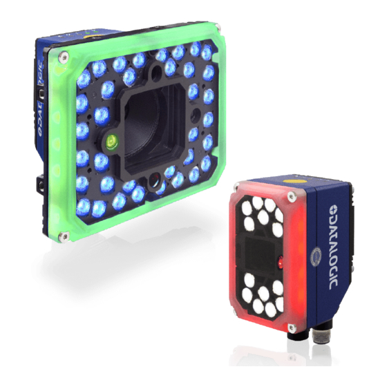
GENERAL VIEW MATRIX 320 (LIQUID LENS) WITH 14 LEDs ILLUMINATOR Figure 1 - Matrix 320 with 14 LEDs illuminator 1. Lens Cover 9. Bracket Mounting Holes (4) 2. HMI X-PRESS Interface 10. Ethernet Connection LED 3. Green Spot 11. Power - COM - I/O Connector 4. -
Page 15: Matrix 320 (Liquid Lens) With 36 Leds Illuminator
MATRIX 320 (LIQUID LENS) WITH 36 LEDS ILLUMINATOR MATRIX 320 (LIQUID LENS) WITH 36 LEDs ILLUMINATOR Figure 2 - Matrix 320 with 36 LEDs illuminator 1. HMI X-PRESS Interface 9. Bracket Mounting Holes (4) 2. Lens Cover 10. Ethernet Connector 3. -
Page 16: Matrix 320 (C-Mount) Without Illuminator
GENERAL VIEW MATRIX 320 (C-MOUNT) WITHOUT ILLUMINATOR Figure 3 - Matrix 320 without illuminator 1. HMI X-PRESS Interface 6. Power On LED 2. Base Cover 7. Ethernet Connection LED 3. Lens Cover 8. Ethernet Connector 4. Lens 9. Power - COM - I/O Connector 5. -
Page 17: Matrix 320 (C-Mount) With 36 Leds Illuminator
MATRIX 320 (C-MOUNT) WITH 36 LEDS ILLUMINATOR MATRIX 320 (C-MOUNT) WITH 36 LEDs ILLUMINATOR Figure 4 - Matrix 320 C-Mount with 36 LEDs illuminator 1. HMI X-PRESS Interface 10. Bracket Mounting Holes (4) 2. Adapter 11. Ethernet Connector 3. Lens Cover 12. - Page 18 GENERAL VIEW xviii MATRIX 320...
-
Page 19: Rapid Configuration
CHAPTER 1 RAPID CONFIGURATION For the rapid configuration of Matrix 320 models with Liquid Lens, refer to Matrix 320 with Software Adjustable Focus (Liquid Lens), starting on page 1 For the rapid configuration of Matrix 320 C-Mount models, refer to... -
Page 20: Cbx100/Cbx500 Pinout For Matrix 320
RAPID CONFIGURATION CBX100/CBX500 Pinout for Matrix 320 The table below gives the pinout of the CBX100/CBX500 terminal block connectors. Use this pinout when the Matrix 320 reader is connected by means of the CBX100/CBX500: GROUP LABEL DESCRIPTION Power Supply Input Voltage +... -
Page 21: Step 2A - Mount And Position The Reader
MATRIX 320 WITH SOFTWARE ADJUSTABLE FOCUS (LIQUID LENS) Step 2A - Mount and Position the Reader 1. To mount the Matrix 320, use the mounting brackets to obtain the most suitable position for the reader. The mounting solutions are provided in "... - Page 22 If the Autofocus cannot be reached after a timeout of about 3 (three) minutes, Matrix 320 will exit without saving the parameters to memory, the Aim LED will stop blinking and in this case Matrix 320 emits a long low pitched beep.
-
Page 23: Matrix 320 With Manual Adjustable Focus (C-Mount)
MATRIX 320 WITH MANUAL ADJUSTABLE FOCUS (C- MOUNT) Step 0B - Assemble the Reader For Matrix 320 700-030 (C-Mount), the first step to perform is to assemble the accesso- ries that make up the reader. Refer to Matrix 320 C-Mount Assembly, starting on page 46 Matrix 320 C-Mount Mounting Instructions, starting on page 68 DL.CODE Illuminator Management Procedure... -
Page 24: Next Steps For All Models
The Setup procedure ends when the Image Acquisition parameters are successfully saved in the reader memory, the Setup LED will stop blinking and Matrix 320 emits 3 high pitched beeps. If the calibration cannot be reached after a timeout of about 5 (five) seconds Matrix 320 will exit without saving the parameters to memory, the Setup LED will stop blinking and in this case Matrix 320 emits a long low pitched beep. -
Page 25: Learn
Green Spot is acti- vated, the Learn LED will stop blinking and Matrix 320 emits 3 high pitched beeps If the autolearning cannot be reached after a timeout of about 3 (three) minutes Matrix 320 will exit without saving the parameters to memory, the Learn LED will stop blinking and in this case Matrix 320 emits a long low pitched beep. -
Page 26: Restore Reader To Default Environment (Optional)
X-PRESS push button pressed while powering up the reader. You must keep the X-PRESS push button pressed until all LEDs blink simultaneously, then release and re-press the button immediately. The Matrix 320 will emit a high pitched beep and after a few seconds enters run mode. -
Page 27: Step 5 - Installing Dl.code Configuration Program
NOTE 2. When the installation is complete the DL.CODE entry is created in the Start>Pro- grams bar under “Datalogic” as well as a desktop icon. Double-click the desktop icon to run it. This configuration procedure assumes a laptop computer, running DL.CODE, is con- nected to a factory default reader through the Ethernet port. -
Page 28: Ethernet Device Discovery
4. Find your device in the list by matching its serial number (SN) then click on the device wrench icon to open the Device Environment Configuration window. 5. Change the Ethernet Settings (IP Address, Subnet Mask, Gateway Address etc.) according to the network requirements. MATRIX 320... - Page 29 STEP 5 - INSTALLING DL.CODE CONFIGURATION PROGRAM Figure 13 - Device Environment Configuration Window 6. Click OK; the device will reappear in the list of Online Devices (in color) meaning it is now part of the LAN and can be configured. The new IP address will also be dis- played.
- Page 30 RAPID CONFIGURATION 7. Double-click on or drag the device icon into the Selected Device Information Area. Details about the device will be displayed in this area. Figure 14 - DL.CODE Opening Window MATRIX 320...
-
Page 31: Step 6 - Device Configuration
STEP 6 - DEVICE CONFIGURATION STEP 6 - DEVICE CONFIGURATION Automatic or Advanced Setup Automatic Setup provides an automatic procedure for setting: optical/illumination, reading distance, and code definition parameters to obtain the most stable decoding conditions for a single code symbology based on the images presented to the reader. It can be set to include Image Filters if necessary. -
Page 32: Automatic Setup
If the image display area is too dark to see the images being captured, you can drag the Gain and Exposure Time sliders (circled in red in the figure above) to the right to increase visibility. This will not affect Auto- NOTE matic Setup. MATRIX 320... - Page 33 STEP 6 - DEVICE CONFIGURATION 5. Click on the Start Automatic Setup button. The following window is displayed: 6. Select the correct reading conditions: Static or Dynamic Tuning, 1D or 2D code, Include Image Filtering (to find the best decoding condition). 7.
-
Page 34: Advanced Setup For Software Adjustable Focus Models (Liquid Lens)
Default configuration. Click OK. The device enters run mode and begins acquir- ing images. 3. Click on the Advanced Setup button and press the Play icon. 4. Place the Grade A Barcode Test Chart in the reading area. Once positioned, stop image acquisition by clicking on the Pause button. MATRIX 320... - Page 35 STEP 6 - DEVICE CONFIGURATION 5. Click the Image Settings branch and then click the Image Auto-Setup button to automatically acquire the best exposure time and gain values.Select the Static or 6. Dynamic Self-Tuning option; Start the Image Auto Setup and Apply to the Image Settings.
- Page 36 7. Now select the General Image Settings branch and click on the Focus Autolearn button. The Reading Distance value is not sig- nificant until the Focus Autolearn pro- cedure ends successfully. 8. The Calibrate dialog box opens allowing you to start the procedure. Click Start. MATRIX 320...
- Page 37 STEP 6 - DEVICE CONFIGURATION At the end of the calibration you can see the new Reading Distance. Click Apply. At this point it is probably a good idea to save the configuration from temporary memory to permanent memory giving it a specific name. NOTE PRODUCT REFERENCE GUIDE...
- Page 38 The large green box for each symbol indicates the code localization area which by default is equal to the maximum FoV. It can be resized and moved by dragging its borders with the mouse. The code must be found NOTE within this area in order to be decoded. MATRIX 320...
- Page 39 STEP 6 - DEVICE CONFIGURATION 11. Add your application specific codes to the Code Settings by selecting them from the icons over the Configuration Parameters tree area. If the Data Matrix symbol- ogy is not used, then delete it from the Code Settings with the Delete icon. If you don’t know the code type, you can use the Code Autolearn feature by click- ing on the Code Autolearn icon.
-
Page 40: Advanced Setup For Manual Adjustable Focus Models (C-Mount)
(jobs) saved on the device. For new devices, the only saved job is the Default configuration. Click OK. The device enters run mode and begins acquir- ing images. 4. Make sure that the Focus Calibration tool is enabled under Options > UI Settings Configurations: MATRIX 320... - Page 41 STEP 6 - DEVICE CONFIGURATION 5. Click on the Advanced Setup button and select the Focus Calibration tab at the bottom of the window. The oscilloscope view is shown in the bottom panel and can be used for manual focus adjustment. Click on the Start button to start image acquisition.
- Page 42 1. make sure that both Focus and Diaphragm lens rings are blocked; NOTE 2. if using an embedded 36 LED illuminator, mount the adapter side cov- ers. Refer to Matrix 320 C-Mount Mounting Instructions, starting on page 68 for more details. MATRIX 320...
-
Page 43: Reading Phase
STEP 6 - DEVICE CONFIGURATION Reading Phase 1. Select your application specific Operating Mode from the icons over the Configu- ration Parameters tree area: Continuous, One Shot, Phase Mode or PackTrack. 2. Configure the relative Operating Mode parameters from the Reading Phase parameters panel. -
Page 44: Good Read Setup
Expected Code box into the Expected Code box of the XOR combination you wish to create. Then delete the empty box by selecting it with the mouse (highlighted) and pressing the delete key on your keyboard. MATRIX 320... -
Page 45: Data Formatting
STEP 6 - DEVICE CONFIGURATION To create a logical AND condition from a logical XOR, create a new Expected Code box using the Add icon. Then drag the desired code icon from one box to the other. Data Formatting 1. Configure your application specific Data Formatting Message(s) from the Configu- ration Parameters tree area: Message 1, Message 2, etc. -
Page 46: Output Setup
1. Configure your application specific Digital Output(s), Green/Red Spots and 360° Feedback (if used) from the Configuration Parameters tree area: Output 1, Output 2, etc. Save the configuration from temporary memory to permanent memory, overwriting the previously saved configuration. NOTE MATRIX 320... -
Page 47: Step 7 - Test Mode
STEP 7 - TEST MODE STEP 7 - TEST MODE Use a code suitable to your application to test the reading performance of the system. 1. Enter the Test function by pressing and holding the X-PRESS push button until the Test LED is on. -
Page 48: Advanced Reader Configuration
For further details on advanced product configuration, refer to the DL.CODE User’s Guide available in the DL.CODE Help menu. Host Mode Programming The reader can also be partially configured from a host computer using the Host Mode programming procedure. MATRIX 320... -
Page 49: Introduction
CHAPTER 2 INTRODUCTION PRODUCT DESCRIPTION Matrix 320 is a Datalogic industrial compact 2D imager designed and produced to be a high performance affordable solution for both linear and two-dimensional code reading applications. Matrix 320 uses imaging technology and provides complete reading system functions by integrating image capturing, decoding and communicating in a single compact and ver- satile product. -
Page 50: Standard Application Program
This technology intrinsically provides omni-directional reading. Standard Application Program A Standard Application Program is factory-loaded onto Matrix 320. This program con- trols code reading, data formatting, serial port and Ethernet interfacing, and many other operating and control parameters. It is completely user configurable from a Lap- top or PC using the dedicated configuration software program DL.CODE, provided on... -
Page 51: Flexible Solution
PRODUCT DESCRIPTION • New generation FTP image saving • Enhanced Green/Red Spot for immediate read feedback • New 360 degree Visual Feedback provides immediate feedback on the device sta- tus during operation • X-PRESS™ interface LEDs provide operational and performance feedback •... - Page 52 LEDs model and 116 x 126 x 70 mm for the 36 LEDs model. Electrical connection of Power, Serial interfaces and I/O signals is provided through an M12 17-pin connector. An M12 X-Coded Giga Ethernet connector is present for TCP/IP connections. MATRIX 320...
-
Page 53: Indicators And Keypad Button
INDICATORS AND KEYPAD BUTTON INDICATORS AND KEYPAD BUTTON Figure 16 - Indicators The following LED indicators are located on the reader: blue LED indicates that the reader is connected to the power supply (Figure 16, 1) yellow LED indicates connection to the on-board Ethernet network (Figure 16, 2) -
Page 54: Green/Red Spot And 360° Visual Feedback
INTRODUCTION GREEN/RED SPOT AND 360° VISUAL FEEDBACK Matrix 320 is equipped with a Green/Red Spot and 360° Visual Feedback through col- ored LEDs mounted around the illuminator window cover to provide immediate feed- back on the device status during operation. -
Page 55: Id-Net
ID-NET ID-NET The ID-NET™ network is a built-in high-speed interface dedicated for high-speed reader interconnection. ID-NET is in addition to the Main and Auxiliary serial interfaces. The following network configurations are available: • ID-NET Synchronized: Single station – multiple readers ID-NET interface allows local connection of multiple readers reading different sides of the same target. - Page 56 This leads to an overall cost reduc- tion and to simple system wiring. See " for connection details and " ID-NET Interface" on page 85 Internal Network Configura- for configuration details. tions" on page 145 MATRIX 320...
-
Page 57: X-Press Human Machine Interface
X-PRESS HUMAN MACHINE INTERFACE X-PRESS HUMAN MACHINE INTERFACE X-PRESS is the intuitive Human Machine Interface designed to improve ease of installa- tion and maintenance. Status information is clearly presented by means of the five colored LEDs, whereas the single push button gives immediate access to the following relevant functions: •... -
Page 58: X-Press Functions
Bar-Graph shows the Good Read Rate. The Bar Graph has the following meaning: In case of a NO READ condition, only the Status LED is on and blinks. To exit the Test Mode, press the X-PRESS push button once. By default, the Test exits automatically after three minutes. NOTE MATRIX 320... -
Page 59: Aim/Autofocus
If the calibration cannot be reached after a timeout of about 3 (three) minutes, Matrix 320 will exit without saving the parameters to memory, the Learn LED will not remain on continuously but it will stop blinking. In this case Matrix 320 emits a long low pitched beep. -
Page 60: Diagnostic Indication
Status Blink MODEL DESCRIPTION Matrix 320 readers are described by their model number which indicates the character- istics listed in the diagram below. Not all combinations are available. For a complete list of combinations see " Available Models" on page 43... -
Page 61: Available Models
Matrix 320 726-430 L16 36L 25D WHT 938100034 Matrix 320 727-430 L16 36L 25D BLU 938100035 Matrix 320 700-030 CM 2MP 1/3” ACCESSORIES The following accessories can be used with the Matrix 320 reader. Accessory Description Order No. Cables CAB-DS01-S... - Page 62 Filter UV Cut Longpass 415 LT 36L M320/P2 95A900040 Brackets BK-32-000 BK-32-000 STD FIX BRACKET M320/P2 BODY 93ACC0282 BK-32-010 BK-32-010 PIVOT FIX BRACKET M320/P2 BODY 93ACC0283 USX-60 Adjustable Bracket 93ACC1729 Connectivity CBX100 Compact Connection Box 93A301067 CBX500 Modular Connection Box 93A301068 MATRIX 320...
- Page 63 ACCESSORIES Accessory Description Order No. BM100 Backup Module for CBX100/500 93ACC1808 BM150 Display Module for CBX500 93ACC1809 Various Fieldbus Host Interface Modules and All-In-One Connection Box Kits are available BA100 DIN Rail Adapters 93ACC1821 BA200 Bosch and 80/20 Profile Adapters 93ACC1822 Various M12 Panel Connectors for CBX Connection Boxes are available BA900...
-
Page 64: Matrix 320 C-Mount Assembly
INTRODUCTION MATRIX 320 C-MOUNT ASSEMBLY Matrix 320 700-030 (C-Mount) can be assembled in two different configurations: • Embedded illumination: base + lens + adapter + 36 LED illuminator • External illumination: base + lens (+ long or short lens cover) The following table shows the possible accessories for your assembly For the possible combinations of illuminators and lenses, refer to "... -
Page 65: Illuminators And Lenses Combinations
Adapter 36L Adapter LT to CM M320 93ACC0281 Illuminators and Lenses Combinations The following table shows the optimal combinations of illuminators and lenses for Matrix 320 C-Mount imager assembly. Illuminator Models C-Mount Lens Focal Lengths (mm) Description Order No. TIR Lens... -
Page 66: Application Examples
Figure 18 - Address Coded in Data Matrix Symbology for Automated Mail Processing Multiple Reading in a Single Image The Matrix 320 high resolution image sensors allow the reading of many small codes in a single image. Figure 19 - 96-Vial Rack... -
Page 67: Deformed Or Overprinted Code Reading
Figure 20 - Unidose Flow-Pack with PDF417 Code Figure 21 - Overprinted Barcode Readable by Matrix 320 also Through the Envelope Window Film Figure 22 - Barcode Printed on Curved Surface Readable by Matrix 300N in spite of... -
Page 68: Direct Part Marking
INTRODUCTION Direct Part Marking Matrix 320 is also very powerful in reading low-contrast direct part marked codes. Figure 23 - Dot Matrix Code Directly Marked on Metal Surface by Using Dot Peening Technology Figure 24 - Dot Peening Marking on Metal Surface with Multi-dot per Code Element... -
Page 69: Ink-Jet Printing Technology
Technology If application codes must be read which are produced by Laser Marking in real time, use the correct diameter accessory YAG Cut Filter with the Matrix 320 reader in order to avoid burning the sensor. CAUTION PRODUCT REFERENCE GUIDE... -
Page 70: High Dynamic Range (Hdr) Feature
INTRODUCTION High Dynamic Range (HDR) feature Matrix 320 supports the High Dynamic Range (HDR) feature. HDR performs an image dynamic correction where low intensity pixel values are enhanced, thus improving image contrast and code readability. This feature proves particularly useful in the following cases: •... - Page 71 APPLICATION EXAMPLES • To improve decodability when the FoV includes codes with different levels of con- trast: HDR disabled HDR enabled In the example above, when HDR is disabled only two out of four codes are decoded. After enabling HDR, all four codes are decoded. •...
- Page 72 For more details on line speed and exposure time calculations, refer to " Maximum Line Speed and Exposure Time Calculations" on page 121 To enable the HDR function on DL.CODE, go to Advanced Setup>Image Settings>Image Quality>HDR Selector, then select HDR. Figure 28 - Enabling HDR on DL.CODE MATRIX 320...
-
Page 73: Installation
CHAPTER 3 INSTALLATION PACKAGE CONTENTS Verify that the Matrix 320 reader and all the parts supplied with the equipment are present and intact when opening the packaging. The list of parts for Matrix 320 7xx-330 and 7xx-430 includes: • Matrix 320 reader •... -
Page 74: Mechanical Dimensions
INSTALLATION MECHANICAL DIMENSIONS Matrix 320 can be installed to operate in different positions. The four screw holes (M4 x 8 mm) on the body of the reader are for mechanical fixture. The diagrams below give the overall dimensions of the reader and may be used for its installation. - Page 75 MECHANICAL DIMENSIONS [inch] Figure 31 - Matrix 320 (Liquid Lens) with 36 LEDs illuminator (connectors 0°) [inch] Figure 32 - Matrix 320 (Liquid Lens) with 36 LEDs illuminator (connectors 90°) PRODUCT REFERENCE GUIDE...
- Page 76 INSTALLATION [inch] Figure 33 - Matrix 320 (C-Mount) without illuminator (connectors 0°) [inch] Figure 34 - Matrix 320 (C-Mount) without illuminator (connectors 90°) MATRIX 320...
- Page 77 MECHANICAL DIMENSIONS [inch] Figure 35 - Matrix 320 (C-Mount) with 36 LEDs illuminator (connectors 0°) [inch] Figure 36 - Matrix 320 (C-Mount) with 36 LEDs illuminator (connectors 90°) PRODUCT REFERENCE GUIDE...
- Page 78 INSTALLATION [inch] Figure 37 - Overall Dimensions: BK-32-000 Standard Fix Bracket for Matrix 320 with 14 LEDs illuminator MATRIX 320...
- Page 79 MECHANICAL DIMENSIONS [inch] Figure 38 - Overall Dimensions: BK-32-010 Pivot Fix Bracket (1) for Matrix 320 with 36 LEDs illuminator [inch] Figure 39 - Overall Dimensions: BK-32-010 Pivot Fix Bracket (2) for Matrix 320 with 36 LEDs illuminator PRODUCT REFERENCE GUIDE...
-
Page 80: Mounting And Positioning Matrix 320
INSTALLATION MOUNTING AND POSITIONING MATRIX 320 The following accessory mounting brackets are available for mounting and positioning Matrix 320: Figure 40 - BK-32-000 Standard Fix Bracket Figure 41 - BK-32-010 Pivot Fix Bracket MATRIX 320... -
Page 81: Mounting The Bk-32-00 Standard Fix Bracket
MOUNTING AND POSITIONING MATRIX 320 Mounting the BK-32-00 Standard Fix Bracket The package contains the following materials to mount the Standard Fix Bracket: • 1 Standard Fix Bracket • 3 silver screws • 3 silver washers Make sure that the heat sink is already installed on the reader before mounting the bracket (refer to the Heat Sink Mounting Instructions pro- vided in the package). -
Page 82: Mounting The Bk-32-010 Pivot Fix Bracket
SET 2 with standard holes, used for Extended Mounting Figure 43 - Pivot Fix Bracket (body side) Compact Mounting Compact mounting allows installations with minimal side space and reader optical axis aligned with the bracket central hole. Figure 44 - Compact mounting MATRIX 320... -
Page 83: Extended Mounting
MOUNTING AND POSITIONING MATRIX 320 Extended Mounting Extended mounting allows: • side installations with wider range of tilt angles than compact mounting (because the side bracket frame is outside the reader volume): Figure 45 - Extended mounting • frontal installations:... - Page 84 3. Tighten two silver screws and two silver washers into the aligned holes to secure the position. Finally tighten the central screw. The particular distribution of the holes on the two brackets allows easy adjustment of the skew angle in steps of 15°. NOTE Figure 47 - Skew angle adjustment MATRIX 320...
- Page 85 In some cases, such as low contrast or low illumination, it can be useful to use a Pitch or Skew angle = 0°. The Tilt angle is also represented in Figure 48. Matrix 320 can read labels with any tilt angle. Keep in mind however, that since linear barcodes are rectangular, the reader should be aligned to fit them into the horizontal FOV.
-
Page 86: Matrix 320 C-Mount Mounting Instructions
INSTALLATION MATRIX 320 C-MOUNT MOUNTING INSTRUCTIONS Mounting Instructions for Matrix 320 C-Mount without illuminator Before starting the procedure, make sure the reader is powered off. CAUTION Do not touch the sensor aperture lens glass, or lens cover glass. These areas must be kept clean. Avoid any abrasive substances that might damage these surfaces during cleaning. - Page 87 MATRIX 320 C-MOUNT MOUNTING INSTRUCTIONS 4. Mount the base cover and tighten the four screws. 5. Mount the lens by screwing it tightly onto the base. 6. Focus the reader. Refer to " Step 3B - Focus the reader" on page 5 7.
-
Page 88: Mounting Instructions For Matrix 320 With 36 Led Illuminator
INSTALLATION Mounting instructions for Matrix 320 with 36 LED illuminator Before starting the procedure, make sure the reader is powered off. CAUTION Do not touch the sensor aperture lens glass, or lens cover glass. These areas must be kept clean. Avoid any abrasive substances that might damage these surfaces during cleaning. - Page 89 MATRIX 320 C-MOUNT MOUNTING INSTRUCTIONS 4. Mount the lens by screwing it tightly onto the base and set the lens aperture. If the lens locking knobs are pointing toward the short sides of the reader, insert the lens spacer between the anti-vibration O-ring and the lens to facilitate better access to the locking knobs later.
-
Page 90: Heat Sink Mounting Instructions
Its use is recommended especially in high ambient tempera- ture applications. Refer to the Product Reference Guide for more information. How to mount the heat sink The Matrix 320 package contains the following materials to mount the heat sink: • 1 heat sink •... - Page 91 MATRIX 320 C-MOUNT MOUNTING INSTRUCTIONS When the heat sink is installed on a Matrix 320 Liquid Lens model with 14 LEDs illuminator, the Laser Class and Warning labels applied to the device are no longer visible. Make sure to apply one of the Laser Class...
-
Page 92: Accessory Covers And Filters
Cover STD LT 36L M320/P2 93ACC0272 Cover ESD LT 14L M320/P2 93ACC0278 Polarizing Covers Polarizing Cover LT 14 LEDs Polarizing Cover LT 36 LEDs DESCRIPTION ORDER NUMBER Cover Polarizer LT 14L M320/P2 93ACC0273 Cover Polarizer LT 36L M320/P2 93ACC0274 MATRIX 320... -
Page 93: Cover Replacement
ACCESSORY COVERS AND FILTERS Cover Replacement The reader must be disconnected from the power supply during the cover replacement procedure. CAUTION Make sure to operate in a dust-free environment during the cover replacement procedure. CAUTION 1. Unscrew the four screws using a 2.5 mm Allen wrench. 2. - Page 94 Figure 51 - Aligning the cover (14 LEDs model) Figure 52 - Aligning the cover (36 LEDs model) 5. Insert the four screws and loosely tighten them in a clockwise direction. 6. Finally tighten the screws to a torque of 0.8 N m. MATRIX 320...
-
Page 95: Filters
ACCESSORY COVERS AND FILTERS Filters YAG Cut Filter YAG Cut Filter LT 14 LEDs LT 36 LEDs DESCRIPTION ORDER NUMBER Filter YAG Cut LT 14L M320/P2 95A900018 Filter YAG Cut LT 36L M320/P2 95A900022 Half Polarizer Kit LT 14L M320/P2 93ACC0275 Filter RED Bandpass 635nm LT 14L M320/P2 95A900015... - Page 96 Make sure that the filter is correctly placed without any tilt before mounting the cover back on the reader body. CAUTION 4. Finally, mount the cover back on the reader body. Refer to " Cover Replacement" on page 75 MATRIX 320...
-
Page 97: Cbx Electrical Connections
CAB-DSxx-S accessory cables. These accessory cables terminate in a 17-pin connector on the Matrix 320 side and in a 25-pin male D-sub connector on the CBX side. We recommend making system connections through one of the CBX connection boxes since they offer the advantages of easy connection, easy device replacement, opto-iso- lated output signals, and filtered reference signals. -
Page 98: Cbx Connection Box Pinout
CBX ELECTRICAL CONNECTIONS CBX CONNECTION BOX PINOUT The table below gives the pinout of the CBX100/500 terminal block connectors. Use this pinout when the Matrix 320 reader is connected by means of the CBX100/500: Group Label Description Input Power Supply Input Voltage +... -
Page 99: Cab-Ds0X-S Pinout
CAB-DS0X-S PINOUT CAB-DS0x-S PINOUT 17 PINS NAME 25 PINS 9-13 7-25 XTRG_A XTRG_B IN2A IN2B OUT3 14-16 OUT2 OUT1 CO/TX C2/RX C1/RTS C3/CTS NET+ NET- SHIELD 12, 15, 17, 22 Not connected PRODUCT REFERENCE GUIDE... -
Page 100: Power Supply
The power must be between 10 and 30 Vdc only. It is recommended to connect the device CHASSIS to earth ground (Earth) by setting the appropriate jumper in the CBX connection box. See the CBX Installation Manual for details. MATRIX 320... -
Page 101: Main Serial Interface
MAIN SERIAL INTERFACE MAIN SERIAL INTERFACE Do not connect to the Main Interface spring clamp terminals if using Host Interface Modules (Fieldbus) with the CBX500. CAUTION The signals relative to the following serial interface types are available on the CBX spring clamp terminal blocks. -
Page 102: Rs422 Full Duplex Interface
For applications that do not use RS422 transmission to the reader (ter- minal block RX+ and RX- signals), do not leave these lines floating but connect them to SGND as shown below. NOTE Figure 56 - RS422 Full Duplex Connections Using Only TX Signals to Host MATRIX 320... -
Page 103: Id-Net Interface
125 kbps 250 kbps 1 Mbps Cable Length 1200 m 900 m 700 m * Application dependent, contact your Datalogic representative for details. The default ID-NET baudrate is 500 kbps. Lower ID-NET baudrates allow longer cable lengths. NOTE PRODUCT REFERENCE GUIDE... -
Page 104: Id-Net Response Time
Trigger activation and the beginning of data trans- mission to the Host. Figure 57 - ID-NET Response Time Conditions • ID-NET M/S Synchronized layout • message length = 50 bytes per node MATRIX 320... -
Page 105: Id-Net Network Termination
ID-NET INTERFACE ID-NET Network Termination The network must be properly terminated in the first and last reader of the network. This is done by setting the ID-NET Termination Resistance Switch in the CBX100/500 to ID-NET Connection Diagrams Figure 58 - ID-NET Network Connections with isolated power blocks PRODUCT REFERENCE GUIDE... - Page 106 CBX ELECTRICAL CONNECTIONS Figure 59 - ID-NET Network Connections with Common Power Branch Network MATRIX 320...
- Page 107 ID-NET INTERFACE Figure 60 - ID-NET Network Connections with Common Power Star Network PRODUCT REFERENCE GUIDE...
-
Page 108: Auxiliary Rs232 Interface
Description Auxiliary Interface Transmit Data Auxiliary Interface Receive Data SGND Auxiliary Interface Reference Figure 62 - RS232 Auxiliary Interface Connections Do not connect the Aux Interface to the CBX spring clamp connectors and the 9-pin connector simultaneously. NOTE MATRIX 320... -
Page 109: Inputs
INPUTS INPUTS There are two optocoupled polarity insensitive inputs available on the reader: Input 1 (External Trigger) and Input 2, a generic input: The External Trigger can be used in One Shot Mode or in Phase Mode. Its main functions are: •... -
Page 110: External Trigger Input Connections Using Matrix 320 Power
Device on the +V/-V spring clamps, and does not pass through the Power Switch (ON/OFF) inside the CBX. Disconnect the power supply when CAUTION working inside the CBX. Figure 63 - PNP External Trigger Using Matrix 320 Power MATRIX 320... - Page 111 INPUTS Figure 64 - NPN External Trigger Using Matrix 320 Power PRODUCT REFERENCE GUIDE...
-
Page 112: External Trigger Input Connections Using External Power
Figure 65 - PNP External Trigger Using External Power Figure 66 - NPN External Trigger Using External Power CBX100/500 Description Power Source - External Trigger Input 2 A (polarity insensitive) Input 2 B (polarity insensitive) Power Reference - External Trigger MATRIX 320... -
Page 113: Input 2 Connections Using Matrix 320 Power
Device on the +V/-V spring clamps, and does not pass through the Power Switch (ON/OFF) inside the CBX. Disconnect the power supply when CAUTION working inside the CBX. Figure 67 - PNP Input 2 Using Matrix 320 Power Figure 68 - NPN Input 2 Using Matrix 320 Power PRODUCT REFERENCE GUIDE... -
Page 114: Input 2 Connections Using External Power
Figure 69 - PNP Input 2 Using External Power Figure 70 - NPN Input 2 Using External Power Input 3 Connections (CBX500 Only) Figure 71 - Input 3 Using External Power Do not connect to I3A or I34B signals, they are reserved. CAUTION MATRIX 320... -
Page 115: Outputs
OUTPUTS OUTPUTS When Outputs 1 and 2 are connected through the CBX connection box, they become opto-isolated and polarity sensitive and acquire the elec- trical characteristics listed below. To function correctly, they require CAUTION setting the Output Line Type configuration parameters to NPN for the respective output. -
Page 116: Output 1 And 2 Connections Using Matrix 320 Power
Device on the +V/-V spring clamps, and does not pass through the Power Switch (ON/OFF) inside the CBX. Disconnect the power supply CAUTION when working inside the CBX. Figure 72 - PNP/Open Emitter Output Using Matrix 320 Power Figure 73 - NPN/Open Collector Output Using Matrix 320 Power MATRIX 320... -
Page 117: Output 1 And 2 Connections Using External Power
OUTPUTS Output 1 and 2 Connections Using External Power Figure 74 - PNP/Open Emitter Output Using External Power Figure 75 - NPN/Open Collector Output Using External Power Output 3 is not opto-isolated but can be assigned to the same events. By default it is not assigned to any event. -
Page 118: Output 3 Connections Using Matrix 320 Power (Cbx500 Only)
CBX ELECTRICAL CONNECTIONS Output 3 Connections Using Matrix 320 Power (CBX500 Only) Figure 76 - Output 3 Using Matrix 320 Power Output 3 Connections Using External Power (CBX500 Only) Figure 77 - Output 3 Using External Power Do not connect to I3A or I34B signals, they are reserved. -
Page 119: On-Board Ethernet Interface
The on-board Ethernet Interface can be used for TCP/IP communication with a remote or local host computer by connecting the reader to either a LAN or directly to a host PC. There is no need to use a crossover adapter since Matrix 320 incorporates an auto-cross function. -
Page 120: Typical Layouts
SYNCHRONIZED ID-NET network configurations are also configurable as before. The Master/Slave Role is only significant for the Internal ID-NET Net- work. If your layout doesn’t use the ID-NET network then the device’s Role is not significant and can be ignored. NOTE MATRIX 320... -
Page 121: Ethernet Connection
The Ethernet connection is possible in two different layouts. In a Point-to-Point layout the reader is connected to a local host by using a CAB-ETH-X- M0x cable. There is no need to use a crossover adapter since Matrix 320 incorporates an autocross function. - Page 122 TYPICAL LAYOUTS When using a Local Area Network (LAN), one or more Matrix 320 readers can be con- nected to the network by using CAB-ETH-X-M0x cables: Alone Alone Alone Matrix 320 Power Host Switch Ethernet Interface ...
-
Page 123: Serial Connection
When One Shot or Phase Mode operating mode is used, the reader can be activated by an External Trigger (for example a pulse from a photoelectric sensor) when the object enters its reading zone. PG6000 Host CAB-DSxx-S Matrix 320 Alone Terminal Main Serial Interface (RS232 or RS422 Full-Duplex) ... -
Page 124: Fieldbus Connection
When One Shot or Phase Mode operating mode is used, the reader can be activated by an External Trigger (photoelectric sensor) when the object enters its reading zone. Power CAB-DSxx-S CBX500 Matrix 320 Alone Fieldbus Interface (Profibus, DeviceNet, etc.) ... -
Page 125: Pass-Through
PASS-THROUGH PASS-THROUGH The pass-through layout allows each device working Alone, to collect data from one or more pass-through input channels and send this data plus its own on one or more dif- ferent output channels. In this way independent devices can be connected together in combinations to create multi device networks. -
Page 126: Id-Net Multidata Network (Pass-Through)
Master devices cannot send data on an ID-NET output chan- nel. NOTE All devices always support multiple output channels (i.e. for data monitoring). In a Pass-through layout each device can have a different operating mode: Continuous, One Shot, Phase Mode, etc. MATRIX 320... -
Page 127: Id-Net Synchronized Network
ID-NET SYNCHRONIZED NETWORK ID-NET SYNCHRONIZED NETWORK When the device is working Synchronized, the ID-NET connection is used to collect data from several readers to build a multi-point or a multi-sided reading system; there can be one Master and up to 31 Slaves connected together. The Slave readers are connected together using the ID-NET interface. -
Page 128: Reading Features
Max Focus Model Angle Angle Angle Distance Distance Offset Horizontal Vertical Diagonal (mm) (mm) (mm) Matrix 320 14L 6.1* 34° 19° 39° 1000 LQL 9 mm Matrix 320 14L 20° 11° 23° 1500 LQL 16 mm Matrix 320 36L 6.1* 34°... -
Page 129: Global Fov Diagrams
Figure 85 - Reading Distance References Example: The FOV for a Matrix 320 7xx-330 at a reading distance of 600 mm is: = 2 [(600 mm + 22 mm) * tan (34°/2)] 380 mm = 2 [(600 mm + 22 mm) * tan (19°/2)] 208 mm GLOBAL FOV DIAGRAMS The following diagrams are given for typical performance at 25°C using... -
Page 130: Global Fov For Matrix 320 Lql-9
READING FEATURES Global FOV for Matrix 320 LQL-9 1D Codes Reading Distance 2D Codes Reading Distance MATRIX 320... -
Page 131: Global Fov For Matrix 320 Lql-16
GLOBAL FOV DIAGRAMS Global FOV for Matrix 320 LQL-16 1D Codes Reading Distance 2D Codes Reading Distance PRODUCT REFERENCE GUIDE... -
Page 132: Global Fov For Matrix 320 C-Mount Lns-4
READING FEATURES Global FOV for Matrix 320 C-Mount LNS-4 1D Codes Reading Distance 2D Codes Reading Distance MATRIX 320... -
Page 133: Global Fov For Matrix 320 C-Mount Lns-6
GLOBAL FOV DIAGRAMS Global FOV for Matrix 320 C-Mount LNS-6 1D Codes Reading Distance 2D Codes Reading Distance PRODUCT REFERENCE GUIDE... -
Page 134: Global Fov For Matrix 320 C-Mount Lns-8
READING FEATURES Global FOV for Matrix 320 C-Mount LNS-8 1D Codes Reading Distance 2D Codes Reading Distance MATRIX 320... -
Page 135: Global Fov For Matrix 320 C-Mount Lns-12
GLOBAL FOV DIAGRAMS Global FOV for Matrix 320 C-Mount LNS-12 1D Codes Reading Distance 2D Codes Reading Distance PRODUCT REFERENCE GUIDE... -
Page 136: Global Fov For Matrix 320 C-Mount Lns-16
READING FEATURES Global FOV for Matrix 320 C-Mount LNS-16 1D Codes Reading Distance 2D Codes Reading Distance MATRIX 320... -
Page 137: Global Fov For Matrix 320 C-Mount Lns-25
GLOBAL FOV DIAGRAMS Global FOV for Matrix 320 C-Mount LNS-25 1D Codes Reading Distance 2D Codes Reading Distance PRODUCT REFERENCE GUIDE... -
Page 138: Global Fov For Matrix 320 C-Mount Lns-35
READING FEATURES Global FOV for Matrix 320 C-Mount LNS-35 1D Codes Reading Distance 2D Codes Reading Distance MATRIX 320... -
Page 139: Maximum Line Speed And Exposure Time Calculations
It may also depend on code printing quality, and reader position. Example A Matrix 320 using: Internal Lighting Mode = Very High Power Strobe Exposure Time ( s) = 100 s Code Resolution (X) = 0.254 mm (10 mils) has a maximum line speed of: 0.254 (mm) / 0.0001 (s) = 2540 mm/s... - Page 140 Therefore, after changes to Internal Lighting, recheck Expo- NOTE sure Time. • Continuous High-Power: the internal lighting system is turned on continuously at the highest power level. This option is useful if the LED-array blinking (Strobed lighting mode) disturbs the operator. MATRIX 320...
-
Page 141: Software Configuration
CHAPTER 7 SOFTWARE CONFIGURATION Software configuration of your Matrix 320 for static reading or simple code reading applications can be accomplished by the Rapid Configuration procedure using the X-PRESS HMI (which requires no external configuration program). This procedure is described in Steps 4-6. -
Page 142: Reader Configuration
Backup to File and/or to an External storage device (BM100, etc.). See " Backup and Restore Through DL.CODE" on page 160 Matrix 320 can contain several configurations or jobs in permanent memory. This means that in addition to your application configuration(s), the... -
Page 143: Auto-Calibration
READER CONFIGURATION Auto-Calibration DL.CODE provides the Image Auto-Setup tool to maximize the reading performance by tuning the acquisition parameters (photometry) automatically. By selecting the Image Auto-Setup tool from the Image Settings branch in the Advanced Setup step, the follow- ing window appears:Select the Static or Dynamic Self-Tuning option; Start Image Auto- Setup and Apply to the Image Settings. -
Page 144: Manual Calibration
Internal Lighting mode parameter. Longer exposure times NOTE can be set if the power strobe level is lowered. High gain settings may produce a grainy image that may affect the decoding process. Figure 87 - Example Under Exposure: Too Dark MATRIX 320... -
Page 145: Over-Exposure
READER CONFIGURATION Over-exposure To correct this result it is recommended to change the following parameters in their order of appearance: 1. decrease the Gain 2. decrease the Exposure Time Figure 88 - Example Over Exposure: Too Light PRODUCT REFERENCE GUIDE... -
Page 146: Moving Code Out Of The Field Of View
• reposition the reader • use the Delay on Trigger and set the Time or Space values. Figure 89 - Example Out of FOV Figure 90 - Add Delay on Trigger to Correct Out of FOV MATRIX 320... -
Page 147: Multi Image Acquisition Settings
MULTI IMAGE ACQUISITION SETTINGS MULTI IMAGE ACQUISITION SETTINGS When controlled variable conditions occur in the application, Multiple Image Acquisi- tion Settings can be defined to create a database of parameter groups that handle each specific application condition. This database of pre-defined settings improves system flexibility and readiness by being applied either automatically or selectively by an activa- tion event. -
Page 148: Automatic Image Settings Selection
Last Successful value, we will start with the Image Setting that last produced a Good Read. For this group of items the last Image Setting used will be correct for the next item and so we start each cycle with the acquisition that will potentially produce a Good Read. MATRIX 320... -
Page 149: External Image Settings Selection
MULTI IMAGE ACQUISITION SETTINGS External Image Settings Selection There are some applications where the lighting conditions are known before each item is read and therefore we can pre-select the correct Image Setting from an external source. When the Image Settings Selection is External, Acquisition Sequences are created and by default each Image Setting has its own Acquisition Sequence. - Page 150 In this case the Start Acquisition From parameter can improve the read rate for that Sequence. It has no meaning for a Sequence containing only one Image Setting. MATRIX 320...
-
Page 151: Extending Dof With Automatic Image Settings Selection (Cycle All In Same Phase) For Liquid Lens Models
EXTENDING DOF WITH AUTOMATIC IMAGE SETTINGS SELECTION (CYCLE ALL IN SAME PHASE) FOR LIQUID LENS MODELS EXTENDING DOF WITH AUTOMATIC IMAGE SETTINGS SELECTION (CYCLE ALL IN SAME PHASE) FOR LIQUID LENS MODELS For Liquid Lens models, multiple Image Acquisition Settings can be configured and enabled internally through the application software to extend the reader's depth of field. -
Page 152: Extending Dof With Automatic Image Settings Selection Sequence (Input Select) For Liquid Lens Models
Sequence with Image Settings #2 is selected with the Image Acquisition Setting relative to the 300 mm Reading Distance. The settings overlap in the range 210-220 mm and can be read by either one. In this way the effective reading DOF covers the 140 -320 mm distance. MATRIX 320... - Page 153 EXTENDING DOF WITH AUTOMATIC IMAGE SETTINGS SELECTION SEQUENCE (INPUT SELECT) FOR LIQUID LENS MODELS Ext. Trigger Proximity Sensor on Input 2 Figure 91 - Example Extending DOF Using External Image Settings Selection Since many factors and parameters contribute to maximizing the reading process, it is suggested to use the DL.CODE Image Auto-Setup and Focus Autolearn tools to set the different acquisitions settings.
-
Page 154: Image Cropping
Setup tab by clicking on the Add Cropping Region icon as shown below. In Matrix 320 the frame rate is dependent on the number of rows and columns in the defined window. Image cropping allows reducing the Image processing area from the full FoV to a smaller area where codes are present. - Page 155 IMAGE CROPPING By dragging the edges with the mouse (resizing) you can crop the image to a specific location where codes are present. The numbers in the blue boxes refer to pixel refer- ences. The cropped area can be moved by dragging the center. NOTE You can also set the cropped image size and position through the Cropping Region Area group of parameters;...
-
Page 156: Direct Part Marking Applications
For QR code the Decoding Method parameter allows the Dot Peen Decoding algorithm to be selected which improves the decode rate for low quality Direct Part Mark codes and in general for Direct Part Mark codes with dot peening type module shapes. MATRIX 320... -
Page 157: Image Filter
DIRECT PART MARKING APPLICATIONS Image Filter Sets the filter to be applied to the image before being processed. This parameter can be used to successfully decode particular ink-spread printed codes (e.g. direct part mark codes). Different filters can be applied to a single code or group of codes in one or more Image Settings. - Page 158 SOFTWARE CONFIGURATION The Open filter eliminates white areas (defects) in the dark zones of the image. Before - No Read After - Readable The Contrast Stretching filter maximizes image contrast. Before - No Read After - Readable MATRIX 320...
- Page 159 DIRECT PART MARKING APPLICATIONS The Histogram Equalization filter makes the gray level distribution uniform. Before - No Read After - Readable The Smoothing filter deletes small (insignificant) details in the center of the image. Before - No Read After - Readable The Sharpening filter improves out of focus images.
- Page 160 SOFTWARE CONFIGURATION The Deblurring filter improves blurred images. Before - No Read After - Readable The Black Enhancement filter produces a nonlinear increase in the black level for light images. Before - No Read After - Readable MATRIX 320...
-
Page 161: Pass-Through Configurations
PASS-THROUGH CONFIGURATIONS The White Enhancement filter produces a nonlinear increase in the white level for dark images. Before - No Read After - Readable PASS-THROUGH CONFIGURATIONS DL.CODE supports pass-through multi device configurations. The pass-through configuration allows individually working devices (Alone), to collect data from other devices (also working Alone), and pass this data to a third device through a different communication channel. - Page 162 SOFTWARE CONFIGURATION Reader #2 Reader #3 MATRIX 320...
-
Page 163: Internal Network Configurations
Mechanical Dimensions" on page 56 and " ) and electrically (refer to " Mounting And Positioning Matrix 320" on page 62 ) with factory default settings (Layout Type = Alone, Inter- NET Interface" on page 85 nal Network Role = Slave). -
Page 164: Master Configuration
Slave). Click on Setup Internal Network Configuration from the Task area. You will be advised that the device role will be changed to Master. Click OK. The Net Autoset feature automatically starts to find Slave devices connected to the ID-NET network of the Master. MATRIX 320... - Page 165 INTERNAL NETWORK CONFIGURATIONS When finished, all the Slaves should have been correctly recognized. If not, verify all device connections and power and then repeat the operation by clicking on the Start Net Autoset button. Repeat Depending on the application, select one of the Default Internal Network Configura- tions: Multidata, Synchronized Phase Mode or Synchronized PackTrack.
-
Page 166: Multidata Id-Net Network Configurations
DL.CODE. This is preferably done through each device’s Ethernet TCP/IP channel. If Slave devices are not NOTE connected to Ethernet you must temporarily (manually) connect them one by one to perform Image Settings. MATRIX 320... - Page 167 INTERNAL NETWORK CONFIGURATIONS Open the Slave specific application job, (it will either have the new name saved from the Master or Temp depending on the Save on Slave Device selection). PRODUCT REFERENCE GUIDE...
- Page 168 SOFTWARE CONFIGURATION When the configuration opens, pause run mode and set all the application specific con- figuration parameters (including Image Settings). Verify the focus and decoding with the capture image button. MATRIX 320...
- Page 169 INTERNAL NETWORK CONFIGURATIONS 3. Now save them to a new Slave specific application job Figure 94 - Saving Multidata Configuration to Slave 1 Repeat this procedure for each Slave device until the entire network is configured. The following screenshots show the pass-through configuration settings. 1.
- Page 170 SOFTWARE CONFIGURATION MATRIX 320...
-
Page 171: Synchronized Id-Net Network Configurations
INTERNAL NETWORK CONFIGURATIONS Synchronized ID-NET Network Configurations The Synchronized ID-NET network communications between Master and Slave are inter- nally managed by the application software. A pre-configured job is loaded with the Syn- chronized Layout Type and the correct Operating Mode for both the Master and Slaves when either the Phase Mode or PackTrack Configuration is selected from the Internal Network Setting feature. - Page 172 SOFTWARE CONFIGURATION Open the cloned application job. MATRIX 320...
- Page 173 INTERNAL NETWORK CONFIGURATIONS When the job opens, pause run mode and configure the Slave specific parameters. These depend on the application and include the following: • photometric parameters (Image Auto-Setup feature in the Advanced Setup – Image Settings step) • Acquisition Trigger Delays necessary to avoid lighting interference between adja- cent or oppositely positioned readers (Reading Phase step) •...
- Page 174 Slave can have its own Image Settings parameters saved in its own copy of the application job. Common parameters managed by the Master such as Operating Mode cannot be modified in the Slave jobs and are shown in dark gray. MATRIX 320...
-
Page 175: Verify Master/Slave Synchronized Configuration
INTERNAL NETWORK CONFIGURATIONS Verify Master/Slave Synchronized Configuration From the Master configuration, run the application and monitor the output data from the DL.CODE Console or a configured channel terminal. If necessary, as a troubleshooting tip, you can temporarily apply the Reading Mask field in place of each Code Content field to verify if all devices are reading. - Page 176 4. If you haven’t made any other changes you can exit without saving. Otherwise, save the Master device configuration overwriting its previous one, making sure to save without Clone Master Configuration on Slaves, otherwise the Slave configu- rations will be overwritten. MATRIX 320...
- Page 177 INTERNAL NETWORK CONFIGURATIONS To view the connected Slave configurations: 1. Click on the Internal Network View tab at the bottom of the screen. 2. Open the Master branch by clicking on the arrow to the left of the Master icon. 3.
-
Page 178: Backup And Restore Through Dl.code
DL.CODE for all reading devices when connected to: • CBX + BM100 • QLM-Series Gateways Before executing a Backup to a BM100 backup module make sure the Write Protection switch is set to Unlocked. NOTE MATRIX 320... -
Page 179: Backup
BACKUP AND RESTORE THROUGH DL.CODE Backup To perform a Backup: 1. From the DL.CODE Device menu, select either Single Reader Backup (to file on PC); or Backup to external storage device. For ID-NET network Backup, select the Backup current Internal Network configurations selection. -
Page 180: Restore
3. Run the Restore procedure by selecting either Single Reader Restore (from file on PC) or Restore from external storage device item (see: Restore procedure). In case of Backup or Restore operation failures, error messages will be displayed in the Monitor Diagnostic page. NOTE MATRIX 320... -
Page 181: Restore Defaults
RESTORE DEFAULTS RESTORE DEFAULTS The device parameters are divided into two main classes, Configuration and Environ- ment which are affected differently by the Restore Defaults commands. • The Configuration parameters are the ones set in the various steps of the configu- ration process and are specific to each application. -
Page 182: Restore Default Startup Configuration
All Environment parameters will be restored to Factory default values and any existing configurations stored on the device will be erased. The device will be reset and there- fore start in run mode with the factory default configuration. MATRIX 320... -
Page 183: Diagnostic Alarms
DIAGNOSTIC ALARMS DIAGNOSTIC ALARMS By using the DL.CODE Monitor functions from the File menu (or Monitor icon), you can get information about diagnostic alarms. Any alarms will show up as warning lights on the alarm panel. Figure 97 - Diagnostic Alarms PRODUCT REFERENCE GUIDE... -
Page 184: Statistics
Statistics on the reading performance can be viewed by enabling the Statistics panel from the DL.CODE Monitor item selected from the File menu (or Monitor icon). Figure 98 - Reading Statistics The enabled Statistical Counters can be selected from the Device>Settings>Configura- tion Settings menu. MATRIX 320... -
Page 185: Bm150 Display Module Configuration And Messages
BM150 DISPLAY MODULE CONFIGURATION AND MESSAGES BM150 DISPLAY MODULE CONFIGURATION AND MESSAGES The BM150 display module is an optional accessory for the CBX500 connection box. Although independent, it is an extension of the reader's HMI Interface, so through its keypad it provides execution of HMI features such as Test, Focus/Locate, Calibration and Code Setting. -
Page 186: Accessing The Hmi Interface Through Keypad And Display Menu
HMI function the display shows a result message and then automatically exits from the menu structure. To exit a menu manually, press and release the Enter key at the [Exit] item or press the Up and Down buttons simultaneously. MATRIX 320... - Page 187 BM150 DISPLAY MODULE CONFIGURATION AND MESSAGES To exit from a running HMI function, press the Up and Down buttons simultaneously. These functions will also exit upon their configured timeout. When the HMI Interface is entered from either the Local Device (reader) or Remote Device (BM150), the key(s) on the other device are disabled.
-
Page 188: Display Messages
A = Ethernet IP Address Test Mode Results A = reading percentage from 000 to 100%. Z = code content. Calibration (Setup) Results X = exposure value (in s). G = gain value Code Setting (Learn) Results X = recognized code symbology. MATRIX 320... - Page 189 BM150 DISPLAY MODULE CONFIGURATION AND MESSAGES Diagnostic Alarms Diagnostic error messages are sent to the BM150 display as numeric Alarm Codes (even if Failure Messages are selected for data transmission the numeric Alarm Code is sent to the display). X = numeric Alarm Code (see below for the list of Alarm Codes) R = Device Network Type –...
- Page 190 U = Diagnostic condition for Stand Alone or Master plus Slave readers 1 - 15: * = reader OK - = reader not detected at startup ? = reader detected at startup but not responding to diagnostic polling ! = reader diagnostic error MATRIX 320...
-
Page 191: Bm150 Backup And Restore Procedure
BM150 DISPLAY MODULE CONFIGURATION AND MESSAGES BM150 Backup and Restore Procedure The Backup and Restore functions are valid for any application layout type (point-to- point, network, etc.) using CBX500 connection boxes through the BM100 Backup mod- ule (required accessory for BM150 installation). The Backup and Restore functions are managed through the BM150 display and keypad and therefore are disabled at the BM100 Backup/Restore button. -
Page 192: Illuminators
14 LEDs Illuminator 14 LEDs MODELS AND LED CHAIN CONFIGURATION LIGHTS ON LEDs COLOR All Chains White, Red, Blue Central Chain White, Red, Blue Top/Bottom Chain White, Red, Blue Figure 100 - LED chains for 14 LEDs models MATRIX 320... -
Page 193: Leds Illuminator
STANDARD ILLUMINATORS FOR SOFTWARE ADJUSTABLE FOCUS MODELS (LIQUID LENS) 36 LEDs Illuminator 36 LEDs MODELS AND LED CHAIN CONFIGURATION LIGHTS ON LEDs COLOR All Chains White, Red, Blue Top Left White, Red, Blue Top Right White, Red, Blue Left White, Red, Blue Right White, Red, Blue Bottom Left... -
Page 194: Standard Illuminators For Manual Adjustable Focus Models (C-Mount)
White, Red, Blue Top Left White, Red, Blue Top Right White, Red, Blue Left White, Red, Blue Right White, Red, Blue Bottom Left White, Red, Blue Bottom Right White, Red, Blue Figure 102 - LED chains for 36 LEDs models MATRIX 320... -
Page 195: Polarizer
POLARIZER Figure 103 - Standard and polarizing cover for 14 (left) and 36 (right) LEDs models Matrix 320 also comes with a polarizing cover. This is the ideal solution to reduce hot spots on reflective surface applications, such as: •... - Page 196 ILLUMINATORS DPM: Data Matrix and QR codes on metal surfaces Non polarized Polarized MATRIX 320...
- Page 197 POLARIZER Bar Code under plastic film Non polarized Polarized Bar Code on glossy surfaces Non polarized Polarized If no polarized illuminator is used, the user may avoid LED reflections by turning on one or more sectors according to the code position in the reader’s Field of View.
-
Page 198: Direct Part Marking Applications
For QR codes the Decoding Method parameter allows the Dot Peen Decoding algorithm to be selected, which improves the decode rate for low quality Direct Part Mark codes and in general for Direct Part Mark codes with dot peening type module shapes. MATRIX 320... -
Page 199: Matrix 320 Recommended Illumination
MATRIX 320 RECOMMENDED ILLUMINATION In the following table these macro-cases are listed, each of them highlighting the most suitable Matrix 320 lighting system used to resolve the application with a Standard cover (STD.) with white/blue/red illuminator, a polarizer (PLZ.) with white/blue/red illu- minator, and the LT-51x external red illuminator. -
Page 200: Color Contrast Considerations
ILLUMINATORS Color Contrast Considerations Matrix 320 models are available in White, Blue, and Red Light versions to help resolve applications that have colored codes and/or backgrounds. The choice between the white, blue or red illumina- tor should be done in order to maximize the contrast between the code and its background;... - Page 201 MATRIX 320 RECOMMENDED ILLUMINATION White Blue Illumination Color Red-printed code on light background White-printed code on red background Red-printed code on dark background Black-printed code on red background Blue-printed code on light background White-printed code on blue background Blue-printed code on dark background...
-
Page 202: Maintenance
Dust, dirt, etc. on the lens cover may alter the reading performance. Repeat the operation frequently in particularly dirty environments. Use soft material and alcohol to clean the lens cover and avoid any abrasive substances. In particular, wipe it clean using a soft cloth and isopropyl alcohol. MATRIX 320... -
Page 203: Troubleshooting
• If you’re unable to fix the problem and you’re going to contact your local Datalogic office or Datalogic Partner or ARC, we suggest providing (if possible): Application Program version, Parameter Configuration file, Serial Number and Order Number of your reader. - Page 204 Data Formatting parameters on the Data Format- no result is transmit- ting step. ted by the reader at the end of the reading phase collection. Image not clear: verify the Focus procedure Image focused but verify the Calibrate Image Density procedure. not decoded: MATRIX 320...
- Page 205 How do I obtain my The reader Order Number can be obtained by comparing the reader Order Num- Device Model (in DL.CODE Device Menu > Settings > Settings > ber? About Device) with the product models page on the Datalogic website. PRODUCT REFERENCE GUIDE...
-
Page 206: Technical Features
APPENDIX A TECHNICAL FEATURES ELECTRICAL FEATURES Matrix 320 with Software Matrix 320 with Manual Power Adjustable Focus Adjustable Focus Supply Voltage 24 Vdc ± 10% Without illuminator: 0.25 A max. Peak Supply Current 1 A max. With illuminator : 0.85 A max. - Page 207 OPTICAL FEATURES Matrix 320 with Software Matrix 320 with Manual Adjustable Focus Adjustable Focus Image Sensor CMOS Image Format 2.0 Mpixel (1920 x 1080) Frame Rate 60 frames/s Pitch ± 35° Tilt 0° - 360° LED Safety according to EN 62471...
- Page 208 TECHNICAL FEATURES ENVIRONMENTAL FEATURES Matrix 320 with Software Matrix 320 with Manual Adjustable Focus Adjustable Focus 0 to 45 °C (32 to 113 °F) -10 to 50 °C (14 to 122 °F) Operating Temperature Storage Temperature -20 to 70 °C (-4 to 158 °F) Max.
- Page 209 SOFTWARE FEATURES Readable Code Symbologies Postal 1D and Stacked PDF417 Standard and Data Matrix ECC 200 Australia Post Micro PDF417 (Standard, GS1 and Direct Marking) Royal Mail 4 State Customer Code 128 (GS1-128) QR Code (Standard and Kix Code Code 39 (Standard and Full ASCII) Direct Marking) Japan Post Code 32...
-
Page 210: Alternative Connections
POWER, COM AND I/O CONNECTOR FOR STANDARD MODELS The Matrix 320 reader is equipped with an M12 17-pin male connector for connection to the power supply, serial interfaces, and input/output signals. The details of the con- nector pins are indicated in the following table:... -
Page 211: On-Board Ethernet Connector
ON-BOARD ETHERNET CONNECTOR POWER, COM AND I/O CONNECTOR PINOUT NAME DESCRIPTION RS232 RS422 Full-Duplex Main Interface RX+ ** (SW Selectable) *RX- * Output 1 and Output 2 are opto-coupled when using a CBX. RS422 Full Duplex Interface" on page 84 ** Do not leave floating, see for connection "... -
Page 212: Inputs
Output 1 and Output 2 are opto-coupled when using a CBX. NOTE The electrical features of the three outputs are the following: Reverse-Polarity and Short-Circuit Protected = 0 mA) max = 30 Vdc LOAD = 100 mA) max = 3 Vdc LOAD max = 100 mA LOAD MATRIX 320... - Page 213 Figure 3 - PNP Output Connection Figure 4 - NPN Output Connection For NPN output connections, the external interface voltage (Vext) must not exceed the Matrix 320 power supply source voltage (Vdc) otherwise correct output functioning cannot be guaranteed. CAUTION...
-
Page 214: User Interface - Serial Host
25-pin male connector Name Name How To Build A Simple Interface Test Cable The following wiring diagram shows a simple test cable including power, external (push- button) trigger and PC RS232 COM port connections. Figure 6 - Test Cable MATRIX 320... -
Page 215: Glossary
GLOSSARY (Association for Automatic Identification and Mobility): AIM Global is the international trade association representing automatic identification and mobility technology solu- tion providers. AIM DPM Quality Guideline Standard applicable to the symbol quality assessment of direct part marking (DPM) per- formed in using two-dimensional bar code symbols. - Page 216 The number of rows and columns of pixels in an image. The total number of pixels of an image sensor. Image Sensor Device converting a visual image to an electric signal. It is usually an array of CCD (Charge Coupled Devices) or CMOS (Complementary Metal Oxide Semiconductor) pixel sensors. MATRIX 320...
- Page 217 (International Electrotechnical Commission): Global organization that publishes interna- tional standards for electrical, electronic, and other technologies. IP Address The terminal’s network address. Networks use IP addresses to determine where to send data that is being transmitted over a network. An IP address is a 32-bit number referred to as a series of 8-bit numbers in decimal dot notation (e.g., 130.24.34.03).
- Page 220 © 2020-2021 Datalogic S.p.A. and /or its affiliates • All rights reserved • Without limiting the rights under copyright, no part of this documentation may be repro- duced, stored in or introduced into a retrieval system, or transmitted in any form or by any means, or for any purpose, without the express written permission of Data- logic S.p.A.
Need help?
Do you have a question about the Matrix 320 and is the answer not in the manual?
Questions and answers