Table of Contents
Advertisement
Advertisement
Table of Contents

Related Manuals for Adaptec RAID 21610SA


Summary of Contents for Adaptec RAID 21610SA
- Page 1 ’ NSTALLATION AND UIDE ATA RAID 2410SA DAPTEC ERIAL...
- Page 2 Adaptec Serial ATA RAID 2410SA Installation and User’s Guide...
- Page 3 Copyright ©2003 Adaptec, Inc. All rights reserved. No part of this publication may be reproduced, stored in a retrieval system, or transmitted in any form or by any means, electronic, mechanical, photocopying, recording or otherwise, without the prior written consent of Adaptec, Inc., 691 South Milpitas Blvd., Milpitas, CA 95035.
- Page 4 Adaptec Customer Support If you have questions about installing or using your Adaptec product, check this — document first you will find answers to most of your questions here. If you need further assistance, use the support options listed below.
- Page 5 German: To speak with a Technical Support Specialist, call +49 89 43 66 55 22, Monday to Friday, 9:00 to 17:00, CET. For support via e-mail, submit your question to Adaptec’s Technical Support Specialists at French: To speak with a Technical Support Specialist, call +49 89 43 66 55 33, Monday to Friday, 9:00 to 17:00, CET.
- Page 6 Limited 3-Year Hardware Warranty 1. Adaptec, Inc. (“Adaptec”) warrants to the purchaser of this product that it will be free from defects in material and workmanship for a period of three (3) years from the date of purchase. If the product should become defective within the warranty period, Adaptec, at its option, will repair or replace the product, or refund the purchaser’s purchase price for the...
- Page 7 This device complies with part 15 of the FCC rules. Operation is subject to the following two conditions: (1) this device may not cause harmful interference and (2) this device must accept any interference received, including interference that may cause undesired operation. Adaptec, Inc. FOR HOME OR OFFICE USE European Union Compliance Statement...
- Page 8 Canadian Compliance Statement This Class B digital apparatus meets all requirements of the Canadian Interference- Causing Equipment Regulations. Cet appareil numérique de la classe B respecte toutes les exigences du Règlement sur le matériel brouilleur du Canada. Japanese Compliance (Voluntary Control Council Initiative) This equipment complies to class B Information Technology equipment based on VCCI (Voluntary Control Council for Interface).
-
Page 9: Table Of Contents
Kit Contents 1-3 Adaptec 2410SA Controller 1-3 About the Documentation 1-4 Installing the Adobe Acrobat Reader 1-4 Controller Features 1-5 Adaptec’s Advanced RAID Technology Features 1-5 Array Migration 1-6 Drive Enclosures 1-6 Hot Spares 1-6 Automatic Failover 1-7 Overview of the Installation Process 1-7... - Page 10 Adding the Driver to an Existing System 3-6 UnixWare and OpenUNIX 3-7 Installing the Driver on a New System 3-7 Adding the Driver to an Existing System 3-7 Installing Adaptec Storage Manager – Browser Edition Overview 4-1 Supported Browsers 4-2 Typical, Custom, and Compact Installations 4-2...
- Page 11 Using SATASelect A-9 Using the Disk Utilities A-11 Viewing the Event Log A-12 DOS Utilities Using the Adaptec Flash Utility (AFU) B-1 Overview of the AFU B-2 System Requirements B-2 Firmware Floppy Disk Kit B-3 Running the AFU B-4 Accessing the AFU from the GUI B-4...
- Page 12 Using the CLI C-3 Opening and Closing a Controller C-4 Managing Failover Options and Hot Spares C-7 Displaying Controller Information C-9 Displaying Disk Information C-11 Displaying Array Information C-12 CLI Command Dictionary C-15 General Control Commands C-15 Container (Array) Commands C-16 Controller Commands C-25 Disk Commands C-28 Logfile Commands C-32...
-
Page 13: Introduction
Storage Management Software Overview Safety Information Read this First Read this chapter before you begin installing your new Adaptec Serial ATA RAID 2410SA controller. This is a guide to the rest of the document, providing a summary of the installation process. -
Page 14: System Requirements
Complies with the PCI Local Bus Specification, Revision 2.2. Provides large memory-mapped address ranges. Device Compatibility The Adaptec 2410SA controller supports up to four hard drives (Serial ATA only), using four Serial ATA cables supplied in this kit. ® ®... -
Page 15: Raid
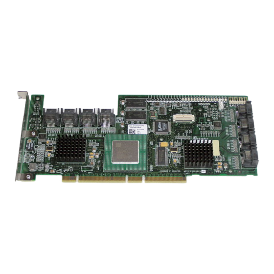
Four Serial ATA interface cables Technical Support ID (TSID) label (See Adaptec 2410SA Controller The Adaptec 2410SA controller is shown below. Note the position of the Serial ATA interface connectors necessary for attaching the Serial ATA hard drives. Serial ATA Connectors... -
Page 16: Raid
Adaptec Serial ATA RAID 2410SA Quick Installation Guide—This printed guide contains the essential information for installing the controller in most situations. Adaptec Serial ATA RAID 2410SA Installation and User’s Guide (this guide) Adaptec Serial ATA RAID 2410SA Command Line Interface Software Reference Guide—Provides detailed descriptions of the... -
Page 17: Simple Volume
Controller Features The Adaptec 2410SA controller supports four Serial ATA drives. The controller offers the features and performance ideal for high- end workstations and entry-level servers. Conforms with PCI Local Bus Specification, Revision 2.2 64-bit, 66-MHz PCI interface compatible with 32-bit/33-MHz... -
Page 18: Array Migration
RAID 0 RAID 1 RAID 5 RAID 10 To modify an array, refer to the Adaptec Storage Manager-Browser Edition online Help. Windows supports Online Capacity Expansion (OCE). That is, on completion of an array expansion, the additional capacity can be used without restarting the system. -
Page 19: Automatic Failover
The Adaptec 2410SA controller supports two types of hot spares: Global—Protects every array that the drive has enough available capacity to protect. Dedicated—Protects only the array that it has been assigned to protect. Automatic Failover This feature allows the controller to automatically rebuild an array when a failed drive is replaced with a new drive. -
Page 20: Storage Management Software Overview
Storage Management Software Overview The Adaptec 2410SA controller includes the following software tools to manage your storage subsystem: Adaptec Storage Manager – Browser Edition—Browser-based storage management software that provides all of the creation, management, and data logging needed to manage arrays. -
Page 21: Safety Information
Safety Information To ensure you personal safety, as well as the safety of you equipment: Keep your work area and the computer clean and clear of debris. Before opening the system cabinet, unplug the power cord. Notes and Cautions This Installation and User’s Guide uses notes and cautions that emphasize important information, as described below: Note: Emphasizes important information that, if ignored, would not result in injury, property damage, or data loss. - Page 22 When you need to put your controller down, use an antistatic surface such as the bag supplied in your kit. If you plan to return the controller to Adaptec, put it back in its antistatic bag immediately. Introduction...
-
Page 23: Installing The Controller
Installing the Controller In this Chapter... Overview Installing the Controller Checking Your Controller and Devices Determining the Boot Controller Overview To install the controller and drives, all you need is up to four of each of the following: Serial ATA hard disk drives Serial ATA cables (supplied in this kit) Configuration of Serial ATA devices is simple for the following reasons:... - Page 24 Installing the Controller To install the controller in the system cabinet: 1 Shut down your computer and disconnect the power cord. 2 Open the computer cabinet and identify an unused PCI slot. 3 If your computer accepts low-profile brackets only, install the low-profile bracket supplied with your kit in place of the standard full-height bracket.
-
Page 25: Checking Your Controller And Devices
To add a second bootable controller, you may need to enter Setup and change the hard disk boot sequence so that the Adaptec 2410SA controller heads the list. If Setup does not allow this change, your system BIOS may not be configurable to allow the Adaptec 2410SA controller to act as a second boot device. -
Page 26: Installing The Driver
Existing system—The computer has an operating system and the Adaptec 2410SA is being installed as a secondary controller. Adaptec recommends the following driver installation workflow: 1 Create a driver disk. See details. -
Page 27: Creating The Driver Disk
1 Set your system BIOS so that your computer boots from the CD-ROM drive. 2 Insert the Adaptec installation CD and turn on the computer. 3 Follow instructions and respond to prompts as necessary to get to the Adaptec Start Menu. -
Page 28: Windows
Press S to specify that the driver is on the floppy disk, and then press Enter. The computer reads the disk. 6 When the Adaptec driver is found, press Enter. Follow the on-screen instructions, responding as needed to complete the installation. -
Page 29: Adding The Driver To An Existing System
Adding the Driver to an Existing System In this scenario, you are adding the driver to an existing Windows system. To install the driver: 1 Install and configure the controller and hard disk drives according to the instructions in 2 Start Windows. Windows launches the Found New Hardware Wizard, which searches for the controller driver. -
Page 30: Linux
SuSE Linux only—The controller is not supported as a bootable controller. In other words, you can only add the driver to an existing system. For the most up-to-date information on Adaptec’s support of Linux, visit www.adaptec.com Installing the Driver in a New Red Hat System In this scenario, you are installing the controller in a new Red Hat 7.3 or 8.0 Linux system. -
Page 31: Adding The Driver To An Existing System
6 When prompted, insert the driver disk and then select OK. 7 Follow the prompts to set up your preferred environment. 8 If you intend to install other third-party devices, proceed with the installation of those devices. Otherwise, select Done. 9 Proceed with the Linux installation according to the Red Hat instructions. -
Page 32: Unixware And Openunix
UnixWare and OpenUNIX Although the driver disk you create for UnixWare 7.1.1 and OpenUNIX 8 differ, the installation procedures for these operating systems are the same. Installing the Driver on a New System In this scenario, you are installing the controller in a new UnixWare 7.1.1 or OpenUNIX 8 system. -
Page 33: Installing Adaptec Storage Manager - Browser Edition
Installing Adaptec Storage Manager on Linux Installing Adaptec Storage Manager on UNIX Overview This chapter discusses the installation procedure for installing Adaptec Storage Manager – Browser Edition to enable remote and local management of arrays. For instructions on using this application, see Chapter... -
Page 34: Supported Browsers
On Linux Adaptec-supplied and installed version of Mozilla Netscape 7 or later When using Adaptec Storage Manager, you need to log on to your system with administrator privileges. Typical, Custom, and Compact Installations You can select from the following setup options: Typical (default)—Supports local and remote management;... -
Page 35: Remote And Managed Systems
The remote system does not necessarily contain a RAID controller; however, it must contain, at minimum, the Adaptec Web Server and a browser (either Internet Explorer or Netscape). The managed systems contain RAID controllers and arrays, and at least the Managed System Components. -
Page 36: Installing Adaptec Storage Manager On Windows
To install Adaptec Storage Manager – Browser Edition: 1 Verify that a supported browser is installed. See Browsers on page 4-2 2 Insert the Adaptec installation CD and wait for the executable to start the installation. If this does not occur, browse the CD and click Autorun. -
Page 37: Configuring Internet Browsers On Windows
If you are managing a local storage array and your computer uses a proxy server, you need to configure your browser to enable Adaptec Storage Manager to bypass the proxy server. Also, if you are managing remote systems, you need to configure Adaptec Storage Manager to bypass the proxy server when communicating with these systems. - Page 38 Privacy tab. There is no setting for blocking Intranet cookies. If you are using a proxy server to access the Internet, you must bypass the proxy server to access the Adaptec Storage Manager Web server. To verify whether you are using a proxy server: 1 From Internet Option window, click the Connections tab.
- Page 39 If you know the IP address of the managed system you want to manage remotely: 1 Select Edit > Preferences > Advanced > Proxies > Manual proxy configuration > No Proxy For 2 Type the managed system’s IP address. Installing Adaptec Storage Manager – Browser Edition Chapter 5, Using Adaptec Edition.
-
Page 40: Installing Adaptec Storage Manager On Linux
Installing Adaptec Storage Manager on Linux Note: When performing this installation, keep in mind that Linux is case sensitive. To install Adaptec Storage Manager on a Linux computer and configure the desired Internet browser: 1 Insert the Adaptec installation CD. -
Page 41: Installing Adaptec Storage Manager On Unix
10 Remove the Adaptec installation CD. Your computer must have a Web browser supporting JavaScript and cookies. To use Adaptec Storage Manager, you need to log on to your computer with root privileges. Installing Adaptec Storage Manager on UNIX Your UNIX system may only be used as a managed system. -
Page 42: Using Adaptec Storage Manager - Browser Edition
Using Adaptec Storage Manager – Browser Edition In this Chapter... Overview Architecture Overview Logging In Installing a Security Certificate Registering Your Software The Basics... -
Page 43: Overview
Overview This chapter describes how to use Adaptec Storage Manager – Browser Edition to manage arrays. Once you are logged in, you will find convenient online help to guide you through the details of creating, configuring, and managing arrays. Note: Your controller may not support all of the features described. -
Page 44: Architecture Overview
A locally managed system requires all of the following components: A supported Web browser, which should already be installed on the system. The Adaptec Web service which supplies content displayed on the Web browser. An Adaptec-supplied storage agent. A remotely managed system requires all of the following components: The remote system must contain a browser. -
Page 45: Logging In
In Windows, click Start > Programs > Adaptec Storage Manager > Adaptec Storage Manager – Browser Edition. In Linux, click Start > System > Adaptec Storage Manager. The Login screen, shown below, is presented. 2 Enter the host name or IP address of the system you want to manage and the username and password you would use to log into that system. - Page 46 When connection to the remote system is established, the System Login screen appears. Note: If you are using a proxy server to access the Internet, you must bypass the proxy server to access the Adaptec Storage Manager Web server. See Browsers on Windows on page 4-5...
-
Page 47: Installing A Security Certificate
Installing a Security Certificate If you chose not to install a security certificate when you installed Adaptec Storage Manager – Browser Edition, you must install the certificate when you run the application for the first time. To create the certificate: 1 When the Security Alert window appears, click View Certificate. -
Page 48: The Basics
The Basics An example of a typical Adaptec Storage Manager – Browser Edition screen is shown below. Note: Depending on your operating system, browser, and color scheme you may notice some differences between this illustration and your screen. The header frame, at the top of the screen, contains the name of the system that you are currently connected to and a number of buttons that perform various actions or open additional windows. -
Page 49: Pop-Up Tool Tips
Using Adaptec Storage Manager – Browser Edition Immediately following the header frame is a controller information line including the model number of the first Adaptec RAID controller found in the system and the amount of cache memory (if any) installed on that controller. - Page 50 The selected display mode button will appear in a lighter shade of blue than the other two buttons. The default display is the Text Description View, but in the condensed view used when Adaptec Storage Manager is loaded, the display is the same in all three modes.
-
Page 51: Logical Devices
By rounding drive capacities downward, this possibility is effectively eliminated. Logical Devices As described earlier, when Adaptec Storage Manager loads, the Logical Devices view is expanded and you can see the arrays present on the controller. - Page 52 Logical Devices view. The Events, Properties, and Tasks buttons in the header frame. Selecting any of these three buttons displays a new window with additional information and options specific to that array. Using Adaptec Storage Manager – Browser Edition 5-11...
-
Page 53: Adaptec Raid Configuration Utility
Using SATASelect Using the Disk Utilities Viewing the Event Log The Adaptec RAID Configuration (ARC) utility is an embedded BIOS utility that includes: Array Configuration Utility (ACU)—Used to create, configure, and manage arrays. Also used to initialize and rescan drives. -
Page 54: Using The Array Configuration Utility
The Adaptec RAID Controller menu appears, presenting the following options: Array Configuration Utility SATASelect Utility Disk Utilities To select an option from this menu, or from any of the menus within ARC, browse with the arrow keys and then press Enter. In some cases, selecting an option displays another menu. - Page 55 3 From the ACU menu, select Manage Arrays. 4 Select the array you want to make bootable and then press Ctrl+B. This changes the selected array’s number to 00, making it the controller’s boot array. 5 Restart the system. Adaptec RAID Configuration Utility...
- Page 56 4 Select the array you wish to delete and then press Delete. 5 In the Array Properties dialog box, press Delete again and then press Enter. the following message is displayed: Warning!! Deleting will erase all data from the array. Do you still want to continue? (Yes/No): Adaptec RAID Configuration Utility...
- Page 57 Select Hotspares drives list. 4 Press Enter to save the removed hot spare drive assignment. the following message is displayed: Have you finished managing Hotspare drives? 5 Press Y (for yes) to return to the Main menu. Adaptec RAID Configuration Utility...
-
Page 58: Creating Arrays
ARC utility. Otherwise, the array configuration may be erased. If necessary, enter the ARC utility. Upon entering ARC, accept the configuration that ARC reports, and then modify the configuration to suit your needs. Adaptec RAID Configuration Utility... - Page 59 Assigning Array Properties The ACU can be used to assign array properties only prior to array creation. (After the array is created, you need to use Adaptec Storage Manager.) To assign properties to the new array: 1 In the Array Properties menu, select an array type and then press Enter.
-
Page 60: Initializing Disk Drives
6 Repeat step 5 until all the drives to be initialized are selected. 7 Press Enter. 8 Read the warning message, ensure that you have selected the correct disk drives to initialize, and then press Y to continue. Adaptec RAID Configuration Utility Viewing Array Properties on page A-3... -
Page 61: Rescanning Disk Drives
1 When you turn on or restart your system, press Ctrl+A to access the ARC utility when you see the following message: Press <Ctrl><A> for Adaptec RAID Configuration Utility 2 If multiple controllers are installed, select the controller you want to configure and then press Enter. - Page 62 (less than with controller cache) of data loss or corruption during a power failure. Runtime BIOS (Default: Enabled)—When Enabled, the Adaptec 2410SA controller BIOS allows the controller to act as a bootable device. Disabling the BIOS allows another suitable controller to act as the boot device.
-
Page 63: Using The Disk Utilities
2 If multiple controllers are installed, select the controller you want to configure and then press Enter. 3 From the ARC menu, select Disk Utilities. 4 Select the desired disk and then press Enter. You are offered the following options: Adaptec RAID Configuration Utility A-11... -
Page 64: Viewing The Event Log
1 When you turn on or restart your system, press Ctrl+A to access the ARC when prompted by the following message: Press <Ctrl><A> for Adaptec RAID Configuration Utility 2 If multiple controllers are installed, select the controller you want to configure and then press Enter. -
Page 65: Dos Utilities
The Adaptec Flash Utility (AFU) is a DOS application used to update the flash EEPROM components on one or more Adaptec SCSI RAID controllers. The utility can also be used to verify a controller’s current flash contents against the flash images in a specified file or to save a controller’s current flash contents to a file. -
Page 66: Overview Of The Afu
The process of updating a controller’s flash must be done carefully to avoid rendering the controller inoperable. AFU is designed to be easy to use with all the necessary safeguards to prevent a user from accidentally damaging the controller’s flash contents. Overview of the AFU The AFU performs the following primary functions: Update—Updates all the flash components on a controller with... -
Page 67: Firmware Floppy Disk Kit
The flash image may be comprised of multiple UFI files. To create a controller firmware kit on floppy disks: 1 Locate the necessary files on the Adaptec installation CD at: packages/firmware/adp where xxx is the model number of your controller. -
Page 68: Running The Afu
Running the AFU You can run the AFU from its graphical user interface (GUI) or from the command line. Accessing the AFU from the GUI To access the AFU: 1 At the DOS command prompt (typically arguments. The main menu to the AFU is displayed. 2 Select Select Controllers and select the controllers to be flashed. -
Page 69: Flashing The Firmware Using Afu
The AFU switches are as follows /C <Controller ID> is one or more controller IDs representing the set of controllers on which to perform the specified command. You can specify a single controller ID, for example: /C 0 multiple IDs separated by commas, for example: /C 0,2 or ALL to indicate all controllers. - Page 70 5 At the DOS prompt, type afu list and press Enter. This command displays a list of the controllers in your system. Take note of the controllers you would like to update and its number (or numbers if there are more than one). Verify that the controller you wish to update is identified.
-
Page 71: Afu Commands
You do not have to restart the computer upon completion of this command. Options None Default Switch Values None Example A:\> AFU LIST Adaptec Flash Utility V4.0-0 B5749 (c)Adaptec Inc. 1999–2002. All Rights Reserved. Controllers Detected and Recognized: Controller #0 (03:05:00) Adaptec 2410 DOS Utilities... - Page 72 SAVE The SAVE command saves the contents of a controller’s flash in a UFI file. The name of the UFI file is based on the controller type and cannot be changed. Use the /D switch to specify the drive and directory where you want AFU to create the UFI file. Note: You can specify only one controller ID.
- Page 73 (c)Adaptec Inc. 1999–2002. All Rights Reserved. Updating Controller 0 (Adaptec 2410) Reading flash image file (Build 5749) AFU is about to update firmware on controllers Adaptec 2410 ***PLEASE DO NOT REBOOT THE SYSTEM DURING THE UPDATE*** This might take a few minutes.
-
Page 74: Afu Error Handling
A:\> AFU VERSION /C 0 Adaptec Flash Utility V4.0-0 B5749 (c)Adaptec Inc. 1999–2002. All Rights Reserved. Version Information for Controller #0 (Adaptec 2410) ROM: Build 5748 [VALID] Fri Sep 27 13:28:40 EDT 2002 A:\> AFU VERSION /C ALL AFU Error Handling Because the AFU can run without user interaction, it exits immediately whenever an error is detected. -
Page 75: Using The Array Configuration Utility (Acu
Using the Array Configuration Utility (ACU) Adaptec RAID Configuration (ARC) is a embedded BIOS utility that includes: SATASelect—Used for changing device and controller settings, Disk Utilities—Used for low-level formatting or verifying disk media, and for performing other functions. Array Configuration Utility (ACU)—Used for creating, configuring, and managing arrays. -
Page 76: Running The Acu
If you need to initialize a device, see To create an array, select the drive or drives to be used in the array and then assign the desired properties to the array. on the Adaptec installation CD. page B-16. DOS Utilities... - Page 77 Selecting Segments for New Arrays To select one or more segments to assign as members of the new array: 1 Use the arrow keys to select a channel. 2 Use the arrow keys to select the drives to assign to the new array and press Insert.
- Page 78 2 Type in an optional label for the array and press Enter. 3 Enter the desired array size. The maximum array size available based on the segments you selected is displayed automatically. If you want to designate a different array size, type the desired array size and select MB (megabytes), GB (gigabytes), or TB (terabytes) from the drop-down list.
-
Page 79: Managing Arrays
Managing Arrays The Manage Arrays option enables you to perform the following functions: Viewing Array Properties Assigning Hot Spares Removing Hot Spare Drives Initializing a Hard Drive Making an Array Bootablee Deleting Arrays These operations are described in greater detail in the sections that follow. - Page 80 3 Select a drive and press the Insert key to assign the drive as a spare. The specified drive is displayed in the Assigned Hotspares Drives list. 4 Press Enter to save the spare drive assignment. The following prompt is displayed: Have you finished managing Hotspare drives? 5 Press Y (for yes) to return to the Main menu.
- Page 81 To initialize a drive: 1 Select Initialize Drives from the Main menu. 2 Use the arrow keys to select a channel. 3 Select the disks you want to initialize and press Insert. 4 Press Enter. 5 Read the warning message and ensure that you have selected the correct devices to initialize.
-
Page 82: Using The Scripting Features
Deleting Arrays Caution: Back up the data on an array before you delete it. All data on the array is lost when you delete the array, and you cannot restore a deleted array. To delete an existing array: 1 Select Manage Arrays from the Main menu. 2 Select the array you want to delete and press Delete. - Page 83 The table below lists the required and optional ACU command-line switches. Switch Description Playback Mode Switch—In this mode, the ACU reads /P <file> the contents of the specified script file and creates arrays and configures channel settings based on the properties defined in the script.
- Page 84 Playback Mode Playback mode enables you to create one or more arrays based on the properties defined in a script file. It also enables you to configure certain properties for each channel on the controller. When you create an array, you can specify any of the array properties listed in the table below.
- Page 85 In addition, there are other array properties that enable you to control the various array settings during creation. See Definition Block Properties on page B-25 properties. Note: You can configure each individual channel on the controller using this property, which specifies the device ID number of the controller on the channel.
- Page 86 Because the ACU reads the entire script file before creating any arrays, the position of the InitializeAll=Yes property within the script is not significant. Continuing the previous example, if InitializeAll=Yes is specified in the second RAID 5’s definition, the ACU initializes all drives before creating the first RAID 0. Note: If a build/verify is in progress when an array is deleted, it is automatically terminated.
- Page 87 The ACU provides a way to do this. When you use record mode to record a controller’s configuration and you specify a log file (/L switch), the ACU writes build/verify and clear status information about each array in the configuration to the log file. An application or batch file can then parse the resulting log file to determine whether an array’s build/verify or clear is complete, in progress (a percentage of the task completed), or failed.
-
Page 88: Script File Syntax
Build/Verify Operations on RAID 10 Arrays For a RAID 10 array, the status message indicates the percent of the build/verify completed for the parent and child tasks. The status updates to OK when the tasks are complete. A sample RAID 10 build status is as follows: Array #1 Status : BUILD/VERIFY = 30% Script File Syntax... -
Page 89: Array Definition Block Properties
Array Definition Block Properties The table below lists the properties that can be specified within an array definition block. The table lists each property’s keyword, whether it is required, and its default value (if any). Note that the keywords are arranged so the required keywords are listed first. Required Keyword Array... - Page 90 Required Keyword Wait WaitForBuild WriteCache The following sections describe each of these keywords in detail. Array Keyword Array is a required keyword, indicating the start of an array definition block. It accepts an optional array label value. Examples Array Array=MyData Drives Keyword Drives is a required keyword, specifying the devices to use in creating the array.
- Page 91 Type Keyword Type is a required keyword, indicating the array type. There is no default value. Note: For information about the maximum number of drives supported and minimum number of drives required, see page B-14. The Type keyword values are: Volume RAID0 RAID1...
- Page 92 Notes When assigning spare drives to a RAID 10 array, the ACU assigns all the drives in the list to all the arrays within the multilevel array. ACU only creates dedicated hot spares. If the same drive is assigned to protect multiple arrays, only the last array that drive is assigned to is protected.
- Page 93 Examples InitializeAll=Yes InitializeAll=No Method Keyword Method is an optional keyword, indicating which method to use when creating a RAID 5 array. Possible values are: Build (the default)—Build/verify the array. Clear—Clear the array. Quick Init - Make the array available immediately Overall, the Build method takes longer than Clear, but it enables you to begin using the array immediately.
- Page 94 Size Keyword The Size keyword specifies the size of the array. Specify the size as an integer or a decimal number, followed by the unit keyword MB (megabytes), GB (gigabytes), or TB (terabytes). A unit keyword is required with a numeric size value. If no unit keyword is specified, the ACU exits with an error.
- Page 95 Wait Keyword The Wait keyword indicates whether the ACU should wait for the new array’s build/verify or clear to complete before continuing. The Wait property is optional; if not specified, the ACU waits for the array’s build/verify or clear to complete before continuing. Specify Wait=No to allow the ACU to continue while the build/ verify or clear completes in the background.
-
Page 96: Error Handling
Error Handling Because the ACU scripting feature is designed to run without user interaction, the ACU handles errors during record and playback by simply exiting immediately whenever an error is detected. Whenever the ACU encounters an error during record or playback—for example, an unrecognized keyword in a script file—... - Page 97 Code Description Specified array size too big—You specified an array size that is larger than the maximum size allowed for this array. Number of drives do not match the array type—The number of drives you selected is invalid for the type of array specified. Unable to initialize drive—The ACU was unable to initialize one or more devices.
-
Page 98: Playback And Record Notes
Playback and Record Notes When using ACU in playback or record mode, note the following: When recording an array, the ACU does not create a Wait keyword within an array’s definition block in a script file. When playing back any script file generated from the ACU record option, the ACU uses the default setting Wait=Yes when creating an array unless you first edit the script file and include a Wait=No line in the array’s definition block. - Page 99 The following sample script file is a sample RAID.ACU script as referred to in the previous ACU command. This script creates the following arrays—a 500 MB, single-disk volume and a 2-GB, two- drive RAID 1 with a hotspare. # Script to create volume, mirror, and RAID 5 arrays # Create a 500MB volume labeled ‘MySystem’...
-
Page 100: Command Line Interface (Cli)
This Command Line Interface (CLI) enables you to configure and manage controller components. The CLI contains most of the functionality offered by Adaptec Storage Manager – Browser Edition and some additional functionality not offered by Adaptec Storage Manager. C-15 C-16... -
Page 101: Terminology
CLI commands enable you to automate testing or array creation in a production environment using Windows command scripts and Linux and UNIX shell scripts. This appendix describes briefly some of the commands available in the CLI. For a full description of all the CLI commands, refer to the CLI Software Reference Guide. -
Page 102: Accessing The Cli In Ms-Dos
1 Click the Start button. 2 Click Programs. 3 Browse to SMBE. The Adaptec program group displays. 4 Click CLI. Note: In Windows, when the CLI executes an background command, it displays status information in the title bar of a DOS command prompt window. -
Page 103: Opening And Closing A Controller
Opening and Closing a Controller To prepare a controller to receive a CLI command, you first need to open the controller. You may open only one controller at any time. To open controller AAC0 commands, type: CLI> open AAC0 The prompt changes to reflect the open controller, as shown in the next example. - Page 104 Displaying Information about Your Disks Before creating any array, use the disk show space command to display information about your disks. Note: Before you can create arrays, you need to initialize the member drives. In the following example, the Usage column indicates Free for each disk, which means that the space on each disk consists of available space.
- Page 105 Creating a RAID 0 When creating a RAID 0, you need to determine the stripe size that is most suitable for your environment. The stripe size attribute indicates the number of bytes in a stripe, the amount of data written to a segment before the I/O data stream switches to the next segment in the array.
-
Page 106: Managing Failover Options And Hot Spares
The stripe size can be 16, 32, or 64 KB. The default stripe size is 64 KB. Note that you can use the container reconfigure command at a later time to change the stripe size. To create a RAID 5, use the container create raid5 command. In the following example, a RAID 5 is created on devices 0:01:0, 0:02:0, and 0:03:0 using 100 MB of available space from each device. - Page 107 Alternatively, you can use the automatic failover commands that enable you to remove a failed drive and add a hot spare in its place. The controller automatically assigns the new hot spare to replace the failed drive without your having to first assign it using the container set failover or container set global_failover commands.
-
Page 108: Displaying Controller Information
Example of controller list: CLI> controller list Executing: controller list Adapter Name Adapter Type ------------ ------------ \\.\AAC0 Adaptec xxxxx controller details Controller Attribute controller (adapter) name controller (adapter) type controller availability controller remote computer controller serial number controller CPU type... - Page 109 AAC0> controller details Executing: controller details Controller Information ---------------------- Remote Computer: . Device Name: AAC0 Controller Type: Adaptec xxxxxx Access Mode: READ-WRITE Controller Serial Number: Last Six Digits = 8A277A Number of Buses: 2 Devices per Bus: 15 Controller CPU: i960...
-
Page 110: Displaying Disk Information
Displaying Disk Information The CLI enables you to monitor or manage disk attributes, prepare a disk for use by a controller, and detect defects using the following CLI commands: disk list Disk Attribute device ID device type removable media vendor ID product ID revision number number of blocks... -
Page 111: Displaying Array Information
Example of disk show defects: AAC0> disk show defects /full=true (0,1,0) Executing: disk show defects /full=TRUE (CHANNEL=0,ID=1,LUN=0) Number of PRIMARY defects on drive: 5 Defect 1 at cylinder 229, head 7, sector 203 Defect 2 at cylinder 575, head 0, sector 219 Defect 3 at cylinder 576, head 0, sector 55 Defect 4 at cylinder 578, head 0, sector 238 Defect 5 at cylinder 579, head 0, sector 74... - Page 112 Array Attribute stripe size read only read/write lock resident file system multi-partition container That a file system resides on a multipartition UNIX opened unknown file system unmapped containers phantom container valid container mirror set create mirror set normal reconfiguration copy container reconfiguration destination container...
- Page 113 Example of container list: AAC0> container list Executing: container list Total Oth Stripe Label Type Size Ctr Size ----- ----- ----- --- ------ ------- ----- ------------ Volume 30MB Venus container show cache Cache Attribute global container read cache size global container write cache size read cache setting Example of container show cache:...
-
Page 114: Cli Command Dictionary
CLI Command Dictionary This section contains a command reference. General Control Commands close Closes the currently opened controller. exit Closes the opened controller and exits the CLI. help [/full] [{command}] Invokes general or topical help. Parameters {command}—If a command has more subcommands, help lists the subcommands and their functions. -
Page 115: Container (Array) Commands
open [/readonly={boolean}] [/domain={string}] {string} Opens a controller for access by the CLI. The controller must be open before any command can be targeted at that controller. Parameters {string}—Computer name and the controller to open. Switches /readonly—If TRUE, the controller is opened for read-only access. - Page 116 Switches /always—Specifies whether to clear the array even if it has data on it. The default is FALSE, meaning that the command clears the array only if it has no data on it. All user files must be closed; the /always switch cannot override this restriction. /wait—...
- Page 117 Switches /io_delay—Number of milliseconds between each I/O used for the RAID 1 create. /wait— If FALSE (the default), the operation is performed in the background and the command prompt is returned immediately. If TRUE, the operation is performed immediately and the command prompt is returned only when done.
- Page 118 container create raid5 [/cache={boolean}] [/stripe_size={integer}] [/clear={boolean}] [/label={string}] [</quick_init={boolean}>] [/scrub={boolean}] [/wait={boolean}] {free_space} [{device_ID}...] Creates a RAID 5. Parameters {free_space}—Device and its associated available space used to create the array. {device_ID}—One or more devices whose available space to use to create the array. Switches /cache—Specifies whether to enable the array’s cache.
- Page 119 Switches /cache—Specifies whether to enable caching on the array. /stripe_size—Stripe size for the RAID 0. The default is 64 KB. /label—Label to assign to the new RAID 0. container create volume [/cache={boolean}] [/label={string}] {device_ID}, {free_space}, {device_ID}, [{free_space}...] Creates a volume. Parameters {device_ID}—Device and its associated available space to use to create the volume.
- Page 120 Parameters {container}—ID of the array containing information to display. Switches /all—Specifies whether to list all containers on the system. /full—Specifies whether to display detailed information. container move {container1} {container2} Moves the first array number specified to the second array number specified; in effect, to renumber an array. Parameters {container1}—ID of the array to renumber.
- Page 121 container reconfigure [/stripe_size={integer}] [/mirror={boolean}] [/partition_move={boolean}] [/partition_size={integer}] [/raid5={boolean}] [/raid10={boolean}] [/restart={boolean}] [/stripe={boolean}] [/volume={boolean}] [/wait={boolean}] {container} [{device_ID}...] Changes the configuration of an array. Parameters {container}—ID number of the array to reconfigure. {device_ID}—One or more devices. Switches /stripe_size—Stripe size of the array. /mirror—Reconfigure the array as a RAID 1. /partition_move—Specifies that the array will move partitions instead of add extra space.
- Page 122 container remove global_failover {device_ID} [{device_ID}...] Removes a global failover assignment. Parameters {device_ID}—ID for the device to remove as a failover disk. container restore RAID5 {container} Tries to restore a RAID 5 that has a number of dead segments as members. Parameters {container}—ID of the RAID 5 to restore.
- Page 123 Switches /read_cache_enable—Specifies whether to enable the read- ahead cache. /unprotected—Specifies whether to set the container's NVRAM write-back cache to disable, enable when protected, or enable always. Use this switch in conjunction with the /write_cache_enable switch. /write_cache_enable—Specifies whether to set the container's NVRAM write-back cache to disable, enable when protected, or enable always.
-
Page 124: Controller Commands
container set label {container} {string} Assigns a new label to the array. Parameters {container}—ID of the array to which to assign a label. {string}—Specifies the label to assign. container show cache {container} Displays caching parameters for an array. Parameters {container}—ID of the array whose associated cache parameters to display. - Page 125 controller firmware compare [/C{controller}] [{controller}...] [/D{UFI_file_path}] Compares the contents of each of the flash components on a controller to the corresponding image in User Flash Image (UFI) files and indicates whether they match. Switches /C{controller}—ID representing the set of controllers on which to perform the firmware comparison.
- Page 126 Switches /domain (Windows only)—Specifies the domain in which the host to be searched resides. controller pause_io [{integer}] Windows only—Pauses all I/O activity on the open controller to allow online manipulation of hardware. Parameters {integer}—Time in seconds to cause the controller to wait before resuming I/O.
-
Page 127: Disk Commands
controller set container_verify [/verify_enabled={boolean}] Turns the container verify task on or off. Switches /verify_enabled Specifies whether to turn on or off the container verify feature. The command defaults to TRUE, which means the command turns on the container verify feature. controller show automatic_failover Displays the automatic failover status (enabled or disabled) for the controller. - Page 128 disk initialize [/always={boolean}] [/unconditional={boolean}] {device_ID} Initializes a disk on the currently opened controller. Parameters {device_ID}—ID of the device to initialize, Switches /always—Specifies whether to initialize the disk even if the disk has existing data. (Cannot override open files.) Default is FALSE.
- Page 129 disk set smart [/all={boolean}] [/clear={boolean}] [/enable_exceptions={boolean}][/logerr={boolean}] [/perf={boolean}] [/report_count={boolean}] [{device_ID}] Changes a disk’s Self-Monitoring, Analysis and Reporting Technology (SMART) configuration configuration. Parameters {device_ID}—ID of the device on which to change SMART configurations. Switches /all—Specifies whether to enable SMART configurations for all disks. /clear—Clears the SMART error counts for the disk.
- Page 130 disk show partition Displays a list of partitions on the disks attached to the currently opened controller. disk show smart [/all={boolean}] [/full={boolean}] [/view_changeable={boolean}] {device_ID} Displays drive Self-Monitoring, Analysis and Reporting Technology (SMART) configuration information for one or all disks. Parameters {device_ID}—ID of the device for which to display SMART information.
-
Page 131: Logfile Commands
Switches /repair—If FALSE (the default), the command only reports failures. If TRUE, bad blocks are automatically repaired, if possible. /wait— If FALSE (the default), the operation is performed in the background and the command prompt is returned immediately. If TRUE, the operation is performed immediately and the command prompt is returned only when done. -
Page 132: Task Commands
Task Commands Use the CLI commands to display and manage tasks. A task is an operation that occurs only on the controller, asynchronous to all other operations. Examples of tasks are clearing a disk and creating a RAID 1. Once a task is running on the controller, the CLI enables you to display, stop, suspend, and resume the task. -
Page 133: Enclosure Commands
Enclosure Commands The enclosure commands operate on enclosure management devices that support Version 1.0 of the SAF-TE specification. If you are not using an enclosure, the following commands will not be available. enclosure activate slot {enclosure} {slot} Activates a device in a slot in the SAF-TE enclosure. Parameters {enclosure}—ID associated with the enclosure management device on which to activate a device. - Page 134 enclosure prepare slot {enclosure} {slot} Prepares a device in a slot for insertion/removal. Parameters {enclosure}—ID associated with the enclosure management device on which to prepare a slot. {slot}—Unit number associated with the slot. enclosure set alarm [/on={boolean}] {enclosure} Turns the audible alarm on or off. Parameters {enclosure}—ID associated with the enclosure management device whose audible alarm to set.
- Page 135 enclosure set power [/off{=boolean}] {enclosure} {powersupply} Turns on or off a specific power supply. Parameters {enclosure}—ID associated with the enclosure management device. {powersupply}—Unit number associated with the power supply. Switches /off—Specifies whether to turn on or off the power supply associated with the unit number.
- Page 136 enclosure show power [{enclosure}] [{powersupply}] Displays the status of one or more power supplies. Parameters {enclosure}—ID associated with the enclosure management device for which to display power supply status. {powersupply}—Unit number associated with the power supply. enclosure show slot [{enclosure}] [{slot}] Displays the status of a specific device slot on a specific enclosure.
-
Page 137: Using Automated Command Scripts
Using Automated Command Scripts To execute a CLI command script, type the at sign (@) followed by the file name that contains the CLI commands, for example: AAC0>@commandscript.txt In its simplest form, a CLI command script is a text file that contains valid CLI commands. -
Page 138: Spanned Volume
Otherwise, the RAID tends to be limited in capacity and performance to that of the smallest and slowest drive. The Adaptec 2410SA controller supports up to four drives and supports RAID levels 0, 1, 5, 10, spanned volume, and simple volume. -
Page 139: Raid 0
RAID 0 A RAID 0 is created by striping data across two or more disk drives. This striping scheme creates no redundancy to protect the data. However, because the drives share load equally, RAID 0 provides the best read and write performance of any RAID type. An example of a RAID 0 array is shown below. - Page 140 RAID 5 This RAID type requires at least three drives. Like RAID 0, data is striped across the drives. However, in RAID 5, parity is stored separately from data, and occupies the equivalent of one drive. The controller generates parity every time data is written to the array, and it is distributed in stripes across all the drives.
-
Page 141: Simple Volume
RAID 10 This dual-level RAID type is created by using two or more equal- sized RAID 1 arrays to create a RAID 0. Both read and write performance are improved due to array striping. However, the performance improvement costs additional storage space due to the mirroring of the arrays. -
Page 142: Specifications
Specifications DC Power Requirements Voltage Ripple and noise Current Requirements Adaptec 2410SA Environmental Specifications Ambient temperature Relative humidity Altitude Note: Forced airflow is recommended, but not required. 5 V ± 10% 50 mV peak-to-peak maximum 1 A maximum 0 °C to 50 ° C... -
Page 143: Glossary
Glossary activity See task. Array Configuration Utility. An application used to create, configure, and manage arrays from the controller’s BIOS or MS-DOS. array A logical disk created from available space and made up of one or more segments on one or more physical disks. Arrays are typically used to provide data redundancy or enhanced I/O performance. - Page 144 Glossary bad segment Segment that is in an unknown state. background consistency check Consistency check performed as a background process. See also consistency check command. bootable array Array configured as the boot device. build Background initialization of a redundant array. The array is accessible throughout.
- Page 145 Glossary clear Foreground initialization of a fault-tolerant array. A clear operation zeros all blocks of the array. The array is not accessible until the clear task is complete. concatenation Joining of physical or logical drives in sequential order. consistency check command The controller continuously performs a verification on a redundant array to data integrity.
- Page 146 See also redundant. foreign disk Disk that has previously been initialized on another Adaptec RAID controller. The RAID signature on the disk allows the RAID controller to identify whether or not the disk was initialized on the controller it is currently connected to.
- Page 147 Glossary free space/segment available space/segment. hard disk, hard drive Basic unit of nonvolatile, nonremovable, magnetic storage media. See also disk drive. hot spare A hard drive, an array member, that is not used in day-to-day data storage but, instead, is reserved for use as a replacement for one of the other drives in the array in the event of a failure.
- Page 148 Glossary legacy disk Disk that contained a valid partition table when connected to the controller. The controller manages the disk as a legacy disk array where there is a one-to-one logical-to-physical mapping of array to disk. logical device Volume comprised of space from one or more physical drives and presented to the operating system as if it were a single storage unit.
- Page 149 Glossary partition See segment. phantom object Object that represents a component that cannot be configured by the controller management software; for example, a missing drive. quick init An array initialized using the Quick Init option is available immediately, with no on-going background controller activity. All data written to an array that has been quick initialized is protected.
- Page 150 Glossary drive. The controller generates parity every time data is written to the array, and it is distributed in stripes across all the drives. RAID 10 Dual-level RAID type created by using two or more equal-sized RAID 1 arrays to create a RAID 0. Both read and write performance are improved due to array striping.
- Page 151 Serial ATA (SATA) A successor to ATA that uses a serial, instead of parallel, interface. simple volume A volume made up of disk space from a single disk. It can consist of a single region on a disk or concatenated, multiple regions of the same disk.
- Page 152 verify consistency check command. volume simple volume, spanned volume. Glossary Glossary-10...
- Page 153 Adaptec, Inc. 691 South Milpitas Boulevard Milpitas, CA 95035 USA ©2003 Adaptec, Inc. All rights reserved. Adaptec and the Adaptec logo are trademarks of Adaptec, Inc. which may be registered in some jurisdictions. Part Number: 513602-06, Ver. AA MKL 05/03...
Need help?
Do you have a question about the RAID 21610SA and is the answer not in the manual?
Questions and answers