Table of Contents
Advertisement
Advertisement
Table of Contents

Related Manuals for Adaptec 3405


Summary of Contents for Adaptec 3405
- Page 1 Serial Attached SCSI RAID Controllers Installation and User’s Guide...
- Page 2 Copyright ©2010 Adaptec, Inc. All rights reserved. No part of this publication may be reproduced, stored in a retrieval system, or transmitted in any form or by any means, electronic, mechanical, photocopying, recording or otherwise, without the prior written consent of Adaptec, Inc., 691 South Milpitas Blvd., Milpitas, CA 95035.
- Page 3 Adaptec Customer Support If you have questions about installing or using your Adaptec product, check this document first—you will find answers to most of your questions. If you need further assistance, use the support options listed below. To expedite your service, have your computer in front of you.
- Page 4 Limited 3-Year Hardware Warranty 1. Adaptec, Inc. (“Adaptec”) warrants to the purchaser of this product that it will be free from defects in material and workmanship for a period of three (3) years from the date of purchase. If the product should become defective within the warranty period, Adaptec, at its option, will repair or replace the product, or refund the purchaser’s purchase price for the product, provided it is delivered at the...
- Page 5 (2) this device must accept any interference received, including interference that may cause undesired operation. Adaptec, Inc. Adaptec RAID 5085/Adaptec RAID 5405/Adaptec RAID 5445/ Adaptec RAID 5405Z/Adaptec RAID 5805Z/Adaptec RAID 5445Z/ Adaptec RAID 51245/Adaptec RAID 51645/Adaptec RAID 52445/...
-
Page 6: Table Of Contents
About the Adaptec RAID 5085... 20 About the Adaptec RAID 5405... 21 About the Adaptec RAID 5445... 22 About the Adaptec RAID 5805/5805Q ... 23 About the Adaptec RAID 51245... 24 About the Adaptec RAID 51645... 25 About the Adaptec RAID 52445... 26 About the Adaptec RAID 5405Z ... -
Page 7: Contents
Setting the Boot Controller ... 52 Creating an Array... 52 Creating an Array with the ACU ... 52 Creating an Array with Adaptec Storage Manager ... 54 Making Your Array Bootable ... 55 Installing the Driver and an Operating System Before You Begin... - Page 8 Managing Your Storage Space About Adaptec Storage Manager ... 68 Installing Adaptec Storage Manager ... 68 About the Adaptec RAID Controller Configuration Utility... 68 About the Adaptec RAID Configuration Utility ... 69 About the Adaptec Flash Utility ... 69 Which Utility Should I Use? ... 69 Solving Problems Troubleshooting Checklist ...
- Page 9 RAID 6 Arrays ... 89 RAID 60 Arrays ... 89 Selecting the Best RAID Level ... 90 Using the Adaptec RAID Configuration Utility Introduction to the ARC Utility... 92 Running the ARC Utility ... 92 Navigating the ARC Utility ... 92 Using the ACU to Create and Manage Arrays...
- Page 10 Adaptec RAID 52445 LED and I2C Connector Specification ... 132 Adaptec RAID 3085 LED Connector Specification... 135 Adaptec RAID 3405 LED and I2C Connector Specification ... 135 Adaptec RAID 3805 LED and I2C Connector Specification ... 137 Adaptec RAID 31205 LED and I2C Connector Specification ... 139 Adaptec RAID 31605 LED and I2C Connector Specification ...
-
Page 11: Contents
Technical Specifications Environmental Specifications... 152 DC Power Requirements ... 152 Current Requirements ... 152 Index Contents ●... -
Page 12: About This Guide
Terminology Used in this Guide... 13 How to Find More Information ... 13 This Installation and User’s Guide explains how to install your Adaptec also describes the utilities included in your controller kit, and provides a basic overview of Serial Attached SCSI (SAS) and Redundant Array of Independent Disk (RAID) technology. -
Page 13: What You Need To Know Before You Begin
Your RAID Controller on page Terminology Used in this Guide Because you can use your Adaptec RAID controller to manage data storage in a variety of configurations, the generic term “storage space” is used to refer to controller(s) and disk drives... -
Page 14: Kit Contents And System Requirements
Kit Contents and System Requirements In this chapter... Kit Contents... 15 System Requirements ... 15 This chapter lists the contents of your Adaptec RAID controller kit and the system requirements that must be met for you to successfully install and use your controller. -
Page 15: Kit Contents
Operating system support varies by controller type (3-series vs. 5- and 2-series). For up-to-date operating system version support check the readme on your RAID Controller Installation CD or visit the Adaptec Web Site at www.adaptec.com. From the main menu select Support>Knowledgebase>Find Answers. Select your controller type and OS support to generate a list of supported operating systems. - Page 16 Chapter 2: Kit Contents and System Requirements Available compatible PCIe slot (depending on your controller model—see the descriptions ● starting on page 20 MB of free disk drive space ● 16-bit SVGA color monitor with a resolution of at least 800 x 600 ●...
-
Page 17: About Your Raid Controller
About the Adaptec RAID 31605 ... 34 About the Adaptec RAID 2045 ... 35 About the Adaptec RAID 2405/2405Q... 36 About the Adaptec RAID 2805 ... 37 This chapter provides an overview of standard Adaptec RAID controller features, and describes the unique features of your controller. -
Page 18: Standard Raid Controller Features
Not all features are supported by all controllers. For more information, check the readme on your RAID Controller Installation CD or visit the Adaptec Web Site at www.adaptec.com. Support for SAS disk drives, SATA/SATA II disk drives, SATA Solid State Drives (SSD), ●... -
Page 19: Advanced Data Protection Suite
Adaptec RAID 3085/Adaptec RAID 3805/Adaptec RAID 3405 Adaptec RAID 31205/Adaptec RAID 31605 To purchase a battery backup module, refer to the Adaptec Web site at www.adaptec.com. Upgrading the Controller Firmware To upgrade the firmware on your Adaptec RAID controller, follow the instructions in the Adaptec Flash Utility on page upgrade your controller firmware, refer to the Adaptec Storage Manager User’s Guide. -
Page 20: About The Adaptec Raid 5085
About the Adaptec RAID 5085 The Adaptec RAID 5085 is a SAS RAID controller with these features: Ext. Alarm Aggregate Activity Mode 0 Flash connector 2 external SAS connectors Mounting bracket Form Factor Bus compatibility PCIe bus width PCIe bus speed... -
Page 21: About The Adaptec Raid 5405
About the Adaptec RAID 5405 The Adaptec RAID 5405 is a SAS RAID controller with these features: Mounting bracket Ext. Alarm connector Form Factor Bus compatibility PCIe bus width PCIe bus speed Phys (Unified Serial Ports) Standard cache Connectors, internal... -
Page 22: About The Adaptec Raid 5445
About the Adaptec RAID 5445 The Adaptec RAID 5445 is a SAS RAID controller with these features: External mini- SAS connector Mounting bracket Form Factor Bus compatibility PCIe bus width PCIe bus speed Phys (Unified Serial Ports) Standard cache Connectors... -
Page 23: About The Adaptec Raid 5805/5805Q
About the Adaptec RAID 5805/5805Q The Adaptec RAID 5805/5805Q is a SAS RAID controller with these features: Mounting bracket Ext. Alarm connector Form Factor Bus compatibility PCIe bus width PCIe bus speed Phys (Unified Serial Ports) Standard cache Connectors, internal... -
Page 24: About The Adaptec Raid 51245
About the Adaptec RAID 51245 The Adaptec RAID 51245 is a SAS RAID controller with these features: I2C, CN2 Activity CN0, CN1 1 external mini-SAS connector Form Factor Bus compatibility PCIe bus width PCIe bus speed Phys (Unified Serial Ports) -
Page 25: About The Adaptec Raid 51645
About the Adaptec RAID 51645 The Adaptec RAID 51645 is a SAS RAID controller with these features: I2C, CN2 I2C, CN3 Activity CN0, CN1 1 external mini-SAS connector Form Factor Bus compatibility PCIe bus width PCIe bus speed Phys (Unified Serial Ports) -
Page 26: About The Adaptec Raid 52445
About the Adaptec RAID 52445 The Adaptec RAID 52445 is a SAS RAID controller with these features: I2C, CN2 I2C, CN3 I2C, CN4 I2C, CN5 Activity CN0, CN1 1 external mini-SAS connector Form Factor Bus compatibility PCIe bus width PCIe bus speed... -
Page 27: About The Adaptec Raid 5405Z
About the Adaptec RAID 5405Z The Adaptec RAID 5405Z is a SAS RAID controller with these features: Drive Activity LED connectors for CN0 Drive Activity LEDs for CN0 Mounting bracket Form Factor Bus compatibility PCIe bus width PCIe bus speed... -
Page 28: About The Adaptec Raid 5445Z
About the Adaptec RAID 5445Z The Adaptec RAID 5445Z is a SAS RAID controller with these features: 1 external mini-SAS connector Mounting bracket Form Factor Bus compatibility PCIe bus width PCIe bus speed Phys (Unified Serial Ports) Standard cache Connectors... -
Page 29: About The Adaptec Raid 5805Z/5805Zq
About the Adaptec RAID 5805Z/5805ZQ The Adaptec RAID 5805Z/5805ZQ is a SAS RAID controller with these features: Mounting bracket Form Factor Bus compatibility PCIe bus width PCIe bus speed Phys (Unified Serial Ports) Standard cache Connectors, internal Maximum number of disk drives... -
Page 30: About The Adaptec Raid 3085
About the Adaptec RAID 3085 The Adaptec RAID 3085 is a SAS RAID controller with these features: Board Power Supply Drive Activity LED connectors for CN1/CN0 2 external connectors Mounting bracket Form Factor Bus Compatibility PCIe Bus Width PCIe bus speed... -
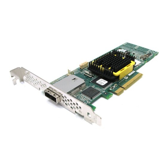
Page 31: About The Adaptec Raid 3405
About the Adaptec RAID 3405 The Adaptec RAID 3405 is a SAS RAID controller with these features: Aggregate Activity LED header for CN0 Battery connector Mounting bracket Form Factor Bus compatibility PCIe bus width PCIe bus speed Phys (Unified Serial Ports) -
Page 32: About The Adaptec Raid 3805
About the Adaptec RAID 3805 The Adaptec RAID 3805 is a SAS RAID controller with these features: Aggregate Activity LED header for CN0 Battery connector PCIe x4 connector Mounting bracket Form Factor Bus compatibility PCIe bus width PCIe bus speed... -
Page 33: About The Adaptec Raid 31205
About the Adaptec RAID 31205 The Adaptec RAID 31205 is a SAS RAID controller with these features: Activity LED Phys and connectors Activity LED Phys and connectors Alarm connector Mode 0 Flash connector Battery connector Form Factor Bus compatibility PCIe bus width... -
Page 34: About The Adaptec Raid 31605
About the Adaptec RAID 31605 The Adaptec RAID 31605 is a SAS RAID controller with these features: Activity LED Phys and connectors Activity LED Phys and connectors Alarm connector Mode 0 Flash connector Battery connector Form Factor Bus compatibility PCIe bus width... -
Page 35: About The Adaptec Raid 2045
About the Adaptec RAID 2045 The Adaptec RAID 2045 is a SAS RAID controller with these features: 1 external mini- SAS connector Form Factor Bus compatibility PCIe bus width PCIe bus speed Phys (Unified Serial Ports) Standard cache Connectors, external... -
Page 36: About The Adaptec Raid 2405/2405Q
About the Adaptec RAID 2405/2405Q The Adaptec RAID 2405/2405Q is a SAS RAID controller with these features: Form Factor Bus compatibility PCIe bus width PCIe bus speed Phys (Unified Serial Ports) Standard cache Connectors, internal Maximum number of disk drives... -
Page 37: About The Adaptec Raid 2805
About the Adaptec RAID 2805 The Adaptec RAID 2805 is a SAS RAID controller with these features: Mounting bracket Form Factor Bus compatibility PCIe bus width PCIe bus speed Phys (Unified Serial Ports) Standard cache Connectors, internal Maximum number of disk drives... -
Page 38: Getting Started
This chapter provides the basic information you need to set up your disk drives and arrays the way you want them. It also describes the options you have for installing your Adaptec controller and disk drives, and creating arrays for data storage. -
Page 39: Choosing A Raid Level
Choosing a RAID Level This section provides a brief overview of the RAID levels supported by your Adaptec RAID controller, including the minimum and maximum number of disk drives required by each. Note: Before you begin, familiarize yourself with your Adaptec controller’s physical features and the RAID levels that it supports (see RAID 0 (Non-redundant Array)—Stripes data across multiple disk drives. -
Page 40: Selecting Disk Drives And Cables
Your SAS controller supports SAS disk drives, SATA disk drives, SATA Solid State Drives (SSD), and Adaptec MaxIQ Solid State Drives. When selecting disk drives for your RAID array, ensure that all the disk drives have the same performance level. You can use different-sized disk drives in the array, but the array will be limited to the capacity of the smallest and slowest disk drive. -
Page 41: Installation Options
Adaptec Web site at www.adaptec.com. Installation Options When you install your Adaptec controller, you can choose to create a bootable array and then install your operating system and the controller driver on that array. Alternatively, you can complete a standard installation, where the controller driver is installed on an existing operating system. -
Page 42: Basic Installation Steps
Create a bootable array (see Install your operating system and the controller driver (see Install Adaptec Storage Manager and begin to manage your data storage (see Installing on an Existing Operating System Install and connect your controller and internal disk drives (see If your controller has an external connector, you can connect external disk drives as well (or instead). -
Page 43: Installing The Controller And Disk Drives
Installing the Controller... 44 Connecting Disk Drives to Your Controllers ... 46 Connecting External Devices... 50 Next Steps ... 50 This chapter explains how to install your Adaptec RAID controller, and how to install and connect internal and external disk drives. -
Page 44: Installing The Controller And Disk Drives
Handle the controller by its bracket or edges only. Installing the Controller This section describes how to install your Adaptec RAID controller into your computer cabinet. Adaptec RAID controllers come in two basic configurations: standard and zero maintenance cache protection with batteryless backup. Follow one of these sets of instructions: To install a standard series Adaptec RAID controller (without zero maintenance cache ●... -
Page 45: Installing A Raid Controller With Zero Maintenance Cache Protection
Installing a RAID Controller with Zero Maintenance Cache Protection Warning: Do not attempt to connect a Battery Backup Module (see Adaptec RAID controller with Zero Maintenance Cache Protection. The battery module can overheat and may even explode! Turn off your computer and disconnect the power cord. Open the cabinet, following the manufacturer’s instructions. -
Page 46: Connecting Disk Drives To Your Controllers
RAID level you want. See more information. Note: Although you can connect both SAS and SATA disk drives to your SAS controller, Adaptec recommends that you not combine SAS and SATA disk drives within the same array or logical drive. See page 76 for more information. -
Page 47: Connecting To A System Backplane
Chapter 5: Installing the Controller and Disk Drives Use internal SAS or mini-SAS cables to attach the disk drives to the controller, as shown in the following example. internal x4 mini-SAS connectors mini-SAS to SATA fan-out cable Note: SAS fan-out cables are also available with an additional sideband (SFF-8448) cable that caries SGPIO signals for enclosure management. -
Page 48: Connecting Maxiq Solid State Drives And Other Ssds
Connecting MaxIQ Solid State Drives and other SSDs To connect an Adaptec MaxIQ Solid State Drive or other SSD to your controller, use a direct- attached connection or a backplane connection. If your server does not have a standard 2.5- inch drive tray, you must use a bracket/SLED which enables the SSD to fit properly (not included with MaxIQ SSD kit). - Page 49 256 drives, including SSDs (for details, see Note: The following steps use an Adaptec MaxIQ SSD as an example but the procedure is suitable for any compatible SSD. Install your Adaptec MaxIQ SSDs in your server. For servers with a standard 2.5-inch drive tray, install the SSD directly into the tray.
-
Page 50: Connecting External Devices
Use high-quality cables to connect your controller to your external device(s), such as disk drives or disk drive enclosures. Adaptec recommends using only Adaptec cables. For more information or to purchase cables, visit the Adaptec Web site at www.adaptec.com. Next Steps... -
Page 51: Creating A Bootable Array
Setting the Boot Controller... 52 Creating an Array ... 52 Making Your Array Bootable ... 55 This chapter explains how to set your Adaptec controller to be the boot controller, and how to create a bootable array. Note: If you are completing a standard installation onto an existing operating system, you don’t have to complete this task. -
Page 52: Setting The Boot Controller
Note: Adaptec recommends that you not combine SAS and SATA disk drives within the same array. Adaptec Storage Manager generates a warning if you try to create a logical drive using a combination of SAS and SATA disk drives. See Creating an Array with the ACU The ACU is menu-based and instructions for completing tasks appear on-screen. - Page 53 Select Initialize Drives, then press Enter. Select at least three disk drives for the array, press Insert for each selected disk drive, then press Enter. Caution: During initialization, all data is deleted from the disk. Before continuing, back up any data you want to keep. Press Y, then press Enter.
-
Page 54: Creating An Array With Adaptec Storage Manager
Creating an Array with Adaptec Storage Manager This section describes how to use the Adaptec Storage Manager configuration wizard to build a RAID 5 array. Note: You will need the Adaptec Storage Manager Installation CD to complete this task. To create a RAID 5 array: Insert the Adaptec Storage Manager Installation CD into your CD drive, then restart your computer. -
Page 55: Making Your Array Bootable
In DAS environments, Adaptec Storage Manager uses the term logical drives when referring to arrays (see In this example, Adaptec Storage Manager has used thirteen equal-sized disk drives to automatically create one logical drive with RAID 5 and a hot spare. -
Page 56: Installing The Driver And An Operating System
Installing with VMware ... 61 Installing with FreeBSD ... 61 This chapter explains how to install your Adaptec RAID controller driver and an operating system onto a bootable array (see To install the driver on an existing operating system, see page 51). -
Page 57: Before You Begin
Before You Begin Install and connect your Adaptec RAID controller and internal disk drives (see ● Create a bootable array (see ● Create a driver disk (see the following section). ● Note: For up-to-date operating system version support, visit the Adaptec Web Site at www.adaptec.com. -
Page 58: Installing With Windows
You will need your Windows Installation CD to complete this task. Installing with Windows Server 2003 or Windows XP To install the Adaptec RAID controller driver while installing Windows: Insert your Windows CD, then restart the computer. Follow the on-screen instructions to begin the Windows installation. -
Page 59: Installing With Red Hat Linux
Installing with Red Hat Linux Note: You will need your Red Hat Installation CD to complete this task. To install the Adaptec RAID controller driver while installing Red Hat Linux: Insert the first Red Hat Installation CD. Restart your computer. -
Page 60: Installing With Unixware
When all drivers have loaded, select No. Complete the OpenServer installation, following the instructions included with your operating system. Continue with Managing Your Storage Space on page Installing with UnixWare Note: You will need your UnixWare Installation CD to complete this task. To install the driver when installing UnixWare: Insert the UnixWare Installation CD. -
Page 61: Installing With Vmware
Complete the VMware installation, following the instructions included with your operating system. Note: Currently, the Adaptec Storage Manager GUI is not supported on VMware. To create and manage arrays, you must connect to the VMware machine from a remote GUI or use the ARCCONF utility. -
Page 62: Installing The Driver On An Existing Operating System
Installing on UnixWare ... 65 Installing on Solaris... 65 Installing on VMware... 66 Installing on FreeBSD ... 66 This chapter explains how to install your Adaptec RAID controller driver. Note: To install the driver while you’re installing an operating system, see page... -
Page 63: Before You Begin
Chapter 8: Installing the Driver on an Existing Operating System Before You Begin Before you begin, install and connect your Adaptec RAID controller and internal disk drives (see page 43). You must also create a driver disk before you begin installing the controller driver. -
Page 64: Installing On Windows
Chapter 8: Installing the Driver on an Existing Operating System Installing on Windows Follow the instructions in this section for your version of Windows. Installing on Windows Server 2003 or Windows XP To install the driver on Windows: Start or restart Windows. The Found New Hardware Wizard opens and searches for the driver. -
Page 65: Installing On Openserver
To install the driver on Solaris: Start your computer. Check for any pre-existing Adaptec driver by performing a window. If there is no pre-existing Adaptec driver on your computer, continue with Step 3. If an Adaptec driver is already installed on your computer, perform a to remove it. -
Page 66: Installing On Vmware
Reboot your computer and remove the driver disk. Note: Currently, the Adaptec Storage Manager GUI is not supported on VMware. To create and manage arrays, you must connect to the VMware machine from a remote GUI or use the ARCCONF utility. -
Page 67: Managing Your Storage Space
About the Adaptec Flash Utility ... 69 Which Utility Should I Use? ... 69 Once you have installed your Adaptec RAID controller, disk drives (or other devices), and device driver, you can begin to build and manage your storage space. -
Page 68: About Adaptec Storage Manager
Adaptec Storage Manager is a full-featured software application that helps you build a storage space for your online data, using Adaptec RAID controllers and disk drives. With Adaptec Storage Manager, you can group disk drives into logical drives and build in redundancy to protect your data and improve system performance. -
Page 69: About The Adaptec Raid Configuration Utility
About the Adaptec Flash Utility The Adaptec Flash Utility (AFU) is a text-based DOS utility that you can use to update, save, or verify your RAID controller’s firmware BIOS and Non-Volatile Random Access Memory (NVRAM). -
Page 70: Solving Problems
Solving Problems In this chapter... Troubleshooting Checklist ... 71 Silencing the Alarm ... 71 Recovering from a Disk Drive Failure ... 72 Resetting the Controller... 73 This chapter provides basic troubleshooting information and solutions for solving controller problems. -
Page 71: Troubleshooting Checklist
Monitoring Disk Drives Status You can use the ‘blink’ feature of Adaptec Storage Manager to monitor the status of your SAS and SATA disk drives. When you blink a specific disk drive or set of disk drives, the LED(s) on the selected disk drives flash. -
Page 72: Recovering From A Disk Drive Failure
Make sure that the new disk drive is equal or greater in size than the failed disk drive. Then, if necessary, use Adaptec Storage Manager to rebuild the array. For instructions, refer to the Adaptec Storage Manager User’s Guide or online Help. -
Page 73: Disk Drive Failure In A Raid 0 Array
Adaptec Storage Manager. Resetting the Controller This section explains how to reset (or Mode 0 flash) your Adaptec RAID controller. You may want to do this if the controller becomes inoperable, or if a firmware upgrade is unsuccessful. - Page 74 Disconnect all cables from the controller, then attach a shorting jumper to the Mode 0 flash connector. (To locate the Mode 0 flash connector on your Adaptec RAID controller, see the figures in About Your RAID Controller on page Reconnect the power cord, power on your computer, then boot to the floppy disk containing the AFU.exe file (see...
-
Page 75: Introduction To Sas
Introduction to SAS In this appendix... Terminology Used in This Chapter ... 76 What is SAS? ... 76 How Do SAS Devices Communicate? ... 77 What’s a Phy? ... 77 What’s a SAS Port?... 78 What’s a SAS Address?... 78 What’s a SAS Connector? ... -
Page 76: Terminology Used In This Chapter
Although you can use both SAS and SATA disk drives in the same SAS domain (see 80), Adaptec recommends that you not combine SAS and SATA disk drives within the same array or logical drive. The difference in performance between the two types of disk drives may adversely affect the performance of the array. -
Page 77: How Do Sas Devices Communicate
How Do SAS Devices Communicate? SAS devices communicate with each other through links. A link is a physical connection between two phys. As shown in the following figure, SAS devices contain ports (see and each phy contains one transmitter and one receiver—one transceiver. A phy can belong to one port only. -
Page 78: What's A Sas Port
What’s a SAS Port? Note: Because the physical link between SAS devices is from phy to phy, rather than port to port, a “port” is more of a virtual concept, different from what is normally considered a port on other types of RAID controllers and storage devices. A port is one or more phys. -
Page 79: How Are Disk Drives Identified In Sas
About Your RAID Controller on page 17 LED connections and locations. Once you have connected to a backplane, use Adaptec Storage Manager to manage your disk drives. For more information, refer to the Adaptec Storage Manager User’s Guide on the Adaptec Storage Manager Installation CD. -
Page 80: Sas Expander Connections
Some backplanes support daisy-chain expansion to other backplanes. For example, you can daisy-chain (connect one to the next) up to nine Adaptec S50 enclosures to a single SAS card in a host system. SAS Expander Connections A SAS expander device literally expands the number of end devices that you can connect together. -
Page 81: How Is Sas Different From Parallel Scsi
How is SAS Different from Parallel SCSI? In summary, although SAS and parallel SCSI both use the SCSI command set, how they move data from one place to another is very different. To support point-to-point serial data transport, SAS introduces new types of connectors, cables, connection options, and terminology. -
Page 82: Understanding Raid
This appendix describes the RAID levels supported by your Adaptec RAID controller, and provides a basic overview of each to help you select the best level of protection for your data... -
Page 83: Understanding Drive Segments
Understanding Drive Segments A drive segment is a disk drive or portion of a disk drive that is used to create an array. A disk drive can include both RAID segments (segments that are part of an array) and available segments. -
Page 84: Raid 1 Arrays
RAID 1 Arrays A RAID 1 array is built from two disk drives, where one disk drive is a mirror of the other (the same data is stored on each disk drive). Compared to independent disk drives, RAID 1 arrays provide improved performance, with twice the read rate and an equal write rate of single disks. -
Page 85: Raid 10 Arrays
RAID 10 Arrays A RAID 10 array is built from two or more equal-sized RAID 1 arrays. Data in a RAID 10 array is both striped and mirrored. Mirroring provides data protection, and striping improves performance. Drive segment size is limited to the size of the smallest disk drive in the array. For instance, an array with two 250 GB disk drives and two 400 GB disk drives can create two mirrored drive segments of 250 GB, for a total of 500 GB for the array, as shown in this figure. -
Page 86: Raid 5 Arrays
RAID 5 Arrays A RAID 5 array is built from a minimum of three disk drives, and uses data striping and parity data to provide redundancy. Parity data provides data protection, and striping improves performance. Parity data is an error-correcting redundancy that’s used to re-create data if a disk drive fails. In RAID 5 arrays, parity data (represented by Ps in the next figure) is striped evenly across the disk drives with the stored data. -
Page 87: Raid 5Ee Arrays
RAID 5EE Arrays A RAID 5EE array—also known as a hot space—is similar to a RAID 5 array except that it includes a distributed spare drive and must be built from a minimum of four disk drives. Unlike a hot spare, a distributed spare is striped evenly across the disk drives with the stored data and parity data, and can’t be shared with other logical disk drives. -
Page 88: Raid 50 Arrays
RAID 50 Arrays A RAID 50 array is built from six to forty-eight disk drives configured as two or more RAID 5 arrays, and stripes stored data and parity data across all disk drives in both RAID 5 arrays. (For more information, see RAID 5 Arrays on page The parity data provides data protection, and striping improves performance. -
Page 89: Raid 6 Arrays
RAID 6 Arrays A RAID 6 array—also known as dual drive failure protection—is similar to a RAID 5 array because it uses data striping and parity data to provide redundancy. However, RAID 6 arrays include two independent sets of parity data instead of one. Both sets of parity data are striped separately across all disk drives in the array. -
Page 90: Selecting The Best Raid Level
Selecting the Best RAID Level Use this table to select the RAID levels that are most appropriate for the logical drives on your storage space, based on the number of available disk drives and your requirements for performance and reliability. RAID Level Redundancy RAID 0... -
Page 91: Using The Adaptec Raid Configuration Utility
Locating Disk Drives ... 100 Identifying Disk Drives ... 100 Viewing the Event Log ... 102 The Adaptec RAID Configuration (ARC) utility is a BIOS-based utility that you can use to create and manage controllers, disk drives and other devices, and arrays. Note:... -
Page 92: Introduction To The Arc Utility
Disk Utilities—For formatting or verifying disk drives (see ● Running the ARC Utility If your Adaptec controller is connected to a RAID enclosure, power on your enclosure (or enclosures) before you power on your computer. Start or restart your computer. When prompted, press Ctrl+A. -
Page 93: Managing Existing Arrays
Power management settings switch the array to low power state when it is inactive for a specific time. Note: These settings apply to Adaptec 5-series and 2-series controllers only. (3-series controllers do not support power management.) To modify power management settings: Select Manage Arrays from the main ACU menu. -
Page 94: Initializing Disk Drives
Appendix C: Using the Adaptec RAID Configuration Utility In the power management console, enter these details: Option Description Power Management When enabled, switches the array to low power state, when the array/ drive is inactive. Slow Down Drive After The duration of inactive state of the array/drive after which it is slowed down to low power mode. -
Page 95: Rescanning Disk Drives
(see page 99) instead, or clear it using Adaptec Storage Manager—both options take much less time than the secure erase option. To begin a secure erase, select Secure Erase from the main ACU menu, then select Y (yes). To return to the main ACU menu once the secure erase has begun, press Esc. -
Page 96: Using The Acu To Create And Manage Jbods
MaxIQ caching.) You can configure the MaxIQ pool only if you have one or more MaxIQ-compatible Solid State Drives installed on the RAID controllers in your system. For a list of MaxIQ-compatible SSDs, refer to the Adaptec Web site at www.adaptec.com/compatibility. -
Page 97: Using Serialselect To Modify Controller Settings
Any changes you made take effect after the computer restarts. Modifying Your Controller’s Configuration Note: Default controller settings are suitable for most computers. Adaptec recommends that you do not change the default setting. To modify your controller’s basic settings, select Controller Configuration from the main SerialSelect menu. - Page 98 When set to Enable All, write cache is enabled on all disk drives on the controller. (Enabling the write cache overrides any individual drive settings in Adaptec Storage Manager.) When set to Disable All, write cache is not used on the disk drives. When set to Drive Specific, write cache is enabled/disabled on a per-drive basis in Adaptec Storage Manager.
-
Page 99: Formatting And Verifying Disk Drives
Spin Up Limit (External) PHY Settings Note: For 3-series controllers, these settings are read-only and non-editable. These settings are not available on the Adaptec RAID 31205 and Adaptec RAID 31605 controllers. Option Description PHY Rate The data transfer rate between the controller and devices. The default setting is Auto, which allows the SAS card to adjust the data transfer rate, as needed. -
Page 100: Locating Disk Drives
The location information of a disk drive is determined by three types of connections: Direct attached drives ● for example CN1 (connector 1) is connected to DEV1 (device 1). For more information, see Direct-attach Connections Appendix C: Using the Adaptec RAID Configuration Utility page 92). page 92). - Page 101 Appendix C: Using the Adaptec RAID Configuration Utility Storage Enclosure Processor (SEP) managed devices ● active backplane. Box0 (enclosure 0) is connected to slot0 (disk drive slot 0 in the enclosure). For more information, see Expanders ● —The connections is determined by an expander. Exp0 (expander 0) is connected to phy0 (phy 0 within a connector).
-
Page 102: Viewing The Event Log
Select the controller you want, then press Enter. When the ARC utility menu appears, then press Ctrl+P. Select Controller Log Information, then press Enter. The current event log opens. Appendix C: Using the Adaptec RAID Configuration Utility page 92). ●... -
Page 103: Using The Array Configuration Utility For Dos
(A BIOS-based ACU is also available. See page 92.) Note: Adaptec recommends that only advanced users familiar with working in DOS use the ACU for DOS utility. For more information, see Managing Your Storage Space on page... -
Page 104: Getting Started
Insert your RAID Controller Installation CD into the CD drive, then browse to this file: packages/firmware/controllermodel/acu.exe Where controllermodel is the model number of your Adaptec RAID controller. Insert a bootable floppy disk and copy the acu.exe file to it. Continue in one of two ways: Work in the ACU using menus (see the following section) ●... -
Page 105: Running The Acu Using Scripts
Running the ACU Using Scripts To work in the ACU using scripts: Insert the ACU floppy disk (see The computer boots to the DOS command line. Type on the command line, specify a script file, and specify either the /P or /R switches listed in the following table. -
Page 106: About Record Mode
Appendix D: Using the Array Configuration Utility for DOS About Record Mode Note: You can also create a script file manually (see the following section). In Record Mode, the ACU writes a RAID controller’s existing array configuration to a specified script file, which lets you create the same configuration by running the ACU in Playback Mode (/P switch) with the resulting script. -
Page 107: Array Definition Block Keywords
Appendix D: Using the Array Configuration Utility for DOS Array Definition Block Keywords The array definition block always begins with the keyword Array and ends with the keyword End. The other required array definition keywords are Drives and Type. Array definition keywords and descriptions are listed in this table. Keyword Required? Description Array... - Page 108 Appendix D: Using the Array Configuration Utility for DOS For example: Drives=0:0:0 Drives=0:0:0,0:1:0,0:2:0 End Keyword End is a required keyword, indicating the end of the block. HotspareDrives Keyword Hotspare Drives is an optional keyword, specifying the hot spares to assign to the array. The syntax for listing hot spares is the same as the is not specified, no hot spares are assigned to the array.
- Page 109 Appendix D: Using the Array Configuration Utility for DOS Method Keyword Method is an optional keyword, indicating which method to use when creating a redundant (RAID 1, 1E, 10, 5, 5EE, 50, 6 and 60) array. Possible values: Build (the default)—Perform a Build/Verify process on the array. Takes longer than Clear, ●...
-
Page 110: Acu Error Codes
Appendix D: Using the Array Configuration Utility for DOS For example: StripeSize=256 Type Keyword Type is a required keyword, indicating the array type. There is no default value. The possible values: Volume, RAID0, RAID1, RAID5, RAID10, or RAID50. Depending on the RAID levels supported by your RAID controller, additional possible values are: RAID1E, RAID5EE, RAID6, RAID60. -
Page 111: Sample Scripts
Appendix D: Using the Array Configuration Utility for DOS Code Description Unable to read system configuration—The ACU was unable to get the configuration information from the specified controller. No drives detected. Specified drive not found in system. Specified array size too small—You specified an array size that is smaller than the minimum size allowed for this array. - Page 112 Appendix D: Using the Array Configuration Utility for DOS ● # Use drives 1 and 2 Drives=0:1:0,0:2:0 # Disable write cache WriteCache=No # Assign 1 spare drive HotspareDrives=0:3:0 This sample script file creates a maximum-size three-disk-drive RAID 5: # Create a maximum size RAID 5 labeled ‘MyData’ Array=MyData Type=RAID5 Size=Maximum...
-
Page 113: Using The Adaptec Flash Utility
Updating the Flash Using the AFU Command Line ... 119 This chapter describes how to use the Adaptec Flash Utility (AFU), a text-based DOS utility that you can use to update, save, or verify the RAID controller’s firmware BIOS and NVRAM. -
Page 114: System Requirements
The RAID Controller Installation CD—Includes the AFU executable (AFU.exe) and a ● separate flash image. The flash image may comprise multiple User Flash Image (UFI) files. The Adaptec Web site—Download a new firmware file to get the most recent version of ● firmware/BIOS and AFU. -
Page 115: Creating The Firmware Update Disks
Note: Most controller model numbers have a suffix (for example Adaptec RAID 3405). Check that the .ufi file is the correct file for your controller before copying. If using floppy disks, copy each additional Axxxx0x.ufi file to a separate floppy disk. (Some RAID controllers have two UFI files;... -
Page 116: Running The Afu From The Command Line
You must restart the computer following a SAVE command. The command syntax for the SAVE command is AFU SAVE [/C<Controller ID>] [/D <UFI File Path>] Appendix E: Using the Adaptec Flash Utility page 115). page 116) and any switches ●... - Page 117 (c)Adaptec Inc. 1999–2005. All Rights Reserved. Updating Controller 0 (Adaptec RAID 31205) Reading flash image file (Build 5749) AFU is about to update firmware on controllers Adaptec RAID 31205 ***PLEASE DO NOT REBOOT THE SYSTEM DURING THE UPDATE*** This might take a few minutes.
- Page 118 A:\> AFU VERSION /C 0 Adaptec Flash Utility V4.0-0 B5749 (c)Adaptec Inc. 1999–2005. All Rights Reserved. Version Information for Controller #0 (Adaptec RAID 31205) ROM: Build 5748 [VALID] Fri Sep 27 13:28:40 EDT 2005 A:\> AFU VERSION /C ALL Help Displays a summary of AFU functions and command switches.
-
Page 119: Updating The Flash Using The Afu Command Line
To update multiple RAID controllers: ● AFU UPDATE /C <cont_number_a>,<cont_number_b> Where <controller_number_a> and <controller_number_b> are the numbers of the Adaptec RAID controllers whose firmware you are updating. For example, to upgrade controllers 0, 2, and 3, type To update all RAID controllers simultaneously: ●... -
Page 120: Controller Led And I2C Connector Quick Reference
Adaptec RAID 5405/5405Z LED and I2C Connector Specification... 123 Adaptec RAID 5445/5445Z LED and I2C Connector Specification... 124 Adaptec RAID 5805/5805Q/5805Z/5805ZQ LED and I2C Connector Specification ... 126 Adaptec RAID 51245 LED and I2C Connector Specification... 128 Adaptec RAID 51645 LED and I2C Connector Specification... 130 Adaptec RAID 52445 LED and I2C Connector Specification... -
Page 121: Adaptec Raid 5085 Led Connector Specification
Appendix F: Controller LED and I2C Connector Quick Reference Adaptec RAID 5085 LED Connector Specification 2249100-R Adaptec RAID 5085 Activity LED Header Connector: Molex 10-89-7162 or equivalent ● Activity LED Header Mating Cable Connector: Molex 22-55-2161 or equivalent ● J2 Pin Number Signal +3.3V... - Page 122 Appendix F: Controller LED and I2C Connector Quick Reference J12: J12 Pin Number Signal ~2kHz Square Wave +3.3V Adaptec RAID 5085 Status LED Board Connector: Molex 10-89-7162 or equivalent ● Status LED Mating Cable Connector: Molex 22-55-2161 or equivalent ● J14: J14 Pin Number Signal +3.3V...
-
Page 123: Adaptec Raid 5405/5405Z Led And I2C Connector Specification
Alarm Mating Cable Connector: Molex 50-57-9002 or equivalent ● J12: J12 Pin Number Signal ~2kHz Square Wave +3.3V Adaptec RAID 5405/5405Z I2C Board Connector : Molex 22-43-6030 or equivalent ● ASR-5405 RoHS KIT ASR-5405/JA RoHS KIT ASR-5405 RoHS Single ASR-5405Z RoHS Single Description... -
Page 124: Adaptec Raid 5445/5445Z Led And I2C Connector Specification
Activity LED Header Mating Cable Connector: Molex 22-55-2161 or equivalent ● Note: For Adaptec RAID 5445, header J2 is a 16-pin connector (pins 1-16). For Adaptec RAID 5445Z, header J2 is an 8-pin connector (pins 1-8 only). J2 Pin Number Signal +3.3V... - Page 125 Alarm Mating Cable Connector: Molex 50-57-9002 or equivalent ● J12: J12 Pin Number Signal ~2kHz Square Wave +3.3V Adaptec RAID 5445/5445Z I2C Board Connector : Molex 22-43-6030 or equivalent ● I2C Mating Cable Connector: Molex 22-43-3030 or equivalent ● J4 Pin Number Signal I2C Clock...
-
Page 126: Adaptec Raid 5805/5805Q/5805Z/5805Zq Led And I2C Connector Specification
Adaptec RAID 5805/5805Q/5805Z/5805ZQ LED and I2C Connector Specification 2244100-R 2244100JA-R 2244300-R 2266900-R 2268500-R 2268600-R Adaptec RAID 5805/5805Q/5805Z/5805ZQ Activity LED Header Connector: Molex 10- ● 89-7162 or equivalent Activity LED Header Mating Cable Connector: Molex 22-55-2161 or equivalent ● J2 Pin Number Signal +3.3V ACTIVITY CN0, LANE 0 +3.3V... - Page 127 Alarm Mating Cable Connector: Molex 50-57-9002 or equivalent ● J12: J12 Pin Number Signal ~2kHz Square Wave +3.3V Adaptec RAID 5805/5805Q/5805Z/5805ZQ I2C CN0 Board Connector : Molex 22-43- ● 6030 or equivalent I2C Mating Cable Connector: Molex 22-43-3030 or equivalent ● J4 Pin Number Signal...
-
Page 128: Adaptec Raid 51245 Led And I2C Connector Specification
+3.3V STATUS CN1, LANE 3 Adaptec RAID 51245 LED and I2C Connector Specification 2258400-R 2258300-R Adaptec RAID 51245 Activity LED Header Connector for CN0/CN1: Molex 10-89-7162 ● or equivalent Activity LED Header Mating Cable Connector: Molex 22-55-2161 or equivalent ●... - Page 129 ACTIVITY CN0, LANE 1 +3.3V ACTIVITY CN0, LANE 2 +3.3V ACTIVITY CN0, LANE 3 Adaptec RAID 51245 Activity LED Board Connector for CN2: Molex 10-89-7162 or ● equivalent Activity LED Mating Cable Connector: Molex 22-55-2161 or equivalent ● J1 Pin Number...
-
Page 130: Adaptec Raid 51645 Led And I2C Connector Specification
Appendix F: Controller LED and I2C Connector Quick Reference Adaptec RAID 51245 Aggregate Activity LED Board Connector: Molex 22-28-4023 or ● equivalent Aggregate LED Mating Cable Connector: Molex 50-57-9002 or equivalent ● J10: J10 Pin Number Signal ACTIVITY +3.3V Adaptec RAID 51245 External Alarm Connector: Molex 22-28-4023 or equivalent ●... - Page 131 ACTIVITY CN0, LANE 1 +3.3V ACTIVITY CN0, LANE 2 +3.3V ACTIVITY CN0, LANE 3 Adaptec RAID 51645 Activity LED Board Connector for CN2/CN3: Molex 10-89-7162 or ● equivalent Activity LED Mating Cable Connector: Molex 22-55-2161 or equivalent ● J1 Pin Number Signal +3.3V...
-
Page 132: Adaptec Raid 52445 Led And I2C Connector Specification
Alarm Mating Cable Connector: Molex 50-57-9002 or equivalent ● J12: J12 Pin Number Signal ~2kHz Square Wave +3.3V Adaptec RAID 51645 I2C Board Connector : Molex 22-43-6030 or equivalent ● I2C Mating Cable Connector: Molex 22-43-3030 or equivalent ● J27, J28, J29, J30: J2x Pin Number Signal... - Page 133 ACTIVITY CN0, LANE 1 +3.3V ACTIVITY CN0, LANE 2 +3.3V ACTIVITY CN0, LANE 3 Adaptec RAID 52445 Activity LED Board Connector for CN2/CN3: Molex 10-89-7162 or ● equivalent Activity LED Mating Cable Connector: Molex 22-55-2161 or equivalent ● J1 Pin Number Signal +3.3V...
- Page 134 +3.3V ACTIVITY CN5, LANE 1 +3.3V ACTIVITY CN5, LANE 2 +3.3V ACTIVITY CN5, LANE 3 Adaptec RAID 52445 Aggregate Activity LED Board Connector: Molex 22-28-4023 or ● equivalent Aggregate LED Mating Cable Connector: Molex 50-57-9002 or equivalent ● J10: J10 Pin Number...
-
Page 135: Adaptec Raid 3085 Led Connector Specification
+3.3V ACT0_7_LED_L (7) Adaptec RAID 3405 LED and I2C Connector Specification 2251800-R 2251800JA-R 2251900-R Adaptec RAID 3405 LED Board Connector: Molex 10-89-7162 2.54mm 2x8 Header or ● equivalent. LED Mating Cable Connector: Molex 22-55-2081 or equivalent. ● ASR-3085 RoHS Kit... - Page 136 ACT0_7_LED_L (7) +3.3V ACT0_7_LED_L (6) +3.3V ACT0_7_LED_L (5) +3.3V ACT0_7_LED_L (4) Adaptec RAID 3405 Aggregate Activity LED Board Connector: Molex 22-28-8022 ● 2.54mm 1x2 RA Header or equivalent. LED Mating Cable Connector: Molex 50-57-9002 or equivalent. ● J12: Pin Number...
-
Page 137: Adaptec Raid 3805 Led And I2C Connector Specification
BACKPLANE_TYPEB Adaptec RAID 3805 LED and I2C Connector Specification 2252100-R 2252100JA-R 2252200-R 2252300-R Adaptec RAID 3805 LED Board Connector: Molex 10-89-7162 2.54mm 2x8 Header or ● equivalent LED Mating Cable Connector: Molex 22-55-2161 or equivalent ● J10: J10 Pin Number Signal +3.3V... - Page 138 Appendix F: Controller LED and I2C Connector Quick Reference J11: Pin Number Signal AGGREGATE0_3_L +3.3V Adaptec RAID 3805 Aggregate Activity LED Board Connector: Molex 22-28-8022 ● 2.54mm 1x2 RA Header or equivalent LED Mating Cable Connector: Molex 50-57-9002 or equivalent ● J12:...
-
Page 139: Adaptec Raid 31205 Led And I2C Connector Specification
SB5_CONB CONTROLLER_TYPEB_BUF BACKPLANE_TYPEB Adaptec RAID 31205 LED and I2C Connector Specification 2252500-R 2252400-R Adaptec RAID 31205 LED Board Connector: Molex 10-89-7162 2.54mm 2x8 Header or ● equivalent LED Mating Cable Connector: Molex 22-55-2161 or equivalent ● J10: J10 Pin Number Signal +3.3V... - Page 140 Appendix F: Controller LED and I2C Connector Quick Reference J10 Pin Number Signal +3.3V ACT0_7_LED_L (7) Adaptec RAID 31205 LED Board Connector: Molex 10-89-7162 2.54mm 2x8 Header or ● equivalent LED Mating Cable Connector: Molex 22-55-2081 or equivalent ● J17:...
- Page 141 J15: Pin Number Signal AGGREGATE8_11_L +3.3V Adaptec RAID 31205 I2C Board Connector: Molex 22-43-6030 or equivalent ● I2C Mating Cable Connector: Molex 22-43-3030 or equivalent ● The following pins are tied to Sideband Signals of SFF-8087 connector J3 (Ports 0-3)
-
Page 142: Adaptec Raid 31605 Led And I2C Connector Specification
SB5_CONC CONTROLLER_TYPEC_BUF BACKPLANE_TYPEC Adaptec RAID 31605 LED and I2C Connector Specification 2252800-R 2252700-R Adaptec RAID 31605 LED Board Connector: Molex 10-89-7162 2.54mm 2x8 Header or ● equivalent LED Mating Cable Connector: Molex 22-55-2161 or equivalent ● I2C Description SB4 - Reset SB5 - Backplane Address SB6 –... - Page 143 +3.3V ACT0_7_LED_L (4) +3.3V ACT0_7_LED_L (5) +3.3V ACT0_7_LED_L (6) +3.3V ACT0_7_LED_L (7) Adaptec RAID 31605 LED Board Connector: Molex 10-89-7162 2.54mm 2x8 Header or ● equivalent LED Mating Cable Connector: Molex 22-55-2161 or equivalent ● J17: Board Pin Number Signal +3.3V...
- Page 144 Appendix F: Controller LED and I2C Connector Quick Reference Adaptec RAID 31605 Aggregate Activity LED Board Connector: Molex 22-28-8022 ● 2.54mm 1x2 RA Header or equivalent LED Mating Cable Connector: Molex 50-57-9002 or equivalent ● J11: Pin Number Signal AGGREGATE0_3_L +3.3V...
- Page 145 The following pins are tied to Sideband Signals of SFF-8087 connector J3 (Ports 0-3) Pin Number Signal SDA_A SCL_A Adaptec RAID 31605 I2C Board Connector: Molex 22-43-6030 or equivalent ● I2C Mating Cable Connector: Molex 22-43-3030 or equivalent ● The following pins are tied to Sideband Signals of SFF-8087 connector J5 (Ports 0-3)
- Page 146 Appendix F: Controller LED and I2C Connector Quick Reference Pin Number Signal SB4_CONA SB5_CONA CONTROLLER_TYPEA_BUF BACKPLANE_TYPEA SFF-8087 Connector J5: Pin Number Signal SB0_CONB SB1_CONB SB4_CONB SB5_CONB CONTROLLER_TYPEB_BUF BACKPLANE_TYPEB SFF-8087 Connector J18: Pin Number Signal SB0_CONC SB1_CONC SB4_CONC SB5_CONC CONTROLLER_TYPEC_BUF BACKPLANE_TYPEC SFF-8087 Connector J14: Pin Number Signal...
-
Page 147: Adaptec Raid 2045 Led Connector Specification
Appendix F: Controller LED and I2C Connector Quick Reference Adaptec RAID 2045 LED Connector Specification 2260300-R Adaptec RAID 2045 Aggregate Activity LED Board Connector: Molex 22-28-4023 or ● equivalent Aggregate LED Mating Cable Connector: Molex 50-57-9002 or equivalent ● J1 Pin Number Signal ACTIVITY +3.3V... -
Page 148: Adaptec Raid 2805 Led And I2C Connector Specification
Appendix F: Controller LED and I2C Connector Quick Reference J1 Pin Number Signal ACTIVITY +3.3V Adaptec RAID 2405/2405Q I2C Board Connector : Molex 22-43-6030 or equivalent ● I2C Mating Cable Connector: Molex 22-43-3030 or equivalent ● J4 Pin Number Signal... - Page 149 Aggregate LED Mating Cable Connector: Molex 50-57-9002 or equivalent ● J1 Pin Number Signal ACTIVITY +3.3V Adaptec RAID 2805 I2C CN0 Board Connector : Molex 22-43-6030 or equivalent ● I2C Mating Cable Connector: Molex 22-43-3030 or equivalent ● J4 Pin Number...
-
Page 150: Safety Information
● board or the connectors. Put the controller down only on an antistatic surface such as the bag supplied in your kit. ● If you are returning the controller to Adaptec, put it back in its antistatic bag immediately. ●... -
Page 151: Technical Specifications
Technical Specifications In this appendix... Environmental Specifications... 152 DC Power Requirements... 152 Current Requirements... 152... -
Page 152: Adaptec Raid 2405/2405Q Adaptec Raid
Environmental Specifications Note: Adaptec RAID controllers require adequate airflow to operate reliably. The recommended airflow is 200 LFM. Forced airflow is recommended. Ambient temperature with forced airflow Ambient temperature without forced airflow Ambient temperature with Battery Backup Unit (BBU) Relative humidity... - Page 153 Adaptec customer support Adaptec Flash Utility. See AFU Adaptec RAID Configuration utility Adaptec RAID Controller Configuration utility. See ARCCONF Adaptec Storage Manager creating arrays installing adapters. See controllers advanced data protection Alarm Control setting...
- Page 154 bootable arrays creating cards. See controllers CD-ROM Boot Support setting command line interface (flash utility) command line utility connectors contents of controller kit controllers activity LED connector specifications Alarm Control setting Array Background Consistency Check setting Array-based BBS Support setting array-level features Automatic Failover setting CD-ROM Boot Support setting...
- Page 155 expander connections expander devices external devices failed disk drives multiple arrays multiple disk drives RAID 0 arrays without hot spare firmware creating floppy disks firmware upgrades flashing controllers floppy disks for firmware update formatting disk drives FreeBSD driver installation OS installation hard disk, hard disk drive, hard drive.
- Page 156 Solaris driver installation Solid State Drive (SSD) 18, 40, 46, 94, installing specifications storage management Adaptec RAID Configuration utility Adaptec Storage Manager ARCCONF storage space support, customer SUSE driver installation SUSE installation switches in ACU for DOS system requirements...
- Page 157 UnixWare driver installation OS installation updating firmware upgrading firmware utilities Adaptec RAID Controller utility ARCCONF verifying disk drives VMWare driver installation OS installation Windows driver installation OS installation zero maintenance cache protection 18, 44, zero maintenance module (ZMM) Index ●...
- Page 158 Adaptec, Inc. 691 South Milpitas Boulevard Milpitas, CA 95035 USA ©2010 Adaptec, Inc. All rights reserved. Adaptec and the Adaptec logo are trademarks of Adaptec, Inc. which may be registered in some jurisdictions. Part Number: CDP-00194-03-A Rev. A JB 07/10...
Need help?
Do you have a question about the 3405 and is the answer not in the manual?
Questions and answers