Table of Contents
Advertisement
Advertisement
Table of Contents

Related Manuals for Metrohm 883 Basic IC plus


Summary of Contents for Metrohm 883 Basic IC plus
- Page 1 883 Basic IC plus 2.883.0020 Manual 8.883.8001EN / 2019-12-12...
- Page 3 Metrohm AG CH-9100 Herisau Switzerland Phone +41 71 353 85 85 Fax +41 71 353 89 01 info@metrohm.com www.metrohm.com 883 Basic IC plus 2.883.0020 Manual 8.883.8001EN / 2019-12-12...
- Page 4 Technical Communication Metrohm AG CH-9100 Herisau techcom@metrohm.com This documentation is protected by copyright. All rights reserved. This documentation has been prepared with great care. However, errors can never be entirely ruled out. Please send comments regarding possible errors to the address above.
-
Page 5: Table Of Contents
3.10 Installing an inline filter ............. 27 3.11 Installing the pulsation absorber ........28 3.12 Injection valve ..............29 3.13 Suppressor ................31 3.13.1 General information on the suppressor ........31 3.13.2 Installing the suppressor ............31 883 Basic IC plus ■■■■■■■■... - Page 6 4 Operation and maintenance IC system ................56 4.1.1 Operation ................56 4.1.2 Care ..................56 4.1.3 Maintenance by Metrohm Service .......... 56 4.1.4 Shutting down and recommissioning ........57 Capillary connections ............58 Door ..................58 Handling the eluent ............58 4.4.1 Manufacturing eluent ............
- Page 7 Ambient conditions ............93 Housing ................94 Injection valve ..............94 Suppressor ................94 Peristaltic pump ..............95 Detector ................95 Power connection ............... 95 6.10 Interfaces ................95 6.11 Weight ................. 96 7 Accessories Index 883 Basic IC plus ■■■■■■■■...
- Page 8 Figure 1 883 Basic IC plus front ............... 6 Figure 2 883 Basic IC plus rear ................ 7 Figure 3 Installation diagram 883 Basic IC plus ..........12 Figure 4 Positioning the detector ..............17 Figure 5 Drainage tubing ................20 Figure 6 Capillary feed-throughs on the door ..........
-
Page 9: Introduction
1 Introduction 1 Introduction Instrument description The 883 Basic IC plus is an intelligent, very compact ion chromatograph for education and routine analysis. The instrument is distinguished by: the intelligence of its components, which are able to monitor, opti- ■... -
Page 10: Intended Use
This instrument is suitable for processing chemicals and flammable sam- ples. Therefore, the use of the 883 Basic IC plus requires the user to have basic knowledge and experience in handling toxic and caustic substances. Knowledge regarding the application of fire prevention measures prescri- bed for laboratories is also mandatory. -
Page 11: Safety Instructions
The electrical safety when working with the instrument is ensured as part of the international standard IEC 61010. WARNING Only personnel qualified by Metrohm are authorized to carry out service work on electronic components. WARNING Never open the housing of the instrument. The instrument could be damaged by this. -
Page 12: Tubing And Capillary Connections
Recycling and disposal This product is covered by European Directive 2012/19/EU, WEEE – Waste Electrical and Electronic Equipment. The correct disposal of your old instrument will help to prevent negative effects on the environment and public health. ■■■■■■■■ 883 Basic IC plus... -
Page 13: Symbols And Conventions
WARNING This symbol draws attention to a possible biological hazard. CAUTION This symbol draws attention to possible damage to instruments or instrument parts. NOTE This symbol highlights additional information and tips. 883 Basic IC plus ■■■■■■■■... -
Page 14: Overview Of The Instrument
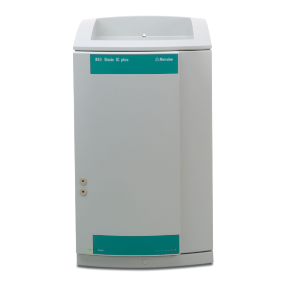
2.1 Front ■■■■■■■■■■■■■■■■■■■■■■ 2 Overview of the instrument Front Figure 1 883 Basic IC plus front Detector chamber Door Space for the detector. With Luer connector and capillary feed- through. High-pressure pump Metrohm Suppressor Module. Column holder Peristaltic pump With chip recognition for iColumns. -
Page 15: Rear
■■■■■■■■■■■■■■■■■■■■■■ 2 Overview of the instrument Rear Figure 2 883 Basic IC plus rear On/off switch Power socket PC connection socket Detector connection socket Transport locking screws Knurled screws For fastening the removable back panel. Back panel Capillary feed-throughs Removable. Access to the detector chamber. -
Page 16: Installation
Some of the capillaries are already connected when the instrument is delivered. You still have to carry out the following steps: Installing the 883 Basic IC plus 1 Setting up the instrument (see chapter 3.4, page 14). 2 Installations on the rear of the instrument Place the detector in the instrument and connect it (see chapter ■... - Page 17 (6.1826.320) (3-9) using a tubing olive (6.2744.034) (3-16) and a short pressure screw (6.2744.070) (3-15). Shorten it to the required length. Place the pump tubing in a tubing cartridge. ■ Insert the tubing cartridge into the peristaltic pump. ■ 883 Basic IC plus ■■■■■■■■...
- Page 18 Connect the guard column (optional) (see chapter 3.19, page ■ 49). – Connect the guard column to the end of the column inlet capillary as described in the leaflet supplied with the guard column. – Rinse the guard column. ■■■■■■■■ 883 Basic IC plus...
-
Page 19: Installation Diagram
The following installation diagram shows a schematic of the front of the instrument after installation is complete. Some of the capillaries are already installed when the instrument is delivered; these capillaries are not numbered in the diagram. Numbered capillaries have to be connected during installation. 883 Basic IC plus ■■■■■■■■... -
Page 20: Figure 3 Installation Diagram 883 Basic Ic Plus
3.3 Installation diagram ■■■■■■■■■■■■■■■■■■■■■■ 15 16 Figure 3 Installation diagram 883 Basic IC plus Eluent aspiration tubing (6.1834.080) PEEK capillary (6.1831.100) As column input capillary. ■■■■■■■■ 883 Basic IC plus... - Page 21 17 Pump tubing connection (6.2744.180) 18 Coupling (6.2744.040) With locking nut and filter, for connecting capillaries to the outlet side of the peristaltic pump. 19 PTFE capillary (6.1803.040) 20 PTFE capillary (6.1803.040) Sample aspiration capillary. Sample output capillary. 883 Basic IC plus ■■■■■■■■...
-
Page 22: Setting Up The Instrument
PEEK capillaries are pressure-stable up to 400 bar (depending on the inner etheretherketone) diameter), flexible, chemically inert and have an extremely smooth surface. They can be readily cut down to the desired length with the capillary cut- ter (6.2621.080). Use: ■■■■■■■■ 883 Basic IC plus... - Page 23 One prerequisite for dead-volume-free capillary connection is that both capillary ends are cut exactly flat. Therefore we recommend cutting PEEK capillaries only with a capillary cutter (6.2621.080). Also see: Cutting capillaries video on the Internet http://ic- help.metrohm.com. 883 Basic IC plus ■■■■■■■■...
- Page 24 2 Heat the colored sleeve, e.g. with a hairdryer. The colored sleeve shrinks and adapts to the shape of the capillary. NOTICE In order to arrange capillaries more clearly, they can be bundled with the spiral band (6.1815.010). ■■■■■■■■ 883 Basic IC plus...
-
Page 25: Installations On The Rear Of The Instrument
3 Installation Installations on the rear of the instrument 3.6.1 Positioning and connecting the detector Figure 4 Positioning the detector Knurled screws Back panel For fastening the removable back panel. Removable. Access to the detector chamber. 883 Basic IC plus ■■■■■■■■... -
Page 26: Transport Locking Screws
These are located at the rear of the instrument and labeled with Transport security screws (2-5). Remove these transport locking screws before the initial start-up. Accessories For this step you need: ■■■■■■■■ 883 Basic IC plus... -
Page 27: Installing The Drainage Tubing
The pump may be damaged if you transport the instrument without inserting the transport locking screws. 3.6.3 Installing the drainage tubing Liquid that leaks in the bottle holder or in the detector chamber is con- veyed via the drainage tubing into the waste container. 883 Basic IC plus ■■■■■■■■... -
Page 28: Figure 5 Drainage Tubing
For draining leaked liquid from the detector Section. For draining leaked liquid from the chamber. detector chamber. Y connector (6.1807.010) Silicone tubing (6.1816.020) For connecting the two drainage tubings Section. Conveys the leaked liquid to the waste container. ) and (5- ■■■■■■■■ 883 Basic IC plus... -
Page 29: Capillary And Cable Feed-Throughs
Capillary and cable feed-throughs Several openings have been integrated for feeding through capillaries and cables. These can be found at the door (6-4), and at the rear panel (2-8). 883 Basic IC plus ■■■■■■■■... -
Page 30: Figure 6 Capillary Feed-Throughs On The Door
Do not feed capillaries through the Luer connectors (6-1). The capillaries are fastened with PEEK pressure screws (6-3) from inside to the Luer con- nector. From outside, liquid can be aspirated or injected with a syringe. ■■■■■■■■ 883 Basic IC plus... -
Page 31: Connecting The Eluent Bottle
M8 opening of the bottle cap and screw it on for the time being. Figure 7 Installing the eluent bottle cap 2 Mounting the tubing adapter Install the parts of the tubing adapter for aspiration filter (6.2744.210) accessory set: 883 Basic IC plus ■■■■■■■■... - Page 32 Place the loose end of the eluent aspiration tubing into the aspira- ■ tion filter. The end of the tubing should reach approximately to the center of the aspiration filter. Tighten the aspiration filter to the filter holder. ■ ■■■■■■■■ 883 Basic IC plus...
-
Page 33: Figure 8 Installing Tubing Weighting And Aspiration Filter
Then fix it in place using the M8 tubing nipple. Seal the M6 opening on the bottle cap with the M6 threaded ■ stopper from the accessory set. 883 Basic IC plus ■■■■■■■■... - Page 34 Fill the adsorber tube and close it again using the plastic cover. Insert the adsorber tube into the bottle cap's large opening. Fas- ■ ten it to the bottle cap using the SGJ clip (6.2023.020). ■■■■■■■■ 883 Basic IC plus...
-
Page 35: Installing The High-Pressure Pump
The small filter pads with 2 µm pore size can be replaced quickly and easily. They remove particles from the solutions. An inline filter (6.2821.120) is installed between the purge valve and the pulsation absorber as protection against particles. 883 Basic IC plus ■■■■■■■■... -
Page 36: Installing The Pulsation Absorber
Figure 11 Pulsation absorber Fastening screws Connection capillary Connection to injection valve. Connection capillary PEEK pressure screws, short Connection to inline filter. (6.2744.070) ■■■■■■■■ 883 Basic IC plus... -
Page 37: Injection Valve
Optional: Exchanging the sample loop The sample loop can be replaced to match the application (see table 1, page 29). NOTICE Only use PEEK pressure screws (6.2744.010) to connect capillaries and the sample loop to the injection valve. 883 Basic IC plus ■■■■■■■■... -
Page 38: Figure 12 Exchanging The Sample Loop
Fasten one end of the sample loop to Port 3 using a PEEK pressure ■ screw (6.2744.010). Use the second PEEK pressure screw (6.2744.010) to fasten the ■ other end of the sample loop to Port 6. ■■■■■■■■ 883 Basic IC plus... -
Page 39: Suppressor
1 Inserting the MSM rotor into the adapter CAUTION An incorrectly inserted rotor may be destroyed during start-up. Clean the sealing surface of the rotor with ethanol using a lint- ■ free cloth. 883 Basic IC plus ■■■■■■■■... - Page 40 3 holes of the rotor is visible from below in the slot of the suppressor drive. ■■■■■■■■ 883 Basic IC plus...
-
Page 41: Connecting The Suppressor
(do not use any tools). 3.13.3 Connecting the suppressor The 3 inlets and outlets of the suppressor units, numbered 1, 2 and 3 on the connecting piece, each have 2 permanently installed PTFE capillaries. 883 Basic IC plus ■■■■■■■■... -
Page 42: Figure 13 Suppressor - Connection Capillaries
Inlet capillary for the regeneration solution. Outlet capillary for the regeneration solu- tion; to the waste container. waste rins. rinsing solution Outlet capillary for the rinsing solution; to Inlet capillary for the rinsing solution. the waste container. Recommended installation ■■■■■■■■ 883 Basic IC plus... - Page 43 3 Installation Alternative installation Installing bottles with auxiliary solutions Accessories To connect the bottles of the auxiliary solutions, you will need the follow- ing accessories: Accessories from the accessory kit: IC Vario/Flex ChS (6.5000.030) ■ 883 Basic IC plus ■■■■■■■■...
- Page 44 2 Connect the capillary labeled regenerant to the outlet of the pump tubing using a pressure screw (6.2744.070). 3 Connect the PTFE capillary from the regeneration solution bottle to the inlet of the pump tubing. ■■■■■■■■ 883 Basic IC plus...
- Page 45 Tubing olive with filter and locking nut (6.2744.180) ■ Tubing olive (6.2744.034) ■ Tubing cartridge of the peristaltic pump ■ 1 Prepare a tubing cartridge of the peristaltic pump for the regenera- tion solution (see chapter 3.14.1, page 38). 883 Basic IC plus ■■■■■■■■...
-
Page 46: Peristaltic Pump
3 stoppers Ultrafiltration. 6.1826.420 Pump tubing PharMed ® Ismaprene 0.51 mm For suppressor solutions. (orange/yellow), 3 stoppers Selecting the pump tubing and adapter 1 Select pump tubing suitable for the application (see table 2, page 38). ■■■■■■■■ 883 Basic IC plus... - Page 47 ■ Coupling olive/UNF 10/32 (6.2744.034) ■ Pump tubing connection with locking nut and filter (6.2744.180): ■ Includes a locknut, 3 adapters and a tubing olive with filter holder. 2 × pressure screw, short (6.2744.070) ■ 883 Basic IC plus ■■■■■■■■...
- Page 48 – Tighten it using the union nut. 2 Removing the tubing cartridge Press in the tubing cartridge's snap-action lever. ■ Tilt the tubing cartridge upwards. ■ Unhook the tubing cartridge from the mounting bolt. ■ ■■■■■■■■ 883 Basic IC plus...
- Page 49 Fully loosen the contact pressure lever , i.e. press it all the way ■ down. In the software, activate the drive of the peristaltic pump with the ■ desired speed. Raise the contact pressure lever one step at a time until liquid ■ flows. 883 Basic IC plus ■■■■■■■■...
-
Page 50: Mode Of Operation For The Peristaltic Pump
(14-6), so that the rollers (14-5) advance the liquid in the pump tubing. Figure 14 Peristaltic pump Contact pressure lever Tubing cartridge (6.2755.000) Cartridge holder Snap-action lever Rollers Roller hub Mounting bolt ■■■■■■■■ 883 Basic IC plus... -
Page 51: Conductivity Detector
(DSP – Digital Signal Processing). The conductivity detector exhibits outstanding thermal stability and thus guarantees reproducible measuring conditions. Figure 15 Front of conductivity detector IC detector 2.850.9010 Opening for temperature sensor Detector input capillary Permanently installed. 883 Basic IC plus ■■■■■■■■... -
Page 52: Figure 16 Rear Of Conductivity Detector
Connecting the detector input capillary to the suppressor Connect the detector input capillary (17-1) and the capillary of ■ the MSM labeled out (17-2) to each other using a coupling (6.2744.040) (17-3) and two short pressure screws (6.2744.070) (17-4). ■■■■■■■■ 883 Basic IC plus... -
Page 53: Connecting The Instrument To A Computer
■ Connecting the USB cable 1 Insert the USB cable into the computer connection socket on the rear of the instrument labeled PC. 2 Insert the other end into a USB port on the computer. 883 Basic IC plus ■■■■■■■■... -
Page 54: Connecting The Instrument To The Power Grid
Unplug the power plug immediately if you suspect that moisture has ■ gotten inside the instrument. Only personnel who have been issued Metrohm qualifications may ■ perform service and repair work on electrical and electronic parts. Connecting the power cord... -
Page 55: Initial Start-Up
Check whether the detector outlet capillary is connected to the Metrohm Suppressor Module (MSM)'s inlet capillary for rinsing solu- tion (labeled rinsing solution). - Page 56 Remove the syringe from the purge needle. ■ Pull the purge needle out of the purge capillary. ■ 5 Rinsing the instrument without columns Rinse the instrument (without columns) with eluent for 10 ■ minutes. ■■■■■■■■ 883 Basic IC plus...
-
Page 57: Connecting And Rinsing The Guard Column
Connecting and rinsing the guard column Guard columns protect separation columns and significantly increase their service life. The guard columns available from Metrohm are either actual guard columns or guard column cartridges used together with a cartridge holder. The process of installing a guard column cartridge into the corre- sponding holder is described in the guard column leaflet. - Page 58 ■ a connection capillary, fasten this connection capillary to the guard column outlet with a pressure screw. Rinsing the guard column 1 Rinsing the guard column Place a beaker under the guard column's outlet. ■ ■■■■■■■■ 883 Basic IC plus...
-
Page 59: Connecting The Separation Column
NOTICE Information regarding which separation column is suitable for your application can be found in the Metrohm Column Program, the product information for the separation column or it can be obtained through your representative. - Page 60 3.20 Connecting the separation column ■■■■■■■■■■■■■■■■■■■■■■ NOTICE Connect the separation column only after the initial start-up of the instrument. Until that point, insert a coupling (6.2744.040) instead of the guard column and separation column. ■■■■■■■■ 883 Basic IC plus...
- Page 61 Remove the coupling (6.2744.040) from the column outlet capil- ■ lary. 5 Installing the outlet of the separation column Fasten the column outlet capillary to the column outlet using a ■ short PEEK pressure screw (6.2744.070). 883 Basic IC plus ■■■■■■■■...
-
Page 62: Conditioning
(arrow has to point in the direction of flow). Ensure that the eluent aspiration tubing is immersed in the eluent ■ and that there is enough eluent in the eluent bottle. ■■■■■■■■ 883 Basic IC plus... - Page 63 4 Conditioning the system Continue rinsing the system with eluent until the desired stability level for the baseline has been attained . The instrument is now ready for measuring samples. 883 Basic IC plus ■■■■■■■■...
-
Page 64: Operation And Maintenance
Maintenance by Metrohm Service Maintenance of the instrument is best carried out as part of an annual ser- vice performed by specialist personnel from Metrohm. A shorter mainte- nance interval is recommended if you frequently work with caustic and corrosive chemicals. Metrohm Service offers every form of technical advice for maintenance and service of all Metrohm instruments. -
Page 65: Shutting Down And Recommissioning
(6.2744.040). 3 Rinse the IC system for 15 minutes with methanol/ultrapure water mixture (1:4). 4 In the software, switch the Metrohm Suppressor Module (MSM) twice during the rinsing process at five-minute intervals in each case (STEP command). -
Page 66: Capillary Connections
"p.a.". They may be diluted only by using ultrapure water (resistance > 18.2 MΩ*cm). (These specifications apply generally for all reagents used in ion chromatography.) Newly manufactured eluents always need to be microfiltered (0.45 µm fil- ter). ■■■■■■■■ 883 Basic IC plus... -
Page 67: Changing The Eluent
To protect the high-pressure pump from foreign particles, we recom- ■ mend filtering the eluent through a filter with a pore size of 0.45 µm and aspirating it via an aspiration filter (6.2821.090). 883 Basic IC plus ■■■■■■■■... -
Page 68: Servicing The High-Pressure Pump
Servicing the high-pressure pump NOTICE You can find a video sequence for this task in the Multimedia Guide IC Maintenance or on the Internet at http://ic-help.metrohm.com/. Figure 18 High-pressure pump – Parts Pressure screw, short (6.2744.070) Outlet valve holder Fastened to the outlet valve holder. - Page 69 You can find brief video sequences on the following maintenance steps on the Internet at http://ic-help.metrohm.com/. Servicing the outlet valve and inlet valve Accessories For this step, you need the following accessories: Adjustable wrench (6.2621.000) ■ 883 Basic IC plus ■■■■■■■■...
- Page 70 RBS™ solution or acetone. The rinsing solution may only come out at the valve outlet. The outlet valve must be replaced if it is still clogged after cleaning. ■■■■■■■■ 883 Basic IC plus...
- Page 71 Screw the outlet valve holder up into the pump head (2) and ■ tighten it firmly by hand and then retighten it one additional ¼ turn using the adjustable wrench (3). Tighten the connection capillary to the auxiliary piston back onto ■ the outlet valve holder. 883 Basic IC plus ■■■■■■■■...
- Page 72 RBS™ solution or acetone. The rinsing solution may only come out at the valve outlet. The inlet valve must be replaced if it is still clogged after cleaning. ■■■■■■■■ 883 Basic IC plus...
- Page 73 For this step, you need the following accessories: 4 mm hex key (6.2621.030) ■ Removing the pump head Prerequisites: Is the high-pressure pump switched off? ■ Has the pressure been released? ■ Is the instrument switched off? ■ 883 Basic IC plus ■■■■■■■■...
- Page 74 Servicing the piston Carry out the following work on both pistons in turn. Servicing a piston consists of the following tasks: Replace the piston seal. Clean or replace the zirconium oxide piston. Reinstall the piston. ■■■■■■■■ 883 Basic IC plus...
-
Page 75: Figure 19 High-Pressure Pump - Cross-Section
(20-2) for inserting the new piston seal. Figure 20 Tool for piston seal (6.2617.010) Sleeve Spare part For this step, you need a new piston seal (6.2741.020). 883 Basic IC plus ■■■■■■■■... -
Page 76: Figure 21 Removing The Piston Cartridge From The Pump Head
Avoid touching the sealing surface in the pump head with the tool! Only screw the tip (20-1) of the tool for the piston seal far enough into the piston seal that the seal can be pulled out. ■■■■■■■■ 883 Basic IC plus... -
Page 77: Figure 22 Inserting The Piston Seal Into The Tool
The pump head has been removed (see "Removing the pump head", ■ page 65). The piston cartridge is removed (see "Replacing the piston seal", page ■ 68). For this task, you need the following accessories: Zirconium oxide piston (6.2824.070) ■ 883 Basic IC plus ■■■■■■■■... -
Page 78: Figure 23 Parts Of The Piston Cartridge
The zirconium oxide piston must be replaced if it is heavily con- taminated or scratched. ■■■■■■■■ 883 Basic IC plus... - Page 79 15°. Clean the second piston cartridge in the same way. Mounting the pump head Accessories For this step, you need the following accessories: 4 mm hex key (6.2621.030) ■ 883 Basic IC plus ■■■■■■■■...
- Page 80 The bore hole with the greatest depth must therefore be aligned with the longest bolt. Push the pump head onto the four fastening bolts (1). ■ Tighten the four fastening screws using the hex key (6.2621.030) ■ alternating crosswise. ■■■■■■■■ 883 Basic IC plus...
-
Page 81: Servicing The Inline Filter
Servicing the inline filter NOTICE You can find a video sequence for this task in the Multimedia Guide IC Maintenance or on the Internet at http://ic-help.metrohm.com/. Maintenance interval The filter must be replaced at least every 3 months; it may need to be replaced more frequently, depending on the application. -
Page 82: Figure 24 Inline Filter - Removing The Filter
3 Unscrewing the filter screw Use two adjustable wrenches (6.2621.000) to loosen the filter screw (24-2) from the filter housing (24-1) and unscrew it by hand. 4 Removing the filter Remove the old filter (24-3) using tweezers. ■■■■■■■■ 883 Basic IC plus... - Page 83 4 Rinsing the inline filter Dismantle the guard column (if present) and the separation col- ■ umn and replace with a coupling (6.2744.040). Rinse the instrument with eluent. ■ Reinsert the columns after 10 minutes. ■ 883 Basic IC plus ■■■■■■■■...
-
Page 84: Servicing The Pulsation Absorber
Servicing the pulsation absorber CAUTION The pulsation absorber is maintenance-free and must not be opened. Injection valve Maintenance on the injection valve is best performed by specialist person- nel from Metrohm during annual service. 4.10 Suppressor 4.10.1 Notes for operating the suppressor To protect the suppressor against foreign particles or bacterial growth, a pump tubing connection with filter (6.2744.180) (see "Installing the pump... -
Page 85: Taking Care Of The Suppressor Housing
Do not use any solvents for cleaning. ■ 4.10.3 Servicing the suppressor 4.10.3.1 Parts of the suppressor Figure 25 Parts of the suppressor Union nut Connecting piece (6.2835.010) Rotor Adapter (6.2842.020) Suppressor drive Slot in the housing 883 Basic IC plus ■■■■■■■■... - Page 86 Pump tubing made of PVC must not be used for solutions containing organic solvents. We recommend using the high-pressure pump for regeneration. Regenerating the anion suppressor rotor 1 Disconnecting the Metrohm Suppressor Module (MSM) from the IC system Disconnect the capillaries of the MSM labeled regenerant and ■...
- Page 87 As soon as all three suppressor units have been rinsed, disconnect ■ the capillary labeled rinsing solution from the coupling. 4 Connecting the Metrohm Suppressor Module (MSM) to the IC system Reconnect the capillaries of the MSM labeled regenerant and ■...
- Page 88 If one of the capillaries remains blocked, the connecting piece (25-2) must be replaced (order number 6.2835.010). 4 Cleaning the rotor Clean the sealing surface of the rotor (25-3) with ethanol using a ■ lint-free cloth. ■■■■■■■■ 883 Basic IC plus...
- Page 89 8 Connecting and conditioning the suppressor Reconnect the suppressor to the IC system. ■ Before switching the suppressor over for the first time, rinse each ■ of the 3 suppressor units with solution for 5 minutes. 883 Basic IC plus ■■■■■■■■...
- Page 90 4 Inserting the new rotor CAUTION The rotor may be destroyed during start-up if it is not inserted cor- rectly. Insert the rotor (25-3) into the adapter (see "Inserting the MSM ■ rotor into the adapter", page 31). ■■■■■■■■ 883 Basic IC plus...
- Page 91 7 Connecting and conditioning the suppressor Reconnect all capillaries of the suppressor to the IC system. ■ Before switching the suppressor over for the first time, rinse the 3 ■ suppressor units with solution for 5 minutes. 883 Basic IC plus ■■■■■■■■...
-
Page 92: Peristaltic Pump
Maintenance interval Replace the pump tubing every 2 months. Replace the pump tubing every 4 weeks if the peristaltic pump is being used continuously. ■■■■■■■■ 883 Basic IC plus... -
Page 93: Figure 26 Pump Tubing Connection - Replacing The Filter
3 Installing the filter screw Screw the filter screw (26-3) back into the tubing olive (26-1) and ■ start by tightening it by hand. Finish tightening it using the two adjustable wrenches. 883 Basic IC plus ■■■■■■■■... -
Page 94: Servicing The Detector
The time upon stopping the watch is the "transfer time". 4 Tightening the sample loop again Tighten the sample loop again. ■■■■■■■■ 883 Basic IC plus... -
Page 95: Separation Column
You can find detailed information on the separation columns available from Metrohm in the leaflet provided along with your separation column, in the Metrohm IC Column Program (available from your Metrohm representative) or on the Internet at http://www.metrohm.com... -
Page 96: Protecting The Separation Column
The separation column can be regenerated according to the column man- ufacturer's specifications if the separation characteristics of the column have deteriorated. You can find information on regenerating separation columns available from Metrohm on the leaflet provided with every col- umn. NOTICE Regeneration is intended as a last resort. -
Page 97: Troubleshooting
The pressure in the The inline filter Replace the filter (6.2821.130) . system markedly (6.2821.120) is blocked. increases. The suppressor is blocked. Regenerate the suppressor . ■ Note: Pump tubing connection with filter (6.2821.180) must be used. 883 Basic IC plus ■■■■■■■■... - Page 98 Replace the separation column (see "Con- ■ necting the separation column", page 53). Note: Samples should always be microfiltered . Injection valve – blocked. Have the valve cleaned (by a Metrohm service engineer). The retention times Eluent - Incorrect concen- Create eluent with correct concentration.
- Page 99 The eluent path is blocked. Check the eluent path and eliminate the block- age. The eluent contains gas Deaerate the high-pressure pump (see ■ bubbles. chapter 3.18, page 47). 883 Basic IC plus ■■■■■■■■...
- Page 100 Precision problems - Injection valve – Sample Check the installation of the sample loop (see the measured values loop. "Optional: Exchanging the sample loop", are highly scattered. page 29). Injection valve – Defective. Request Metrohm Service. ■■■■■■■■ 883 Basic IC plus...
-
Page 101: Technical Specifications
MagIC Net ponents Ambient conditions Operation Ambient tem- +5 - +45 °C perature Humidity 20 - 80 % relative humidity Storage Ambient tem- –20 - +70 °C perature Transport Ambient tem- –40 - +70 °C perature 883 Basic IC plus ■■■■■■■■... -
Page 102: Housing
Maximum operat- 35 MPa (350 bar) ing pressure Material PEEK Suppressor Resistance to sol- No restriction vents Switching time Typ. 100 ms Operating pres- 2.5 MPa (25 bar), valve function prevents damage at overpressure sure ■■■■■■■■ 883 Basic IC plus... -
Page 103: Peristaltic Pump
Up to 300 W maximum, electronically monitored ■ Internal fuse 3.15 A ■ 6.10 Interfaces Entry 1 USB upstream, type B (for connection to the PC) Detector 1 15-pin high-density DSUB (female) Column recogni- for an intelligent column tion 883 Basic IC plus ■■■■■■■■... -
Page 104: Weight
6.11 Weight ■■■■■■■■■■■■■■■■■■■■■■ 6.11 Weight Weight 14.8 kg (without accessories) ■■■■■■■■ 883 Basic IC plus... -
Page 105: Accessories
The PDF file with the accessories data is created. NOTICE Once you have received your new product, we recommend download- ing the accessories list from the Internet, printing it out and keeping it together with the manual for reference purposes. 883 Basic IC plus ■■■■■■■■... -
Page 106: Index
Overview of the instrument ..6 Housing ........94 Organic ......78 Humidity ........93 Crystallization Peristaltic pump High-pressure pump ... 60 Installation ......38 IC column Maintenance ...... 84 see "Separation column" ..51 Mode of operation ..... 42 ■■■■■■■■ 883 Basic IC plus... - Page 107 Clean ........80 Valve Rinse Install rotor ......31 See also "Injection valve" ..29 Guard column ....50 Installation ......31 Pump tubing ...... 84 Maintenance ...... 76 Sample path ....... 86 Operation ......76 883 Basic IC plus ■■■■■■■■...
Need help?
Do you have a question about the 883 Basic IC plus and is the answer not in the manual?
Questions and answers