
Related Manuals for Metrohm 838


Summary of Contents for Metrohm 838
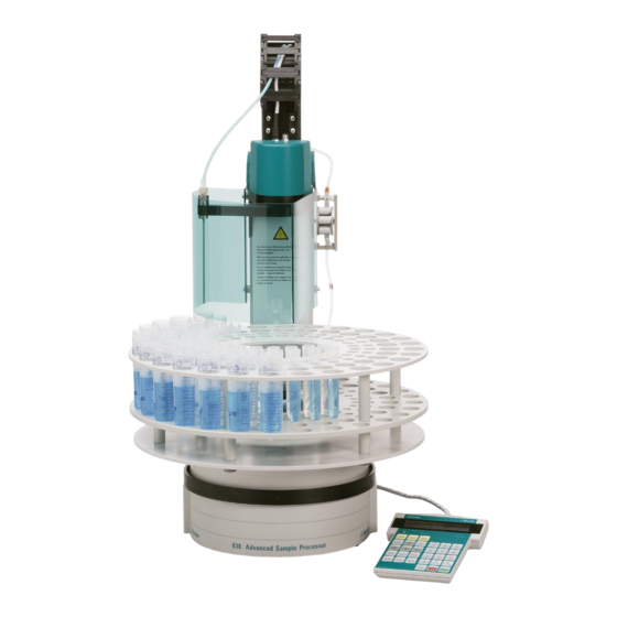
- Page 1 CH-9101 Herisau/Switzerland E-Mail info@metrohm.ch Internet www.metrohm.ch Metrohm Sample Processors 838 Advanced Sample Processor Technical Reference Program versions 5.838.0013 8.838.1133 06.2006 / dm...
-
Page 2: Table Of Contents
4 The Metrohm Remote Interface......33 Pin assignation of the Remote interface ........... 33 4.1.1 The Remote socket ................35 4.1.2 Standard allocation of remote lines in Metrohm measuring and titration instruments:....................36 4.1.3 The standard Remote lines..............37 4.1.4 Wiring of the Metrohm Standard Remote cable ........38 5 Technical specifications........ - Page 3 Contents 5.10 Stirrer connectors ..................40 5.11 Mains connection..................40 5.12 Safety specifications................... 41 5.13 Electromagnetic Compatibility (EMC) ............41 5.14 Temperatures ....................41 5.15 Dimensions and material................41 838 Advanced Sample Processor, Technical Reference...
-
Page 5: The Metrohm Remote Control Language
Language 1.1 General rules Metrohm instruments have an extensive remote control facility that al- lows full control of the instrument via the RS 232 interface, i.e. the in- strument can receive data from an external controller or send data to an external controller. -
Page 6: Call Up Of Objects
'Language' at this level: ..L n+1 preceding dots. If you must jump back to the root, enter a preceding &. Change from node 'Language' via the root to node 'Mode': &M 838 Advanced Sample Processor, Technical Reference... -
Page 7: Triggers
Querying the value of the baud rate: &Config.RSSet.Baud $Q Querying all values of the node "RSSet": &Config.RSSet $Q Querying the path of the node "RSSet": &Config.RSSet $Q.P Start mode: &Mode $G Querying the detailed status: $D 838 Advanced Sample Processor, Technical Reference... -
Page 8: Status Messages
$R.Mode.XXXX.Inac: instrument in the XXXX mode, inactive. Status conditions of the global $S: $S.Mode.XXXX.Inac: The instrument gives the status from which it has been stopped. The detailed status information is therefore identical to those of the global status $G. 838 Advanced Sample Processor, Technical Reference... -
Page 9: Error Messages
Error messages are added to the status messages and separated from them by the sign ";". This list of error messages applies to all instruments provided with the Metrohm remote control language. Incorrect program check sum RAM read/write error RAM lost data (battery) - Page 10 Exit: Correct error or &m $S. E121 Measuring point list overflow (more than 500 measuring points). Exit: The error message disappears on next startup. E122 EP overflow. Exit: The error message disappears on next startup or on recalculation. 838 Advanced Sample Processor, Technical Reference...
- Page 11 Exit. The error message disappears on next start. E158 A second TIP has been called up in TIP. Exit: The error message disappears on next start. E160 No new temporary variable. Exit: The error message disappears on next start. 838 Advanced Sample Processor, Technical Reference...
- Page 12 Measured value below lower limit. Exit: The error message disappears when again within the limits or &m $S. E185 Measured value above upper limit. Exit: The error message disappears when again within the limits or &m $S. 838 Advanced Sample Processor, Technical Reference...
- Page 13 Error list full E208 Timeout reached E209 Instrument temperature too high (>60°C) E210 Check Pt sensor E211 Short circuit on Pt 100/1000 E212 Remote-Box transfer error E213 Remote-Box keyboard timeout E214 Remote-Box, check parameter 838 Advanced Sample Processor, Technical Reference...
-
Page 14: The Remote Control Tree
The meaning of the individual object is described here in brief, for more detailed information please refer to 'Instructions for use'. The de- fault values of the objects are printed in boldface. 838 Advanced Sample Processor, Technical Reference... -
Page 15: Mode - Method Parameters
The &Mode.FinalSeq.*.Cmd node defines the command of the indexed │ command line in a final sequence. The introduction of a command appends the │ according sub-branch from &Assembly to the index node. See also the descriptions of the Start sequence. │ 838 Advanced Sample Processor, Technical Reference... - Page 16 STOP device1, .RemCtl Remote command │ STOP device2, │ STOP device*, │ 14 x 1,0 or * (bin) ├ &M;$S, 14 ASCII characters .RSCtl Command via RS232 interface ├ .Peristaltic on, off, cont. Pump state 838 Advanced Sample Processor, Technical Reference...
- Page 17 ├ .StirT2 Stirrer of tower 2 on, off, cont. ├ .StirMSB1 MSB Stirrer 1 on, off, cont. ├ .StirMSB2 MSB Stirrer 2 on, off, cont. └ .StirMSB3 MSB Stirrer 3 on, off, cont. 838 Advanced Sample Processor, Technical Reference...
-
Page 18: Configuration
0…235 mm ├ .RackDef Rack definitions │├ .RecallRack Load rack defninitions │:├ .Name Rack name 6.2041.440,..│ │ ├ .Code Rack code 010100(b)...111111(b) │ ├ .WorkT1 Working lift height at tower 1 0...235 mm 838 Advanced Sample Processor, Technical Reference... - Page 19 │ └ │ .Bytes Size of rack table read only ├ .WetPart Buret definitions │├ .WetPartNo Selection of buret unit 1...3 │ │├ Settings of port 1 │:├ .MaxRate Maximum feeding rate 0.01...160 mL/min 838 Advanced Sample Processor, Technical Reference...
- Page 20 Data bits 7; 8 ├. StopBit Stop bits 1; 2 ├. Parity Parity even; odd; none ├. Handsh Handshake HWS; SWchar; SWline; none └. CharSet External printer definition IBM; Epson; Seiko; Citizen; HP DeskJ 838 Advanced Sample Processor, Technical Reference...
-
Page 21: Info - Instrument Data
0, 801, 804, … ││├ .Rate Stirring rate 0…15 ││└ .State Stirrer status on, off │├ .MSB2 MSB stirrer 2 ││├ .Type Type of stirrer 0, 801, 804, … ││├ .Rate Stirring rate 0…15 838 Advanced Sample Processor, Technical Reference... - Page 22 Display content |├. Display line 1 24 ASCII characters |└. Display line 2 24 ASCII characters └. Counter Sequence counter ├. Sample Current sample 0…1000 └. Maximum Number of samples to be processed 0…1000 838 Advanced Sample Processor, Technical Reference...
-
Page 23: Setup - Instrument Setup
Adjustment angle of the light barrier (positive) -8.59 ││├. AngleNeg Adjustment angle of the light barrier (negative) -8.59 ││├. RotOffset Offset angle in rotational direction 0.00 ││└. Distance Axial distance (Swing head — Rack) 166.00 838 Advanced Sample Processor, Technical Reference... - Page 24 Memory initialization |└. Select Selection of the tree branch all; param; config; user meth; setup;assembly ├. RamInit Initialization of the working memory └. InstrNo Device identification └. Value Name of the device 8 ASCII characters 838 Advanced Sample Processor, Technical Reference...
-
Page 25: Usermeth - User Defined Methods
├. Name └. Checksum Remark on file operations First set the file names (node: .Name), then send the trigger $G for the corresponding function:. Example: Loading a method &U.R.N"Chloride" &U.R;$G 838 Advanced Sample Processor, Technical Reference... -
Page 26: Assembly - Instrument Components
.Address Interface selection Rm, RS │└ .Pattern Signal pattern or data string Remote interface: ∗ │ 8 x 1,0 or (binary pattern) │ Ready1, Ready2, Ready*, Cond ok, End1, End2, │ Endmeter, Continue │ 838 Advanced Sample Processor, Technical Reference... - Page 27 └ .Value Rate 0.01...160 ml/min, max. ├ .Object Rotational direction of valve disk COCKMOVE ├ .Adress Dosing drive address 1...3 │ └ .Value Direction auto, not over, desc., asc. ├ .Object Lift rate LIFTRATE 838 Advanced Sample Processor, Technical Reference...
- Page 28 Waiting time $G, $S, $H, $C │├ .Func Function PAUSE, RUNTIME │└ .Time Time 0...1...9999 s │ ├ .Beaker Beaker test │└ .Address Sensor selection Tower1, Tower2, Swing1, │ Swing2 └ .Rack Rack reset 838 Advanced Sample Processor, Technical Reference...
-
Page 29: Diagnose - Instrument Diagnosis
Rack code test ├ .FunctionTest Detailed instrument function test ├. SimulateKey Keycode simulation 1..31, see page 19 ├. Flash Write Flash-ROM ├. PowerOn 'Power on' simulation └. InstrNo Instrument number not accessible via RS232 interface 838 Advanced Sample Processor, Technical Reference... -
Page 30: Properties Of The Rs 232 Interface
3.1 Data Transfer Protocol 3 Properties of the RS 232 Interface 3.1 Data Transfer Protocol Metrohm instruments are configured as DTE (Data Terminal Equip- ment). The RS 232 interface has the following technical specifications: • Data interface according to the RS 232C standard, adjustable transfer parameters, see pages 14ff. -
Page 31: Handshake
Metrohm instrument as Sender : Metrohm instrument external device XOFF Data Data input Data output Data output max. disabled enabled characters Time max. characters: 2 characters at 300...9600 baud 16 characters at ≥ 19200 baud 838 Advanced Sample Processor, Technical Reference... - Page 32 The instrument's transmission can be stopped by external instruments with XOFF. After XOFF is received the instrument completes sending the line already started. If data output is disabled for more than 10 s by XOFF, E43 appears in the display. 838 Advanced Sample Processor, Technical Reference...
- Page 33 3.2 Handshake Hardware-Handshake, HWs Metrohm instrument as Receiver : Metrohm instrument external device Time Metrohm instrument as Sender: Metrohm instrument external device Time The data flow can be interrupted by deactivating the CTS line. 838 Advanced Sample Processor, Technical Reference...
-
Page 34: Pin Assignment
(CTS, RTS, DTR) voltage negative (<-3 V): OFF state voltage positive (>+3 V): ON state In the transitional range from +3 V to -3 V the signal state is undefined. 838 Advanced Sample Processor, Technical Reference... - Page 35 Driver 14C88 according to EIA RS 232C specification Receiver 14C89 " " Contact arrangement at plug (female) for RS 232C socket (male) No liability whatsoever will be accepted for damage or injury caused by improper interconnection of instruments. 838 Advanced Sample Processor, Technical Reference...
-
Page 36: What Can You Do If Data Transfer Fails
Is your cable correctly wired? (The DTR of the printer has to be connected to the CTS of the instrument.) Set "HWs" for the handshake of the instrument. Configure the printer such that its DTR is set (possibly with DIP switches). 838 Advanced Sample Processor, Technical Reference... -
Page 37: The Metrohm Remote Interface
STOP *, End2 +5 V pin 12 (Input 7) external START * * if external START on Voltage I ≤ 200 mA pin 15 +5 V pin 14 0 V: active 5 V: inactive pin 25 838 Advanced Sample Processor, Technical Reference... - Page 38 All outputs may be freely set by the CTRL command. Ordering number for standard Remote cable: 6.2141.020, see Metrohm Accessories Catalog also. No liability whatsoever will be accepted for damage caused by im- proper interconnection of instruments. 838 Advanced Sample Processor, Technical Reference...
-
Page 39: The Remote Socket
Input 4 Input 5 active = low Input 6 Input 7 0 Vo lt inactive = high Output 11 Remote plug Electrical switching of the inputs (with 25 pins) and outputs of the remote socket 838 Advanced Sample Processor, Technical Reference... -
Page 40: Standard Allocation Of Remote Lines In Metrohm Measuring And Titration Instruments
4.1 Pin assignation of the Remote interface 4.1.2 Standard allocation of remote lines in Metrohm measuring and titration instruments: Remote lines Function Input 0 Start Input 1 Stop Input 2 Enter Input 3 Clear Input 4 Sample Ready Input 5... -
Page 41: The Standard Remote Lines
0 Volt Sample Processors only The pin assignation or the allocation of functions of the remote lines may differ slightly from one Metrohm instrument to another. Consult the ‘Instructions for use’ of your instrument. 838 Advanced Sample Processor, Technical Reference... -
Page 42: Wiring Of The Metrohm Standard Remote Cable
4.1 Pin assignation of the Remote interface 4.1.4 Wiring of the Metrohm Standard Remote cable Order no. 6.2141.020 (25-pin) Output 0 (Pin 5) (Pin 21) Input 0 Output 1 (Pin 18) (Pin 9) Input 1 Output 2 (Pin 4) (Pin 22) Input 2... -
Page 43: Technical Specifications
±15 steps Delivery rate (typical) Tubing Delivery (with water, no back- 6.1826.010: 1.4 ml/min pressure, dependent 6.1826.020: 3.8 ml/min on contact pressure 6.1826.030: 0.4 ml/min and tubing type, at 6.1826.040: 0.8 ml/min 838 Advanced Sample Processor, Technical Reference... -
Page 44: Pump Connectors
15 levels Stirring speed 741 Magnetic stirrer 180/min...2600/min 802 / 722 Rod stirrer 180/min...3000/min 5.11 Mains connection Voltage 100… 240 V (±10%) Frequency 50...60 Hz Power input 115 W Fuse 2.0 ATH 838 Advanced Sample Processor, Technical Reference... - Page 45 < +50 °C < 85% humidity < +60 °C < 50% 5.15 Dimensions and material 0.73 m Height 0.28 m Width 0.50 m Depth 15.50 kg (1.838.0010) Weight 15.90 kg (1.838.0020) (not including accesso- ries) 838 Advanced Sample Processor, Technical Reference...
- Page 46 5.15 Dimensions and material Materials - Sample changer Metal housing, surface-treated housing - Keypad housing Crastin (PBTB), aluminium-sputtered on inside - Keypad film Polyester, chemical-resistant 838 Advanced Sample Processor, Technical Reference...
Need help?
Do you have a question about the 838 and is the answer not in the manual?
Questions and answers