
Related Manuals for Emerson Rosemount 3490 Series


Summary of Contents for Emerson Rosemount 3490 Series
- Page 1 Reference Manual 00809-0100-4841, Rev CA January 2021 ™ Rosemount 3490 Series ® 4-20 mA + HART Compatible Controller...
- Page 2 Outside of these areas, contact your local Emerson representative. WARNING Replacement equipment or spare parts not approved by Emerson for use as spare parts could reduce the capabilities of the Rosemount 3490 Series Control Unit, and may render the instrument dangerous.
- Page 3 The products described in this document are NOT designed for nuclear-qualified applications. Using non-nuclear qualified products in applications that require nuclear-qualified hardware or products may cause inaccurate readings. For information on Rosemount nuclear-qualified products, contact your local Emerson Sales Representative.
-
Page 5: Table Of Contents
A.4 Mechanical..........................150 A.5 Environment..........................151 A.6 Dimensional drawings......................153 A.7 Rosemount 3491, 3492, and 3492 ordering information............156 A.8 Accessory..........................157 Appendix B Product certifications.....................159 B.1 European Union directive information..................159 B.2 Installing equipment in North America..................159 B.3 North America......................... 159 Emerson.com/Rosemount... - Page 6 Menus and parameter.................... 165 Appendix D Additional features....................181 D.1 Restoring the factory defaults....................181 D.2 Advanced parameter access....................181 ® Appendix E Support for HART Transmitters................185 E.1 Overview..........................185 E.2 Fully supported HART transmitters..................185 E.3 Generic support for HART transmitters..................185 Emerson.com/Rosemount...
-
Page 7: Chapter 1 Introduction
Rosemount 3493 Logging Control Unit The software release covered in this product manual is issue 4.00.00 (and above). Product recycling/disposal Recycling of equipment and packaging should be taken into consideration and disposed of in accordance with local and national legislation or regulations. Emerson.com/Rosemount... - Page 8 Introduction Reference Manual January 2021 00809-0100-4841 Emerson.com/Rosemount...
-
Page 9: Control Unit Overview
• The Rosemount 3492 Differential Control Unit accepts two HART transmitter inputs. Note The Rosemount 3490 Series is designed for non hazardous (safe) area installation, but can be connected to a transmitter installed in a hazardous area. Related information Product certifications... -
Page 10: Control Unit Functions
B. Rosemount 3490 Series Control Unit C. 4–20 mA signal output D. Relay E. Pump F. Bottom reference G. 4–20 mA and HART signal Control unit functions 2.2.1 Standard functions The Rosemount 3490 Series Control Unit (“control unit”) provides these standard functions: Emerson.com/Rosemount... - Page 11 HART transmitters. 2.2.3 Data logging functions The Rosemount 3493 Logging control unit has all the functions of the standard control unit, plus a 7000 event logging function. Emerson.com/Rosemount...
-
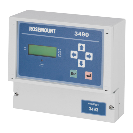
Page 12: Control Unit Front Panel
When navigating the menu system, use the escape button to return to a previous menu level and the Full PV display. At other times, e.g. while editing, the button is for restoring a setting that is being edited. Emerson.com/Rosemount... - Page 13 On the Rosemount 3492, an extra icon on the first line and indicates if one or two HART transmitters connected to the control unit. • On the Rosemount 3493, there are two totalizers displayed; one above and one below the control unit PV. Emerson.com/Rosemount...
- Page 14 Display. This shows only the control unit PV and display units, but in a larger character size to facilitate easier viewing. Procedure To restore the Full PV Display, press the red (enter) button. Note The Large PV Display feature can be switched off using parameter P574. Emerson.com/Rosemount...
- Page 15 Reference Manual Control unit overview 00809-0100-4841 January 2021 Figure 2-5: Display Views 1. 572 m 12:47 1. 572 m A. Large PV Display B. Full PV Display Related information Display configuration options Emerson.com/Rosemount...
- Page 16 Control unit overview Reference Manual January 2021 00809-0100-4841 Emerson.com/Rosemount...
-
Page 17: Chapter 3 Installation
Considerations before installation 3.2.1 Safety considerations Note The Rosemount 3490 Series is designed for non-hazardous (safe) area installation, but can power and take input from an intrinsically safe transmitter installed in a hazardous area. Guidelines 1. This product is classified type A in accordance with European EMC directive 2014/30/EU. - Page 18 The shield should be left unconnected at the transmitter unless there is a terminal specifically provided for this purpose. 11. Cable runs should be separate from any high voltage or mains cables to avoid crosstalk or interference. Related information Product certifications Specifications and reference data Emerson.com/Rosemount...
- Page 19 Ensuring there is enough clearance behind the chosen position in the panel (6.5- in./165 mm minimum), cut a horizontal slot 5.43-in. (138 mm) long by 2.68-in. (68 mm) high in the panel and remove any rough edges. Related information Accessory Emerson.com/Rosemount...
- Page 20 • Do not mount the control unit on a structure that is subject to vibration, or in a position where damage may be caused by impact, thermal stress, or liquid ingress. Emerson.com/Rosemount...
-
Page 21: Mounting The Control Unit
(see Figure 3-4) and see how the four steel lugs (protrusions) of the screw clamp frame engage with the lugs of the control unit. Gently pull the screw clamp for the lugs to engage with each other. Emerson.com/Rosemount... - Page 22 Making electrical connections on panel-mount units 3.3.2 Mounting the IP-rated wall mount version Procedure 1. Mount the unit on a suitable wall or structure using the fixing points. 2. Make the electrical connections. Related information Installation guidelines for the IP-rated wall mount version Emerson.com/Rosemount...
-
Page 23: Electrical Installation
IP-rated version and by four screws on the NEMA 4X rated version. The cabling between the Rosemount 3490 Series Control Unit (“control unit”) and a transmitter should be a screened (shielded), twisted-pair type with the cable screen... - Page 24 1 and 2 is in a hazardous area Note In intrinsically safe systems, apparatus connected to the Rosemount 3490 Series Control Unit must not be supplied from a voltage greater than 250 V r.m.s. or 250 Vdc.
- Page 25 The white sealing washers (supplied in the plastic bag) must be fitted on the outside of the enclosure under the blanking plugs. Related information RS232 connections Cable gland and conduits for the NEMA 4X-rated wall-mount unit The Rosemount 3493 Control Unit has a data download socket factory pre-fitted. Emerson.com/Rosemount...
- Page 26 Installation Reference Manual January 2021 00809-0100-4841 Refer to the Rosemount 3490 Series Quick Start Guide for information about where holes can be drilled for fitting cable glands. Related information RS232 connections 3.4.2 Making electrical connections on panel-mount units Field wiring connections are made to the back of the panel-mount control unit using the two-part (plug/socket) terminal connectors provided.
- Page 27 When the control unit is direct current (dc) powered, ensure the supply is adequate (15 to 30 Vdc). Do not exceed 30 Vdc. A switch or circuit breaker should be installed in close proximity to the instrument, and labeled as such. Although the Rosemount 3490 Series Control Unit meets all European Emerson.com/Rosemount...
- Page 28 3.4.4 Earthing connections The IP-rated Rosemount 3490 Series Control Unit is double insulated and does not require a mains earth. Note Do not connect terminal 30 to a mains earth. Terminal 30 is provided for use as an intrinsically safe (or functional) earth connection, which must be used when a transmitter is mounted in a hazardous area and is connected to terminals 1 and 2.
- Page 29 The control unit supplies 23 Vdc from a 400 Ohm source to power transmitters. Separately powered transmitters must be connected to terminals 2 and 3 (see Figure 3-8). Figure 3-8: Self-powered Transmitter Connections 24 V A. Control unit B. Transmitter Emerson.com/Rosemount...
- Page 30 With the power supply turned off, connect the first HART transmitter to the Current Input terminals on the control unit. 2. Check the voltage-selector-switch is set for the correct voltage on the mains- powered control unit (115 or 230 Vac), and then turn the power on. Emerson.com/Rosemount...
- Page 31 Transmitter Bottom Reference can be changed later, but it is better to get it correct now. The two HART transmitters are now known to the control unit, and will be remembered each time the power is switched off and on. Emerson.com/Rosemount...
- Page 32 3-11. In loop-powered mode, an external power source is required. A minimum of 2.5 Vdc is required across terminals 7 and 8 for correct operation. The voltage must not exceed 30 Vdc. Figure 3-10: Internally-powered A. Load Figure 3-11: Loop-powered A. Load B. External supply Emerson.com/Rosemount...
- Page 33 4, 5, and 6 on the rear of the control unit. Procedure 1. Cut-out the hole in the panel. Figure 3-13: Panel Cut-out (RS232 Data Download Socket) 0.13 (3.2) 0.47(11.85) Ø0.81 (Ø20.5) Dimensions are in inches (millimeters). Emerson.com/Rosemount...
- Page 34 3. Use the supplied mini-B nut to secure the socket to the panel. 4. Wire the socket flying lead to terminals 4, 5, and 6 (panel mount unit) A. 4: Rx (white) B. 5: Tx (red) C. 6: 0V (black) Emerson.com/Rosemount...
- Page 35 Reference Manual Installation 00809-0100-4841 January 2021 5. Connect the RS232 data-download cable. See the Rosemount 3493 LogView Reference Manual for further information on downloading logged data. Emerson.com/Rosemount...
- Page 36 Installation Reference Manual January 2021 00809-0100-4841 Emerson.com/Rosemount...
-
Page 37: Chapter 4 Getting Started
This is optional, and selecting the red (enter) button continues the start-up process. At this time, the control unit reads parameters from the HART transmitter and makes them available for local interrogation and programming within the control unit menu system. Emerson.com/Rosemount... - Page 38 The Transmitter Bottom Reference can be changed later, but it is better to get it correct now. Procedure 1. Press the red (enter) button. Re-connecting to Digital Transmitter Please Wait Bottom Reference = distance to sensor from tank bottom = Continue Emerson.com/Rosemount...
- Page 39 5. Do one of the following: Bottom Reference saved. Setuo controller ? ESC=No =Yes • Press the red (enter) button to enter the Controller SETUP menu – Use App Wizard. • Press the Esc button to enter the MAIN MENU. Related information Application wizard Emerson.com/Rosemount...
- Page 40 (Tx1). This configuration can be changed to show the sum, difference or product of the readings from both transmitters. Figure 4-2: The Rosemount 3492 Control Unit with Two HART Transmitters A. Rosemount 3490 Series Control Unit B. Rosemount 3102 or 3105 Transmitter C. HART communications D.
-
Page 41: Main Menu
An ↑ symbol indicates there are further menu options available, accessible by using the up arrow button. The MAIN MENU sits above a series of sub-menus, which lead to further levels of sub-menus that lead to parameter screens (see Figure 4-3). Emerson.com/Rosemount... - Page 42 E. Selecting Tx1: **** leads to menus for viewing live readings and diagnostic information from the HART transmitter Tx1 (and similarly for Tx2 on the Rosemount 3492). F. Advanced access menu for advanced users to directly select parameter screens when the parameter number is known. Emerson.com/Rosemount...
- Page 43 TOTALIZER, PV DAMPING, ALARM, and FAULT. 6. Explore these menu options to see screens for setting-up for an application and for displaying read-only information. 7. After exploring, hold down the Esc button once to return to the MAIN MENU. Related information Additional features Emerson.com/Rosemount...
-
Page 44: Programming Using The Front Panel
00809-0100-4841 Programming using the front panel This section covers programming using the front panel of the Rosemount 3490 Series Control Unit (“control unit”) to make changes to the factory default set-up. Use the Application Wizard (“App Wizard”) to easily set-up the control unit for a level, flow, or contents volume application, and then optionally adjust the set-up by editing parameters in the menu system. - Page 45 4, Edit has changed to be Save. Up Range Val P401 12.000 m Esc =Quit =Save Parameter is in Edit Mode. In this mode, selecting Esc button restores the original setting and returns to View Mode. 3. Change the number from “+12.000” to “+6.500”. Emerson.com/Rosemount...
- Page 46 62.000 m Esc =Quit =Save d) Press the down arrow button three times to change the “2” to a decimal point. Up Range Val P401 62.000 m Esc =Quit =Save Up Range Val P401 .000 m Esc =Quit =Save Emerson.com/Rosemount...
- Page 47 6.5000 m Esc =Quit =Edit (Note that on display line 4, Save has changed back to Edit). Parameter has returned to View Mode. 5. Press the Esc button to return to the SETTINGS menu. Related information Enter the menu system Emerson.com/Rosemount...
- Page 48 2. To enter Edit Mode, press the red (enter) button. Date P730 30/01/14dmy Esc =Quit =Edit Date P730 30/01/14dmy Esc =Quit =Save The “3” is highlighted to show this digit can now be edited. Also, note that on display line 4, Edit has changed to be Save. Emerson.com/Rosemount...
- Page 49 31/01/14dmy Esc =Quit =Save Date P730 31/01/14dmy Esc =Quit =Edit Note that on display line 4, Save has changed back to Edit. 5. Press the Esc button to return to the SETTINGS menu. Related information Enter the menu system Emerson.com/Rosemount...
- Page 50 When no HART transmitters are used, the SELECT INSTRUMENT screen does not appear. As there is no need to select the control unit menu or a HART transmitter (Tx1 or Tx2) menu, the menus that appear after selecting MAIN MENU → SETUP are purely for the control unit. Emerson.com/Rosemount...
-
Page 51: Programming Of The Control Unit
Change application settings (advanced users) • Change the digital input settings • Change output settings • Set-up other features 4. Put the unit into Run App mode. Related information Change the operating mode Application wizard Optional changes after using the App Wizard Emerson.com/Rosemount... - Page 52 Outputs are frozen unless allocated to totalizing and sampler duties. Fault relays are de-energized. Figure 4-6: Switching to Run App Mode MAIN MENU SETUP Run App? Run App? MONITOR Run App? = Yes Esc=No MAIN MENU SETUP SETUP Program? MONITOR Emerson.com/Rosemount...
- Page 53 Reference Manual Getting started 00809-0100-4841 January 2021 Figure 4-7: Switching to Program Mode MAIN MENU SETUP Run App? Program? MONITOR Program? = Yes Esc=No MAIN MENU SETUP SETUP Program? MONITOR Emerson.com/Rosemount...
- Page 54 • Relay 1 (Pump 1) on at 5 ft.; off at 1 ft. • Relay 2 (Pump 2) on at 8 ft.; off at 1 ft. • Relay 3 (High Alarm) on at 12 ft.; off at 11 ft. Emerson.com/Rosemount...
- Page 55 D. Options: Number of starts, Run-Time, Ratio of Run-Time, Ratio of starts E. Options: Relay(s), Pump Control, Custom F. Options: Set point, Hi or Lo Alarm, Rate of change, Out of limits, Digital input G. Exits to menu system. (Select Run App mode to start application.) Emerson.com/Rosemount...
- Page 56 Tank dimensions are 6.5 ft. dia. x 25 ft. length. • Volume capacity is 6205.6 gallons. Outputs: • Contents volume in US gallons displayed. • Relay on at 6000 gallons; off at 5800 gallons. • Current Output range 0 to 6200 gallons. Emerson.com/Rosemount...
- Page 57 E. Options: Relay(s), Pump Control, Custom F. Options: Relay 1, Relay 2, Relay 3, Relay 4 G. Options: Set point, Hi or Lo Alarm, Rate of change, Out of limits, Digital input H. Exits to menu system. (Select Run App mode to start application.) Emerson.com/Rosemount...
- Page 58 Open channel is a 60° V-Notch Weir. • Maximum flow is 645.50 gallons per minute. • Height at maximum flow is 1 ft. Outputs: • Flow rate in gallons per minute. • Totalized flow in gallons x 100. • 2% low flow cut-off. Emerson.com/Rosemount...
- Page 59 F. Options: gallons, gallons x10, gallons x100, gallons x1000, million gallons, cubic feet G. Exits to menu system. (Select Run App mode to start application.) 4.4.3 Optional changes after using the App Wizard Change system settings This includes how to switch on the keyboard sound, setting the date/time, and changing language. Emerson.com/Rosemount...
- Page 60 By default, security restrictions are switched off and the user has access to all parameters. After programming (configuring) is complete, a PIN security code can be used to prevent unauthorized access. Related information Data logging on the Rosemount 3493 Set-up alarms Emerson.com/Rosemount...
- Page 61 HART transmitter. There is one transmitter input channel and it is referred to as Input Channel 1. For a 4–20 mA transmitter, see: • Programming Input Channel 1 for a 4–20 mA input (advanced users) For a HART transmitter, see: • Programming Channel 1 for a HART input (advanced users) Emerson.com/Rosemount...
- Page 62 2. Set Input Channel 1 to receive input from a 4–20 mA transmitter. a) Navigate to the menu SETUP → [CONTROLLER] → INPUT CHANNEL → Ch1 I/P Source for the Ch1 I/P Source parameter P111. b) Select mA in 1 from the option list. Emerson.com/Rosemount...
- Page 63 Proceed with configuration of optional parameters. Optional parameters and how the 4-20 mA signal is processed Figure 4-11 shows how the 4–20 mA input signal is processed through Input Channel 1 and which parameters and processing stages affect the resulting control unit PV. Emerson.com/Rosemount...
- Page 64 Conversion of signal into a percentage value By default, the mA signal (readable via D840) is converted (normalized) into a percentage in the range 0 to 100% (readable via D842), where 4 mA is 0% and 20 mA is 100%. Emerson.com/Rosemount...
- Page 65 Note P117 is in the menu SETUP → [CONTROLLER] → INPUT CHANNEL → Ch1 Low Cut-off. Applying optional damping to the control unit PV P210 allows the to smooth out large steps in calculated values (D851). Emerson.com/Rosemount...
- Page 66 Proceed with configuration of optional parameters. Optional parameters and how the HART data is processed Figure 4-12 shows how the HART data is processed through Input Channel 1 and shows which parameters and processing stages affect the result from Input Channel 1. Emerson.com/Rosemount...
- Page 67 The HART transmitter digitally communicates pre-calculated values of four HART variables Primary Variable (PV), Secondary Variable (SV), Tertiary Variable (TV), and Fourth Variable (FV) to the Rosemount 3490 Series Control Unit. Selection of a HART variable as source for further processing Parameter P111 selects one of the four HART variables (PV, SV, TV, or FV) on the transmitter to be the source for further processing to get a result from Input Channel 1.
- Page 68 3492 and advanced users only) Procedure Set Input Channel 2 to receive HART digital data from a transmitter. a) Navigate to SETUP → [CONTROLLER] → INPUT CHANNEL → CHANNEL 2 → Ch2 I/P Source for the Ch2 I/P Source parameter P121. Emerson.com/Rosemount...
- Page 69 ((D800now - D800before)/(1+10 × P210))] HART digital data is continuously read from the transmitter The HART transmitter digitally communicates pre-calculated values of four HART variables Primary Variable (PV), Secondary Variable (SV), Tertiary Variable (TV), and Fourth Variable (FV) to the control unit. Emerson.com/Rosemount...
- Page 70 P127 is in this menu SETUP → CONTROLLER → PV CALCULATION → CHANNEL 2 → Ch2 Low Cut-off. Applying optional damping to the control unit PV P210 is used to apply damping to smooth out big steps in calculated values in D852. Emerson.com/Rosemount...
- Page 71 D851 = (P114 × Level measurement after offset P112 is applied) For a HART level transmitter measuring level for Input Channel 2, the volume is calculated as: D852 = (P124 × Level measurement after offset P122 is applied) Emerson.com/Rosemount...
- Page 72 Popular non-linear (non-uniform) vessel applications Figure 4-14: Horizontal Cylinder, Flat Ends, Slope Ignored P113/P123 = Horiz Cyl Flat P114/P124 = (1.0 / Diameter of tank) P115/P125 = Plotted non-linear profile of tank P116/P126 = Full volume of ideal cylindrical tank Emerson.com/Rosemount...
- Page 73 The non-linear profile (NLP) is plotted automatically when editing P113/P123 manually or when using the Application (App) Wizard, except for the Conical NLP. Menu: SETUP → [CONTROLLER] → APPLICATION → App Wizard P115/P125 is plotted with a simple cone if P113/P123 is set to Conical manually. Emerson.com/Rosemount...
- Page 74 The level measurement, after any input offset has been applied, must be re-scaled to the range 0.0 to 1.0 ready for input to the NLP calculation. For example, if the level measurement range is 0.0 to 4.0, set P114 = (1.0/4.0) = 0.25 Emerson.com/Rosemount...
- Page 75 Set-up flow calculations for non-linear/non-uniform open channel profiles (advanced users) The Rosemount 3490 Series Control Unit can use level measurements to calculate flow in open channels, which can then be totalized. The control unit has a library of popular non- linear profiles for flow: •...
- Page 76 P116 = Maximum flow at maximum flow height Essential parameters to program Note P200 (PV units) must be changed from % to the required units of measurement. The parameter P200 is in the menu SETUP → [CONTROLLER] → DISPLAY. Emerson.com/Rosemount...
- Page 77 The control unit Primary/Process Value (D800) for the flow rate is derived by applying the normalized transmitter input (range 0.0 to 1.0) to the profile, and then converting (scaling) by parameters P114 and P116 (or P124 and P126). Emerson.com/Rosemount...
- Page 78 Set-up open channel flow calculations for pre-programmed flat, parabolic, and Parshall flumes (advanced users) The Rosemount 3490 Series Control Unit (“control unit”) has a library of data to set-up open channel flow calculations with flat, parabolic, and Parshall flumes. Related information...
- Page 79 Terms mul is 1.000 and pwr is 1.5 for a rectangular weir. Therefore, k is calculated as Q/(mul × Input) ) = 2000/(1 × 0.792) = 2837.5 Note Flow calculations require the transmitter input channel(s) to be providing continuous level measurements. Also, P200 (control unit PV units) must be changed. Emerson.com/Rosemount...
- Page 80 Flume Para 7 0.77152 0.01 3600.0 Flume*** (User) (User) (User) 3600.0 Note Vlarem flumes most commonly are used for open channel flow applications in Belgium. When selecting a Vlarem flume from the above list, the PV flow units are automatically set Emerson.com/Rosemount...
- Page 81 These X points may be entered as levels (in the same units as the transmitter) and the Y points entered as the corresponding volumes or flow rates for those levels (in the same units as selected for the control unit Primary/Process Value). See Figure 4-18, right-hand graph. Emerson.com/Rosemount...
- Page 82 P123 to P126 are in the menus SETUP → CONTROLLER → PV CALCULATION → CHANNEL 2 → Ch2 Profile, Ch1 Pre scale, Ch2 NLP Data, and Ch2 Post Scale. Edit the 'look-up' table (P115/P125) Prerequisites Parameter P113/P123 must first be set to be “Special”. Procedure 1. Navigate to the P115/P125 parameter screen. Emerson.com/Rosemount...
- Page 83 Digital input IN1 and IN2 statuses are shown on the left-hand side of the display: o = inactive or ▸= active. Parameter D835 shows the statuses of the inputs: active (1) or inactive (0). First digit represents IN1. The second digit represents IN2. Emerson.com/Rosemount...
- Page 84 Totalizer 2 is available on the Rosemount 3492 and Rosemount 3493. 3. Use the delay parameter P341 (for IN1) or P346 (for IN2) if a delay is needed before an action is performed. The setting format is m:s (minutes and seconds). Emerson.com/Rosemount...
- Page 85 “LOG” in the bottom, right-hand corner of the Full PV display. Note Logged data may be downloaded at any time using the RS232 data download socket, supplied with a Rosemount 3493, and Rosemount LOG-VIEW software running on a Windows PC. Emerson.com/Rosemount...
- Page 86 Parameter D846 shows the percentage of free memory remaining for data logging. Related information Data logging screens Starting, stopping and resetting the logger Using the logging wizard for data logging of level measurements Using the logging wizard for data logging of flow measurements Emerson.com/Rosemount...
- Page 87 MONITOR SELECT INSTRUMENT Controller: **** Tx1: **** SETUP DISPLAY OUTPUT LOGGING LOGGING Logging Wizard Log Interval Fast Log Log Interval P590 0 min Esc =Quit =Edit The SELECT INSTRUMENT menu does not appear unless a HART transmitter is connected. Emerson.com/Rosemount...
- Page 88 Logging Wizard ESC =Quit =Start 2. Start the Logging Wizard by selecting the red (enter) button once. 3. Change the operating mode to Program, if prompted. 4. Work through the wizard prompts (Figure 4-20) until the menu system re-appears. Emerson.com/Rosemount...
- Page 89 PV is a flow measurement in cubic meters per second. When the flow measurement is at 1 cubic meter per second or more, the Fast Log mode is required to activate. When the memory is at 90% of capacity, a relay is activated instead of overwriting old data. Emerson.com/Rosemount...
- Page 90 LOG Digital input ( s ) None A. Measurement units for this wizard are dependent on control unit PV display units selected using P200. B. Options: Yes, No C. Options: None, Relay, Current, Both D. Options: 1, 2, 3, 4 Emerson.com/Rosemount...
- Page 91 10 meters is represented by 20 mA signal (100%) Therefore, the Current Output would output the PV value five meters as a 12 mA signal. Note The current output is frozen while the control unit is in the program operating mode. Emerson.com/Rosemount...
- Page 92 P590, which is also for setting the logging interval. P210 MCU PV This is used to apply damping to smooth out big Damping steps in calculated control unit Primary/Process values (PV). Related information Control unit reporting of alarms and faults Data logging on the Rosemount 3493 Emerson.com/Rosemount...
- Page 93 Run App? SELECT INSTRUMENT MONITOR Controller: **** Tx1: **** SETUP APPLICATION DISPLAY OUTPUT OUTPUT CURRENT OUTPUT RELAY RELAY TOTALIZER Relay Wizard Reset RL Params RELAY 1 The SELECT INSTRUMENT menu does not appear unless a HART transmitter is connected. Emerson.com/Rosemount...
- Page 94 SETUP → [CONTROLLER] → OUTPUT → RELAY → RELAY 1, RELAY 2, etc. Menu Note Relays are frozen while the control unit is in Program mode, preventing all relay operations apart from Totalizer and Sampler relays. Relay outputs 1 to 4 can be programmed to be an On/Off Point control relay. Emerson.com/Rosemount...
- Page 95 On point and de-energizes when the PV value rises above the Off Point. There are set point relays modes for the control unit SV value (D801), TV value (D802) and FV value (D803). Related information Optional change: transmitter input channel settings (advanced users) Emerson.com/Rosemount...
- Page 96 Relay energizes while Digital Input 1 (IN1) is active. Digital Input 2 Relay energizes while Digital Input 2 (IN2) is active. Sampler Relay outputs sampler pulses. Relay is energized if the rate of change of the control unit PV is out-of-limits. Emerson.com/Rosemount...
- Page 97 Relay energizes while control unit PV value (D800) is within on/off point limits. Relay is always energized. Auxiliary functions for relay modes Relay modes automatically enable and disable special control functions, special alarms and pumped volume totalizing as shown in Table 4-10 Table 4-11. Emerson.com/Rosemount...
- Page 98 Set point (PV) Set Point (SV) Set Point (TV) Set Point (FV) Assist Stby Com-off Stby Split-off Digital Inputs Sampler Rate change Alarm Hi/Lo Alarm Totalizer Fault Custom PV Limits Option available on the Rosemount 3491 and 3492 only. Emerson.com/Rosemount...
- Page 99 The control unit PV value (D800) is a level measurement in meters (m). Figure 4-22, both Pump 1 and Pump 2 are off because the liquid level is at a satisfactory level, below 5 m. Emerson.com/Rosemount...
- Page 100 F. Pump 2 If the level continues to rise and is above 8 m (On point, P421), relay RL2 is energized to start Pump 2 and assist Pump 1. Relay RL1 stays energized to keep Pump 1 pumping (Figure 4-24). Emerson.com/Rosemount...
- Page 101 D. 2.0 m (P412) E. Pump 1 F. Pump 2 In this emptying application, the common off point is P412 (Off point, relay RL1) and P422 (Off point, relay RL2), both of which are at the 2 m level. Emerson.com/Rosemount...
- Page 102 B. 8.0 m (P421) C. 5.0 m (P411) D. 3.5 m (P422) E. 2.0 m (P412) F. Pump 1 G. Pump 2 When the level exceeds 5 m (On Point, P411), relay RL1 is energized to start Pump 1 (Figure 4-27). Emerson.com/Rosemount...
- Page 103 C. 5.0 m (P411) D. 3.5 m (P422) E. 2.0 m (P412) F. Pump 1 G. Pump 2 When the level falls to below 3.5 m (Off point, P422), relay RL2 de-energizes to switch off Pump 2 (Figure 4-29). Emerson.com/Rosemount...
- Page 104 The control unit PV value (D800) is a liquid level measurement in meters (m). Figure 4-30, both Pump 1 and Pump 2 are off because the liquid level is at a satisfactory level, below 5 m. Emerson.com/Rosemount...
- Page 105 E. Pump 1 F. Pump 2 If the level continues to rise and is above 8 m (On point, P421), the relay RL2 is energized to start Pump 2. Relay RL1 is de-energized to switch off Pump 1 (Figure 4-32). Emerson.com/Rosemount...
- Page 106 Consider an application with two relays, RL1 and RL2, connected to individual pumps in a wet well. The control unit PV value (D800) is a liquid level measurement in meters. Figure 4-33, both Pump 1 and Pump 2 are off because the liquid level is at a satisfactory level, below 5 m. Emerson.com/Rosemount...
- Page 107 C. 5.0 m (P411) D. 2.0 m (P412) E. Pump 1 F. Pump 2 When the level exceeds 8 m (On Point, P421), relay RL2 is energized to start Pump 2. Relay RL1 is de-energized to switch off Pump 1 (Figure 4-35). Emerson.com/Rosemount...
- Page 108 In this emptying application, the switch off point for Pump 2 is 5 m; the On Point for relay 1 P411 (On point, relay RL1) is used. P422 (Off point, relay RL2) is ignored. When the level falls below 2 m (Off point, P412), relay RL1 de-energizes to switch off Pump Emerson.com/Rosemount...
- Page 109 For example, a value of 100 means that the Sampler relay outputs a single pulse for every 100 increment to the Totalizer Count (D828/D829) The pulse width is the same as selected for the Totalizer relay (P534) Related information Set-up totalizing Emerson.com/Rosemount...
- Page 110 SETUP → [CONTROLLER] → OUTPUT → RELAY → RELAY 1, RELAY 2, etc. and Menu MONITOR → [CONTROLLER] → READINGS → Rate of Change A rate of change value for the control unit PV value (D800) is calculated every 5 seconds in units of PV per minute: Emerson.com/Rosemount...
- Page 111 Auto Seq Enable Select a rotation auto-sequence. All options are summarized in Table 4-17. P271 Auto Seq Qual This defines the threshold (e.g. how many starts) before applying an auto-sequence to rotate the 'lead' to the next relay with the same mode. Emerson.com/Rosemount...
- Page 112 Each digit represents a relay. Relay RL1 is selected by editing the first digit to be a “1”. Similarly, relay RL5 is selected with the fifth digit. To de-select a relay, change the appropriate digit back to a “0”. Related information Auxiliary functions for relay modes Emerson.com/Rosemount...
- Page 113 For details on configuring a digital input to initiate a pump-down operation, see Digital inputs IN1 and IN2. The relay mode must be Set point, Assist or, Standby, and parameters P272 to P274 edited to set-up the pump down operation. Emerson.com/Rosemount...
- Page 114 For example, this function may be used to provide a low flow cut-off for a pump control if the pump is provided with a flow/no-flow switch. A second relay contact assigned to pump control would then be wired in series with the Custom mode relay to provide the low flow cut-off. Emerson.com/Rosemount...
- Page 115 Ext Trig Xs When a Digital Input is active, de-energize a Custom mode relay after X seconds delay. This does not require Digital Input IN1 or IN2 to be allocated an action. Abbreviations: “Ext Trig” = External Trigger (Digital Input). Emerson.com/Rosemount...
- Page 116 P494 RL run rly sel Select the relay for the monitoring operation Disabled associated with parameter P493. Note For any of the alarms below to be indicated by a relay or current output, an indication method must be selected. Emerson.com/Rosemount...
- Page 117 Each digit represents a relay. Relay RL1 is selected for monitoring by editing the first digit to be a “1”. Similarly, relay RL5 is selected with the fifth digit. To de-select a relay, change the appropriate digit back to a “0”. Related information Auxiliary functions for relay modes Emerson.com/Rosemount...
- Page 118 Pump efficiency alarm (Rosemount 3491 and 3492 only) Menu SETUP → [CONTROLLER] → APPLICATION → ALARM The pump efficiency feature allows an alarm to be indicated (P550, P4*1) if the calculated pump efficiency falls below a defined limit (P495). Emerson.com/Rosemount...
- Page 119 Relay or Current Output, a method must be selected. Note The alarm condition is automatically cleared if the calculated PE rises above the limit (P495) by 5% or more. Related information Auxiliary functions for relay modes Rate of change mode relay Emerson.com/Rosemount...
- Page 120 Total units Pumped volume totalizing is enabled by the totalizer None units (P531) being set to PVol. (This parameter also defines the display units for parameter D828). Related information Auxiliary functions for relay modes Set-up totalizing on the Rosemount 3491 Emerson.com/Rosemount...
- Page 121 Alarm is indicated by an Alarm mode relay and output current Current Alarm is indicated by the output current only Relay Alarm is indicated by an Alarm mode relay only Parameter P402 is used to decide how the output current indicates an alarm condition. Emerson.com/Rosemount...
- Page 122 Pump efficiency alarm (Rosemount 3491 and 3492 only) for information. P551 No activity Select the indication method for the alarm condition None that happens while any selected relay is de-energized for longer than a pre-set period. No activity alarm for information. Emerson.com/Rosemount...
- Page 123 Relay run-time exceeded Relay Runtime Pump efficiency below Pump Efficiency limit No activity of Control No activity Relay Xmtr Transmitter PV out-of- PV OL limits The pump efficiency feature is on Rosemount 3491 and 3492 control units. Emerson.com/Rosemount...
- Page 124 DISPLAY OUTPUT OUTPUT CURRENT OUTPUT RELAY TOTALIZER TOTALIZER Totalizer Wizard Total Factor Total Units The SELECT INSTRUMENT menu does not appear unless a HART transmitter is connected. After using a wizard, adjustments can be made to the totalizer parameters. Emerson.com/Rosemount...
- Page 125 Parameter P534 also defines the pulse width for a Sampler mode relay (see Set-up the relays). Set-up the relays for information on Totalizer mode relays. D828 Totalizer This parameter displays the Totalizer Count. To add this to the Full PV Display, see Display configuration options. Emerson.com/Rosemount...
- Page 126 Parameter P534 also defines the pulse width for a Sampler mode relay (see Set-up the relays). D828 Totalizer 1 This read-only parameter displays the Totalizer 1 Count. To add this to the Full PV display, see Display configuration options. Emerson.com/Rosemount...
- Page 127 If requiring Totalizer 2, select a parameter to be None Source totalized. D829 Totalizer 2 This read-only parameter displays the Totalizer 2 Count. To add this to the Full PV Display, see Display configuration options. Related information Set-up the relays Emerson.com/Rosemount...
- Page 128 Note Set-up the relays for information on Totalizer mode relays. D828 Totalizer 1 This read-only parameter displays the Totalizer 1 count, which is the cumulative totalized flow. To add this to the Full PV Display, see Display configuration options. Emerson.com/Rosemount...
- Page 129 365 days. The Esc button restores the upper display line to show the daily flow total value for the present day. Emerson.com/Rosemount...
- Page 130 Large PV display after a period of keypad inactivity, or remains showing the Full PV display. P575 Back light Select from On (always on), Off (always off) or Auto (goes on when using keypad; goes off after five minutes of inactivity). Emerson.com/Rosemount...
- Page 131 Transmitter FV (Fourth Variable) P240-Descript Free-form description P241-Message Free-form message P242-Tag Free-form tag name P730-Date Date P731-Time Time of day Bar graph Bar graph for Current Output (for lower display only) Parameter is in menu: SETUP → [CONTROLLER] → APPLICATION Emerson.com/Rosemount...
- Page 132 After PIN security is activated, a prompt for the PIN appears when needed for authorization. If correctly entered, no further PIN requests are made unless there is a period of keypad inactivity, or the Cancel Password option is selected from the MAIN MENU screen. Emerson.com/Rosemount...
- Page 133 (By default, the PIN is “0” if inactive). Need help? If the PIN number has been forgotten, contact your Emerson representative for assistance. Ensure you have the serial number of the control unit available. It is located in the menu system at: SETUP →...
- Page 134 Getting started Reference Manual January 2021 00809-0100-4841 Emerson.com/Rosemount...
-
Page 135: Service And Troubleshooting
No maintenance is required beyond occasional cleaning of the enclosure with a damp cloth. Solvents or bleaches should not be used. Do not modify or repair the unit. There are no spare parts for the Rosemount 3490 Series Control Unit. If a problem persists, contact the nearest Emerson representative. - Page 136 Replace the fuse on wall-mount control unit Procedure Before starting, disconnect the power. 2. Carefully turn the flat-bladed screwdriver anti-clockwise, until the fuse-holder is released. 3. Lift the fuse-holder upwards and away from the control unit. 4. Pull the old fuse out from the fuse-holder. Emerson.com/Rosemount...
- Page 137 6. Carefully place the fuse-holder back, noting the vertical position of the notch. 7. Push the fuse-holder downwards, and then twist clock-wise until the fuse-holder stays in position. Related information Fuse Replace the fuse on panel-mount control unit Procedure Before starting, disconnect the power. Emerson.com/Rosemount...
- Page 138 00809-0100-4841 2. Carefully turn the flat-bladed screwdriver anti-clockwise, until the fuse-holder is released. 3. Lift the fuse-holder away from the control unit. 4. Pull the old fuse out from the fuse-holder. 5. Push the new fuse into the fuse-holder. Emerson.com/Rosemount...
-
Page 139: Health Checking The Control Unit
When started, the control unit Primary/Process Value (PV) is driven up to a maximum value (P401) and then driven down to a minimum value (P400), continuously, therefore exercising the Current Output and relays. It always begins at the 4 mA point. A single cycle takes approximately 100 seconds to complete. Emerson.com/Rosemount... - Page 140 1. Navigate to SETUP → [CONTROLLER] → SYSTEM → TEST → CURRENT INPUT. 2. Apply 20 mA to the Current Input (I ) terminal. 3. Select the 20 mA In Adjust menu option. 4. Press the red (enter) button once. Emerson.com/Rosemount...
- Page 141 2. Select the 20 mA Out Adjust menu option. 3. Measure the output current from the Current Output (I ) terminal. 4. If the measured current is not 20 mA, edit the existing value to be the actual mA reading and then save it. Emerson.com/Rosemount...
- Page 142 Output as a mA value. Rate of Change Rate of change D809 Rate of Change This indicates the calculated rate of change of the control unit PV. See also Rate of change mode relay for how to use parameter D809. Emerson.com/Rosemount...
- Page 143 The highest priority alarm is listed first. Use the up/down arrow buttons to scroll through the list if more than one alarm exists. If there are no live alarms, the alarm report indicates “none”. Table 4-22 for a summary of other alarm reporting features. Emerson.com/Rosemount...
- Page 144 (advanced users) for how this parameter is used. D844 CU temperature This indicates the present operating temperature within the Rosemount 3490 Series Control Unit. If above 65 °C, it is a fault condition (see Fault mode relay). D845 Next pump down This indicates the time remaining before the next pump-down is started.
-
Page 145: Service Support
This is the revision number of the software release that is running on the Rosemount 3490 Series Control Unit. Related information Rosemount 3491, 3492, and 3492 ordering information Service support To expedite the return process outside of the United States, contact the nearest Emerson representative. Emerson.com/Rosemount... - Page 146 Reference Manual January 2021 00809-0100-4841 Within the United States, call the Emerson Instrument and Valve Response Center using the 1-800-654-RSMT (7768) toll-free number. This center, available 24 hours a day, will assist you with any needed information or materials. The center will ask for product model and serial numbers, and will provide a Return Material Authorization (RMA) number.
-
Page 147: Appendix A Specifications And Reference Data
Dot matrix LCD, 32 × 122 pixels, back lit A.2.2 Location Integrated into the housing A.2.3 Indicators Red LED forhealth status Electrical A.3.1 AC mains power supply input 115 or 230 Vac ±10% (switch selectable) Power consumption 10 VA nominal, 18 VA maximum Emerson.com/Rosemount... - Page 148 A.3.4 Load limitations The Rosemount 3490 Series provides an intrinsically safe power supply to an intrinsically safe approved transmitter mounted in a hazardous area. The control unit provides a nominal 24 Vdc supply, but this output varies at the terminals depending on electrical load...
- Page 149 NEMA-4X-rated wall mount enclosure Positions require drilling by user, glands/conduits and blanking plugs are not supplied Panel enclosure Direct wiring to terminal blocks at rear A.3.13 Cable connection Wall mount enclosure Cage clamp terminal blocks in separate terminal compartment Emerson.com/Rosemount...
-
Page 150: Mechanical
Emerson is not in a position to evaluate or guarantee the compatibility of the process fluid or other process parameters with the product, options, configuration or materials of construction selected. -
Page 151: Environment
Maximum vibration Control Room: 0.1 to 9 Hz 1.5 mm displacement peak amplitude/9 to 200 Hz 0.5 g. A.5.6 Installation category • Category III: Supply voltage < 127 Vac (IEC60664) • Category II: Supply voltage < 254 Vac (IEC60664) Emerson.com/Rosemount... - Page 152 Specifications and reference data Reference Manual January 2021 00809-0100-4841 A.5.7 Pollution degree 2 (IEC60664) A.5.8 Maximum altitude 6562 ft. (2000 m) A.5.9 Electromagnetic compatibility Emissions and immunity (for IP-rated wall mount and panel mount): EN61326-1 Emerson.com/Rosemount...
-
Page 153: Dimensional Drawings
Specifications and reference data 00809-0100-4841 January 2021 Dimensional drawings Figure A-1: IP-Rated Wall Mount Control Unit (59) (19.5) (28) (36) 0.96 (14.5) (24.5) (147.5) (198) A. Body B. Five holes 0.8 (20.5) C. Terminal cover D. Lid Dimensions are in inches (millimeters). Emerson.com/Rosemount... - Page 154 Specifications and reference data Reference Manual January 2021 00809-0100-4841 Figure A-2: NEMA-4X-Rated Wall Mount Control Unit 12.9 (328) 11.8 (300) 11.8 (280) (300) 11 (280) (138.4) A. Four mounting holes 0.3 (8) Dimensions are in inches (millimeters). Emerson.com/Rosemount...
- Page 155 B. Panel cut-out (RS232 data download socket on 3493 only) Dimensions are in inches (millimeters). Note For safety, the panel should be strong enough to support the 2.6 lb (1.2 kg) (mains power) or 1.8 lb (0.8 kg) (DC power) mass of the unit. Emerson.com/Rosemount...
-
Page 156: Rosemount 3491, 3492, And 3492 Ordering Information
Wall mounting, NEMA Product certificates Code Description ATEX Intrinsically Safe USA Intrinsically Safe CSA Intrinsically Safe IECEx Intrinsically Safe Enclosure/mounting codes P4 or P7 are required for this option. Enclosure/mounting codes P4 or P7 are required for this option. Emerson.com/Rosemount... -
Page 157: Accessory
Reference Manual Specifications and reference data 00809-0100-4841 January 2021 Accessory Table A-2: Accessory Ordering Information Accessory 03490-7001-0001 IP65 hood kit for panel-mountable control unit (enclosure/mounting code P7) Related information Enclosure/mounting Emerson.com/Rosemount... - Page 158 Specifications and reference data Reference Manual January 2021 00809-0100-4841 Emerson.com/Rosemount...
-
Page 159: Appendix B Product Certifications
A copy of the EU Declaration of Conformity can be found at the end of the Rosemount 3490 Product Certifications document. The most recent revision of the EU Declaration of Conformity can be found at Emerson.com/Rosemount. Installing equipment in North America ® The US National Electrical Code (NEC) and the Canadian Electrical Code (CEC) permit the use of Division marked equipment in Zones and Zone marked equipment in Divisions. -
Page 160: Europe
+27.3 V 96.9 mA 0.66 W 0.22 mH 0.6 nF parameters Specific Conditions of Use (X): 1. Terminal 30 of the panel mount control unit (349***P7***) shall be earthed/ grounded in the safe area using a high integrity earth/ground. Emerson.com/Rosemount... -
Page 161: Republic Of Korea
The following instructions apply to equipment covered by certificates numbered Sira 06ATEX7128, Sira 06ATEX7129X, and IECEx SIR 06.0104X: 1. The Rosemount 3490 Series Control Unit (“control unit”) may be connected to a transmitter located in a hazardous area. The control unit must not itself be located in a hazardous area. - Page 162 Inductance (mH) or L/R Ratio (μH/ Ohm) 0.082 μF 1.2 mH 42 μH/Ohm 0.65 μF 10.9 mH 172 μH/Ohm 2.15 μF 21.9 mH 346 μH/Ohm 0.082 μF of which total Ci of the hazardous area apparatus connected must not exceed 0.020 μF. Emerson.com/Rosemount...
- Page 163 UV resistant polycarbonate membrane keypad 349***P7* Polyphenylene (PPO) enclosure and cover Carbon steel / zinc-plated fascia fixing screws UV resistant Polycarbonate membrane keypad Nylon and PBT terminal blocks with plated fittings f. Year of manufacture: printed on product label. Emerson.com/Rosemount...
-
Page 164: System Control Drawing
Product certifications Reference Manual January 2021 00809-0100-4841 System control drawing Figure B-1: System Control Drawing for Hazardous Area Installation (I5 and I6) Emerson.com/Rosemount... -
Page 165: Appendix C Menus And Parameter
If a Rosemount 3100 Series Transmitter is connected, refer to the Rosemount 3101, 3102, and 3105 Reference Manual and Rosemount 3107 and 3108 Reference Manual for full information about programming the transmitter parameters (e.g. Transmitter Bottom Reference) using the Rosemount 3490 Series Control Unit or other HART-based devices. Emerson.com/Rosemount... - Page 166 Menus and parameter Reference Manual January 2021 00809-0100-4841 Emerson.com/Rosemount...
- Page 167 Reference Manual Menus and parameter 00809-0100-4841 January 2021 Emerson.com/Rosemount...
- Page 168 Menus and parameter Reference Manual January 2021 00809-0100-4841 Emerson.com/Rosemount...
- Page 169 Reference Manual Menus and parameter 00809-0100-4841 January 2021 Emerson.com/Rosemount...
- Page 170 Menus and parameter Reference Manual January 2021 00809-0100-4841 Emerson.com/Rosemount...
- Page 171 Reference Manual Menus and parameter 00809-0100-4841 January 2021 Emerson.com/Rosemount...
- Page 172 Menus and parameter Reference Manual January 2021 00809-0100-4841 Emerson.com/Rosemount...
- Page 173 Reference Manual Menus and parameter 00809-0100-4841 January 2021 Emerson.com/Rosemount...
- Page 174 Menus and parameter Reference Manual January 2021 00809-0100-4841 Emerson.com/Rosemount...
- Page 175 Reference Manual Menus and parameter 00809-0100-4841 January 2021 Emerson.com/Rosemount...
- Page 176 Menus and parameter Reference Manual January 2021 00809-0100-4841 Emerson.com/Rosemount...
- Page 177 Reference Manual Menus and parameter 00809-0100-4841 January 2021 Emerson.com/Rosemount...
- Page 178 Menus and parameter Reference Manual January 2021 00809-0100-4841 Emerson.com/Rosemount...
- Page 179 Reference Manual Menus and parameter 00809-0100-4841 January 2021 Emerson.com/Rosemount...
- Page 180 Menus and parameter Reference Manual January 2021 00809-0100-4841 Emerson.com/Rosemount...
-
Page 181: Appendix D Additional Features
Switch off power to the control unit. b) Re-connect the second transmitter. c) Switch on power to the control unit. Postrequisites Turn back to Getting started, to start again. Advanced parameter access The advanced parameter access is selected from the MAIN MENU (see Figure D-1). Emerson.com/Rosemount... - Page 182 Figure D-3). Figure D-3: Pxxx Editing Example with Valid Parameter Number ADVANCED P110 ADVANCED P200 PV Units P200 ESC =Quit =Edit When an input parameter number is not valid, the nearest valid parameter is displayed instead (see Figure D-4). Emerson.com/Rosemount...
- Page 183 Use the Esc button to return to the Pxxx or Dxxx selection screen. To exit to the MAIN MENU, press the Esc button repeatedly (see Figure D-6). Figure D-6: Returning to the Menu System PV Units P200 ESC =Quit =Edit ADVANCED ADVANCED Pxxx Dxxx MAIN MENU Run App? MONITOR ADVANCED Emerson.com/Rosemount...
- Page 184 Additional features Reference Manual January 2021 00809-0100-4841 Emerson.com/Rosemount...
-
Page 185: Appendix E Support For Hart Transmitters
Ultrasonic Level Transmitter can operate over a voltage range of 12 to 40 Vdc (12 to 30 Vdc for intrinsically safe installations). Consideration must be given to the loop resistance of the cable connecting the transmitter to the controller to ensure sufficient input voltage is available at the transmitter. Emerson.com/Rosemount... - Page 186 #0 Read unique identifier • #1 Read primary variable • #2 Read loop current and percent of range • #3 Read dynamic variables and loop current • #6 Write polling address • #7 Read loop configuration • #12 Read message Emerson.com/Rosemount...
- Page 187 #50 Read dynamic variable assignments • #51 Write dynamic variable assignments • #59 Write number of response preambles • #71 Lock device • #72 Squawk • #76 Read lock device status • #79 Write device variable • #89 Set real-time clock Emerson.com/Rosemount...
- Page 188 ® Support for HART Transmitters Reference Manual January 2021 00809-0100-4841 • #90 Read real-tine clock • #95 Read device communication statistics • #107 Flush delayed responses • #109 Burst mode control Emerson.com/Rosemount...
- Page 189 Reference Manual 00809-0100-4841 January 2021 Emerson.com/Rosemount...
- Page 190 Emerson Terms and Conditions of Sale are available upon request. The Emerson logo is a Facebook.com/Rosemount trademark and service mark of Emerson Electric Co. Rosemount is a mark of one of the Youtube.com/user/RosemountMeasurement Emerson family of companies. All other marks are the property of their respective owners.
Need help?
Do you have a question about the Rosemount 3490 Series and is the answer not in the manual?
Questions and answers