Advertisement
Instruction Manual
Form 5351
March 2010
Type 310A-32A Pressure Reducing Regulator and
Type 310A-32A-32A Working Monitor Regulator
WARnIng
!
Failure to follow these instructions or
to properly install and maintain this
equipment could result in an explosion
and/or fire causing property damage
and personal injury or death.
Fisher
regulators must be installed,
®
operated, and maintained in accordance
with federal, state, and local codes,
rules and regulations, and Emerson
Process Management Regulator
Technologies, Inc. instructions.
If the regulator vents gas or a leak
develops in the system, service to
the unit may be required. Failure
to correct trouble could result in a
hazardous condition.
Call a gas service person to service
the unit. Only a qualified person must
install or service the regulator.
Introduction
Scope of the Manual
This Instruction Manual provides installation,
maintenance, and parts ordering information for the
Type 310A-32A pilot-operated, pressure reducing
regulator and the Type 310A-32A-32A working monitor
regulator. Information on equipment used with this
regulator is found in separate manuals.
Description
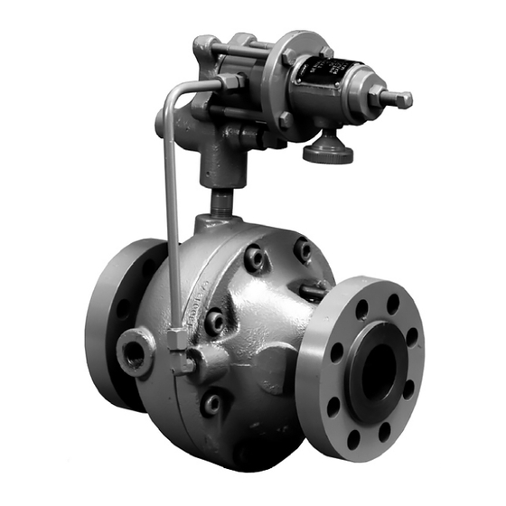
The Type 310A-32A pilot-operated, pressure reducing
regulator includes a single Type 32A pilot mounted
on the Type 310A main valve for pressure reducing or
wide-open monitoring applications.
W6278
Figure 1. Type 310A Regulator with Type 32A Pilot
The Type 310A-32A-32A working monitor regulator
includes Type 310A regulator which functions as the
first-stage regulator in the working monitor situations
by taking the initial pressure reduction and two
Type 32A pilots which serve as the monitoring and
working pilots.
Specifications
Ratings and specifications for the Type 310A
configurations are listed in the Specifications section
on page 2. Some specifications for a specific regulator
are stamped on a nameplate attached to the pilot
spring case (key 1, Figure 9).
www.fisherregulators.com
Type 310A
Advertisement
Table of Contents

Subscribe to Our Youtube Channel
Related Manuals for Emerson Fisher 310A-32A-32A


Summary of Contents for Emerson Fisher 310A-32A-32A
- Page 1 ® operated, and maintained in accordance with federal, state, and local codes, rules and regulations, and Emerson Process Management Regulator Technologies, Inc. instructions. If the regulator vents gas or a leak develops in the system, service to the unit may be required.
-
Page 2: Specifications
Type 310A Specifications Available Configurations Outlet Pressure Ranges and Proportional Bands See Table 1 Type 310A-32A: Type 310A main valve with one Type 32A pilot for standard pressure reducing and Minimum Differential Pressure wide-open monitoring applications 15 psig (1,0 bar) Type 310A-32A-32A: Type 310A main valve with Maximum Travel two Type 32A pilots for working monitor applications... -
Page 3: Principle Of Operation
Type 310A PILOT DIAPhRAgM PLATE AnD YOKE ASSEMBLY PILOT COnTROL SPRIng BLEED VALVE FIXED RESTRICTIOn BOTTOM DIAPhRAgM RELAY SEAT TOP DIAPhRAgM MAIn VALVE DIAPhRAgM ThROTTLIng SLEEVE STATIOnARY A6571 MAIn VALVE SPRIng VALVE PLug InLET PRESSuRE OuTLET PRESSuRE ATMOSPhERIC PRESSuRE LOADIng PRESSuRE PILOT SuPPLY PRESSuRE Figure 2. - Page 4 Type 310A WORKIng PILOT PLug RESTRICTIOn SPACER E0385 PLug InLET PRESSuRE MOnITORIng PILOT OuTLET PRESSuRE ATMOSPhERIC PRESSuRE LOADIng PRESSuRE InTERMEDIATE PRESSuRE PILOT SuPPLY PRESSuRE Figure 3. Type 310A-32A-32A Working Monitor Regulator Operational Schematic Working Monitors (Figure 5) Monitor Systems The Type 310A-32A-32A differs from wide-open Wide-Open Monitors (Figure 4) monitors in that it has working monitor capability.
-
Page 5: Installation And Startup
Type 310A E0695 E0694 Figure 4. Wide-Open Monitor System Figure 5. Working Monitor System Table 3. Maximum Travel only a slight increase in distribution pressure, with BODY SIZE, nPS MAXIMuM TRAVEL, InCh (mm) the Type 310A-32A-32A accomplishing the entire 1 (25) (13) pressure reduction function. -
Page 6: Installation
Type 310A LOADIng TuBIng hAnD VALVE A 1/4 nPT PILOT VEnT VALVE C SuPPLY COnnECTIOn LOCATE 6 TO 10 PIPE DIAMETERS FROM VALVE OuTLET BLOCK VALVE VEnT VALVE E hAnD VALVE B ALTERnATE BLOCK VALVE DOWnSTREAM COnTROL LInE TAP 1/2-InCh (13 mm) DOWnSTREAM COnTROL LInE BYPASS VALVE VEnT VALVE D... -
Page 7: Pilot Adjustment
Type 310A 7. Install a hand valve in the control line. equipment, the only adjustment normally necessary on a Type 310A-32A regulator is the pressure setting 8. Install the other end of the downstream control of the pilot control spring. Turning the adjusting line to the 1/2 NPT connection in either side of the screw clockwise into the spring case increases the case body (key 1, Figure 10 or 11). - Page 8 Type 310A 24B4134 B2445_2 FLEXIBLE WIDE-OPEn MOnITOR ARRAngEMEnT ThAT PERMITS MInIMuM PIPIng WIDE-OPEn MOnITOR ARRAngEMEnT ThAT WIDE-OPEn MOnITOR TO BE EIThER uPSTREAM OR REquIRES WIDE-OPEn MOnITOR ALWAYS TO BE DOWnSTREAM OF ThE WORKIng REguLATOR uPSTREAM OF WORKIng REguLATOR Figure 7. Typical Wide-Open Monitor Installation outlet pressure was factory-set at the mid-range of the of the pilot control spring.
- Page 9 Type 310A hAnD VALVE B WORKIng PILOT hAnD VALVE A MOnITORIng PILOT InTERMEDIATE PRESSuRE DISTRIBuTIOn PRESSuRE A0714_2 Figure 8. Typical Working Monitor Installation Install the Type 310A-32A-32A into the pipeline using Startup adequate gaskets for flanged regulator units and good 1.
-
Page 10: Maintenance
Type 310A Pilot Adjustment venting the inlet pressure to prevent damage caused by reverse pressurization of the pilot or main valve. The second-stage working regulator must be set to operate at a lower pressure than the monitoring pilot Single-Pilot Regulators and Wide-Open or the monitoring pilot will try to take control of the Monitor Regulators distribution pressure. - Page 11 Type 310A conditions and on applicable federal, state and local 10. To inspect or replace the control spring (key 37), codes and regulations. unscrew spring case cap (key 2) and remove the control spring and spring seats (key 5). WARnIng 11.
- Page 12 Type 310A 4. On single-pilot regulators and wide-open CAuTIOn monitor regulators, place the spring (key 36) in the piston guide (key 23). Install the piston, To avoid crushing the diaphragm, do not and secure with the retaining ring (key 27). exceed the torque specified in step 16.
- Page 13 Type 310A disk (key 27), and disk holder (key 28) CAuTIOn need to be replaced. 4. Slide the sleeve and diaphragm assembly out of If the diaphragm in the following step the case body (key 1). is installed with the wrong side against the lower diaphragm plate, the beads 5.
-
Page 14: Parts Ordering
Type 310A Description Part number Table 4. Maximum Cap Screw (key 14) Torque Values Diaphragm (2 required) BODY SIZE, MAXIMuM TORquE VALuE, Nitrile (NBR) 1R742806992 nPS (Dn) FOOT-POunDS (n•m) Fluorocarbon (FKM) 1U448302462 1 (25) (75) Cap Nut, Stainless steel 1D651538992 2 (50) (142) Diaphragm Spacer... - Page 15 Type 310A 34B4129-B Figure 9. Type 32A Pilot Assembly Type 310A Main Valve Description Part number Connector, Carbon-plated steel (not shown) 15A6002X462 Description Part number Type Y602-1 Vent Assembly, for pilot mounted on main valve (not required when pressure loaded) 17A6570X012 Repair Kits (Include keys 6, 9, 11, 19, Drive Screw, 18-8 Stainless steel (4 required)
- Page 16 Type 310A 34B4130-A Figure 10. NPS 1 (DN 25) Body Size Type 310A Main Valve Assembly Description Part number Description Part number Repair Kits (Include keys 6, 9, 11, 19, Case Body, WCC steel (continued) With inlet tapping 26, 27, and 29) (continued) CL300 RF With Fluorocarbon (FKM) O-rings NPS 1 (DN 25)
- Page 17 Type 310A 34B4131-A Figure 11. NPS 2, 3, and 4 (DN 50, 80, and 100) Body Size Type 310A Main Valve Assembly Description Part number Description Part number Base Body, WCC steel (continued) Sleeve, 304 Stainless steel Without travel indicator (standard) NPS 1 (DN 25) 10A8220X012 CL600 RF...
- Page 18 Type 310A Description Part number Cap Screw, Stainless steel (continued) NPS 3 (DN 80) 1R740638982 NPS 3 (DN 80) (NACE) 1R7406X0012 NPS 4 and 4 x 6 (DN 100 and 100 x 150) 1R741338982 NPS 4 (DN 100) (NACE) 1R7413X0012 Washer, Plated steel/composition (for NPS 1 (DN 25) body) (not shown) 1U984499012...
-
Page 19: Mounting Parts
Type 310A TYPE 32A PILOT LOADIng TuBIng ChECK VALVE 14B6654 TYPE 310A MAIn VALVE Figure 13. Backpressure Protection System Assembly Description Part number Description Part number Wiper Ring, Nitrile (NBR) 29* Body Gasket, Nitrile (NBR) (Not for use over 200°F (93°C)) NPS 1 (DN 25) 11A6853X012 NPS 1 (DN 25) - Page 20 For further information visit www.fisherregulators.com The Emerson logo is a trademark and service mark of Emerson Electric Co. All other marks are the property of their prospective owners. Fisher is a mark owned by Fisher Controls, Inc., a business of Emerson Process Management.
Need help?
Do you have a question about the Fisher 310A-32A-32A and is the answer not in the manual?
Questions and answers