Table of Contents
Advertisement
Quick Links
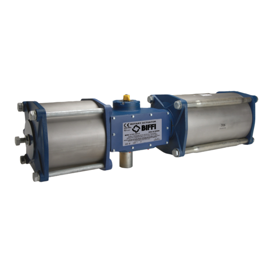
Biffi Morin Series A, B, C, and S
Scotch Yoke Actuators
Copyright © Biffi. The information in this document is subject to change without notice. Updated data sheets can be obtained from our website www.biffi.it or from your nearest Biffi Center:
Biffi Italia s.r.l. - Strada Biffi 165, 29017 Fiorenzuola d'Arda (PC) – Italy PH: +39 0523 944 411 – biffi_italia@biffi.it
Installation, Operation and Maintenance Manual
MAN-03-04-103-0738-EN Rev. 1
May 2020
Advertisement
Table of Contents

Related Manuals for Emerson Biffi Morin Series


Summary of Contents for Emerson Biffi Morin Series
- Page 1 MAN-03-04-103-0738-EN Rev. 1 May 2020 Biffi Morin Series A, B, C, and S Scotch Yoke Actuators Copyright © Biffi. The information in this document is subject to change without notice. Updated data sheets can be obtained from our website www.biffi.it or from your nearest Biffi Center:...
- Page 2 Notes Installation, Operation and Maintenance Manual May 2020 MAN-03-04-103-0738-EN Rev. 1 This page intentionally left blank...
-
Page 3: Table Of Contents
Installation, Operation and Maintenance Manual Table of Contents MAN-03-04-103-0738-EN Rev. 1 May 2020 Table of Contents Section 1: Introduction General Application..................1 Technical Data..................... 1 Installation ....................1 Section 2: Maintenance Maintenance ......................2 Section 3: Jackscrew Override Jackscrew Operating Instructions ..............3 Actuator Stroke Adjustment ................ - Page 4 Table of Contents Installation, Operation and Maintenance Manual May 2020 MAN-03-04-103-0738-EN Rev. 1 Section 9: Removal of Actuator from Valve Removal of Actuator from Valve ................17 Section 10: Disassembly 10.1 Disassembly of Symmetric Yoke Actuators ..........18 10.2 Disassembly of Canted Yoke Actuators ............20 Section 11: Assembly 11.1 Assembly of Symmetric Yoke Actuators ............
-
Page 5: Section 1: Introduction
Installation, Operation and Maintenance Manual Section 1: Introduction MAN-03-04-103-0738-EN Rev. 1 May 2020 Section 1: Introduction General Application Actuators are designed for "ON-OFF" or modulating control of any quarter-turn ball, butterfly, rotary plug or damper style valve application. Technical Data Supply Pressure 40 - 160 psig (2.75 - 11 barg), see product nameplate Supply Medium... -
Page 6: Section 2: Maintenance
Section 2: Maintenance Installation, Operation and Maintenance Manual May 2020 MAN-03-04-103-0738-EN Rev. 1 Section 2: Maintenance Actuators are factory lubricated and in general do not require periodic lubrication or maintenance while in service. Actuators should be visually inspected periodically for corrosion damage and promptly repaired. -
Page 7: Section 3: Jackscrew Override
Installation, Operation and Maintenance Manual Section 3: Jackscrew Override MAN-03-04-103-0738-EN Rev. 1 May 2020 Section 3: Jackscrew Override The jackscrew option is intended for infrequent or emergency on-site operation of the automated valve. Jackscrew Operating Instructions Disengage power supply and vent air from actuator. Operate the handwheel to drive the actuator into the desired position. -
Page 8: Models 370, 575 And 740
Section 3: Jackscrew Override Installation, Operation and Maintenance Manual May 2020 MAN-03-04-103-0738-EN Rev. 1 Models 370, 575 and 740 See Figure 4: Retract the jackscrew override completely by rotating clockwise. Loosen the stroke adjusting screw and lock nut. Using the handwheel, turn the jackscrew to adjust the actuator to the desired position. -
Page 9: Section 4: Actuator Construction
Section 4: Actuator Construction Installation, Operation and Maintenance Manual MAN-03-04-103-0738-EN Rev. 1 May 2020 Section 4: Actuator Construction Single acting Spring-Return Two Pistons Models: 012, 046, 058, 059, 072, 100, 270, 344, 345, 420, 740, 944, 945, 1150, 1480, 1929, 1930, 2380 14 15 17 21 33 34... - Page 10 Section 4: Actuator Construction Installation, Operation and Maintenance Manual May 2020 MAN-03-04-103-0738-EN Rev. 1 Double-Acting Air to Air One Piston Models: 003, 006, 015, 023, 036, 050, 135, 210, 370, 575 YOKE SHOWN AT MID-STROKE, YOKE SHOWN AT MID-STROKE, POINTER OMITTED FOR CLARITY POINTER OMITTED FOR CLARITY SECTION A-A, MODELS 003 - 1150 SECTION A-A, MODELS 003 - 1150...
- Page 11 Section 4: Actuator Construction Installation, Operation and Maintenance Manual MAN-03-04-103-0738-EN Rev. 1 May 2020 Single acting Spring-Return Two Pistons Models: 6044, 7114 Double-Acting Air to Air Two Pistons Models: 1485, 1934, 2385 - 7114 SECTION A-A, MODELS 1480 - 2380 SECTION A-A, MODELS 1485, 1934, 1935, 2385 - 7114 SECTION A-A, MODELS 1480 - 2380 SECTION A-A, MODELS 1485, 1934, 1935, 2385 - 7114...
- Page 12 Section 4: Actuator Construction Installation, Operation and Maintenance Manual May 2020 MAN-03-04-103-0738-EN Rev. 1 Table 1. Materials of Construction S material B material C material A material Item 003-100 135-1150 006-100 135-1150 135-1150 006-100 135-420 Ductile Ductile Housing 316 SS 316 SS Ductile iron Steel...
- Page 13 Section 4: Actuator Construction Installation, Operation and Maintenance Manual MAN-03-04-103-0738-EN Rev. 1 May 2020 S material B material C material A material Item 003-100 135-1150 006-100 135-1150 135-1150 006-100 135-420 Ductile Ductile Ductile End cap 316 SS 316 SS Steel Steel iron iron...
- Page 14 Section 4: Actuator Construction Installation, Operation and Maintenance Manual May 2020 MAN-03-04-103-0738-EN Rev. 1 S Material B material C material Item Item 1480 - 2380 1480 - 2380 1480 - 2380 Housing 316 SS Housing Ductile iron Ductile iron Yoke 17-4 PH Yoke Ductile iron...
- Page 15 Section 4: Actuator Construction Installation, Operation and Maintenance Manual MAN-03-04-103-0738-EN Rev. 1 May 2020 S Material B material C material Item Item 1480 - 2380 1480 - 2380 1480 - 2380 Seal - piston Seal - piston Gasket - housing Fiber Gasket - housing Fiber...
-
Page 16: Section 5: Manual Handpump Hydraulic Override
Section 5: Manual Handpump Hydraulic Override Installation, Operation and Maintenance Manual May 2020 MAN-03-04-103-0738-EN Rev. 1 Section 5: Manual Handpump Hydraulic Override SHUT See Figure 5. Maintain fluid level to fill line using ISO-22 hydraulic fluid. Use Chevron "Hydraulic Oil AW" or equal. The selector control valve is set in center position for remote operation. -
Page 17: Hydraulic Fluid Level
Installation, Operation and Maintenance Manual Section 5: Manual Handpump Hydraulic Override MAN-03-04-103-0738-EN Rev. 1 May 2020 Hydraulic Fluid Level The fluid level in the handpump reservoir changes when the actuator is operated. The fluid level is high when the hydraulic cylinder piston rod is retracted into the hydraulic cylinder. -
Page 18: Section 6: Integral Proximity Switch Mounting
Section 6: Integral Proximity Switch Mounting Installation, Operation and Maintenance Manual May 2020 MAN-03-04-103-0738-EN Rev. 1 Section 6: Integral Proximity Switch Mounting (Only with Prox Prep Factory Ordered Option) Remove plastic plugs from proximity ports located on the back of the actuator housing. -
Page 19: Section 7: Spring Conversion To Change Operating Pressure
Installation, Operation and Maintenance Manual Section 7: Spring Conversion to change Operating Pressure MAN-03-04-103-0738-EN Rev. 1 May 2020 Section 7: Spring Conversion to change Operating Pressure All spring packs except the 40 psi (2.8 bar) consist of an inner and outer spring. The 40 psi (2.8 bar) spring pack uses an outer spring only. -
Page 20: Section 8: Failure Mode Change - Spring-Return
Section 8: Failure Mode Change Installation, Operation and Maintenance Manual May 2020 MAN-03-04-103-0738-EN Rev. 1 Section 8: Failure Mode Change - Spring-Return (Models 003-100) Symmetric Yoke Actuators Only Conversion from "fail close" to "fail open" is accomplished by flipping the actuator over (i.e. -
Page 21: Section 9: Removal Of Actuator From Valve
Installation, Operation and Maintenance Manual Section 9: Removal of Actuator from Valve MAN-03-04-103-0738-EN Rev. 1 May 2020 Section 9: Removal of Actuator from Valve CAUTION Do not attempt to remove mounting bolts between actuator and valve until supply pressure has been disconnected and vented. If spring-return, be sure that valve is completely in failed position. -
Page 22: Section 10: Disassembly
Section 10: Disassembly Installation, Operation and Maintenance Manual May 2020 MAN-03-04-103-0738-EN Rev. 1 Section 10: Disassembly 10.1 Disassembly of Symmetric Yoke Actuators Remove endcap(s) (27); tie rods (41) and cylinder (24). Remove rod cover (28) if applicable. Remove piston bolts (33) and pistons (25) and springs if applicable (55 and 56). Remove adaptor (26) and piston rod seals (29). - Page 23 Installation, Operation and Maintenance Manual Section 10: Disassembly MAN-03-04-103-0738-EN Rev. 1 May 2020 (Models 1480, 1929, 1930, 2380) Remove the pointer (16) and accessory drive (13) from the actuator by removing the screw (14) from inside the yoke (2) bore. Remove all cover bolts (19).
-
Page 24: Disassembly Of Canted Yoke Actuators
Section 10: Disassembly Installation, Operation and Maintenance Manual May 2020 MAN-03-04-103-0738-EN Rev. 1 Figure 7 Figure 8 10.2 Disassembly of Canted Yoke Actuators Canted yoke actuators are disassembled the same way as the symmetric yoke actuators except for the following additional instructions for specific models: (Models 023-100) These actuators are disassembled using the same procedure as the symmetric actuators. -
Page 25: Section 11: Assembly
Installation, Operation and Maintenance Manual Section 11: Assembly MAN-03-04-103-0738-EN Rev. 1 May 2020 Section 11: Assembly 11.1 Assembly of Symmetric Yoke Actuators (Models 003-100) Insert piston rod bushings (7) and output shaft bushings (5) in housing. (On models B-006 through 100 lube output shaft bushings O-rings (48) with "Dow Corning #112"... - Page 26 Section 11: Assembly Installation, Operation and Maintenance Manual May 2020 MAN-03-04-103-0738-EN Rev. 1 Figure 6A Thrust pin access Figure 7A Jack bolts Figure 8A Yoke Slide block and thrust pin Figure 7B Jack bolt Jack bolt Jack bolt Jack bolt Jack bolt Jack bolt Assembly...
- Page 27 Installation, Operation and Maintenance Manual Section 11: Assembly MAN-03-04-103-0738-EN Rev. 1 May 2020 (Models 1480-2380) Install yoke seals (42) using o-ring lube and yoke bearings (5) using WD-40 into the cover (18) and housing (1). Inspect the housing upper and lower vent passages and clear any blockage. Install new vent valves (22).
- Page 28 Section 11: Assembly Installation, Operation and Maintenance Manual May 2020 MAN-03-04-103-0738-EN Rev. 1 (Cylinder and Rod Cover Assembly - All Models) Assemble bolt (33) on end of piston rod before installing rod cover when rod cover is required. Install rod cover (28) if applicable. Actuators utilizing one piston only require a rod cover.
- Page 29 Installation, Operation and Maintenance Manual Section 11: Assembly MAN-03-04-103-0738-EN Rev. 1 May 2020 Table 2. Assembly Torque Requirements (Nm) Model Adaptor Bolt Piston Bolt Tie Rod (41) Tie Rod Bolt Number (44) (33) Spring Side (51) 20.3 13.6 B-006 20.3 20.3 20.3 40.7...
-
Page 30: Spring-Return Only
Section 11: Assembly Installation, Operation and Maintenance Manual May 2020 MAN-03-04-103-0738-EN Rev. 1 11.2 Spring-Return Only (Models S-003 and B-006 only) Place cylinder gasket / O-ring (46) in endcap (54). Place springs in adaptor, being sure to nest in contours. Mount piston (25) over springs and fasten with piston bolt (33) and lock washer (34). -
Page 31: Assembly Of Canted Yoke Actuators
Installation, Operation and Maintenance Manual Section 11: Assembly MAN-03-04-103-0738-EN Rev. 1 May 2020 11.3 Assembly of Canted Yoke Actuators Canted yoke actuators are assembled the same way as the symmetric yoke actuators except for the following additional instructions for specific models. Canted yoke actuators have a non-symmetrical piston rod as well as a non-symmetrical yoke. -
Page 32: Section 12: Operating Instructions
Section 12: Operating Instructions Installation, Operation and Maintenance Manual May 2020 MAN-03-04-103-0738-EN Rev. 1 Section 12: Operating Instructions Operate the actuator in accordance with the pressure and temperature limits specified on the nameplate. See the appropriate Biffi Catalog for technical information. Operating Instructions... -
Page 33: Section 13: Important Safeguards
Installation, Operation and Maintenance Manual Section 13: Important Safeguards MAN-03-04-103-0738-EN Rev. 1 May 2020 Section 13: Important Safeguards CAUTION To reduce the risk of injury: • Read the entire Installation, Operation and Maintenance Manual before installing, operating, or servicing this actuator. •... -
Page 34: Section 14: Additional Safety Instructions For Actuators
Section 14: Additional Safety Instructions Installation, Operation and Maintenance Manual May 2020 MAN-03-04-103-0738-EN Rev. 1 Section 14: Additional Safety Instructions for Actuators used in a Potentially Explosive Atmosphere under ATEX 2014/34/EU 14.1 Marking • ATEX 2014/34/EU, Ex II 2G Ex h IIc T4 Gb 14.2 Selection •... -
Page 35: Or Iec 61508 Safety Integrity Level (Sil)
(proof testing). Any failures effecting functional safety should be reported to the Pelham facility. IEC 61508 (SIL) installations should consult the Emerson factory to obtain the assessment and FMEDA report, which include failure data, PFDAVG, and other associated statistical data to establish or satisfy SIL level or requirements. - Page 36 VCIOM-14630-EN ©2019 Biffi. All rights reserved. Biffi Italia s.r.l. Strada Biffi 165 The contents of this publication are presented for information purposes only, 29017 Fiorenzuola d’Arda (PC) and while every effort has been made to ensure their accuracy, they are not Italy to be construed as warranties or guarantees, express or implied, regarding T +39 0523 944 411...
Need help?
Do you have a question about the Biffi Morin Series and is the answer not in the manual?
Questions and answers