Table of Contents
Advertisement
Instruction Manual
D251402X012
Fisherr 3025 Sizes P460, P462, P460-200, and
P900 Diaphragm Actuator
Contents
. . . . . . . . . . . . . . . . . . . . . . . . . . . . . . . . .
. . . . . . . . . . . . . . . . . . . . . . . . . . . . .
. . . . . . . . . . . . . . . . . . . . . . . . . . . . . . . . .
. . . . . . . . . . . . . . . . . . . . . . . . . . . . . . .
. . . . . . . . . . . . . . . . . . . . . . . . . . . . . . . . . . .
. . . . . . . . . . . . . . . . . . . . . . . . . .
. . . . . . . . . . . . . . . . . . . . . . . . . . . . . . . . .
. . . . . . . . . . . . . . . . . . . . . . . . . . . . . . .
. . . . . . . . . . . . . . . . . . . . . . . . . . . . . . . . . . .
. . . . . . . . . . . . . . . . . . . . . . . . . .
Introduction
Scope of Manual
This instruction manual includes installation, maintenance, and parts information for Fisher 3025 actuators in sizes
P460, P462, P460-200, and P900. Refer to separate manuals for instructions covering the positioner and other
accessories used with these actuators.
Do not install, operate, or maintain 3025 actuators without being fully trained and qualified in valve, actuator, and
accessory installation, operation, and maintenance. To avoid personal injury or property damage, it is important to
carefully read, understand, and follow all the contents of this manual, including all safety cautions and warnings. If you
have any questions about these instructions, contact your Emerson Process Management sales office before
proceeding.
www.Fisher.com
. . . . . . . . . . . .
. . . . . . . . . . . . . . . . . . . . . . .
. . . . . . . . .
. . . . . . . . . . . . . . . . . . . . . . . .
. . . . . . . . . . . . . . . . . . . . . . .
. . . . . . . . . . . . . . . . . . . . . . .
. . . . . . . . . . . . . . . . . .
. . . . . . . . . . . . . . . . . . . . . .
. . . . . . . . .
. . . . . . . . . . . . . . . . . . . .
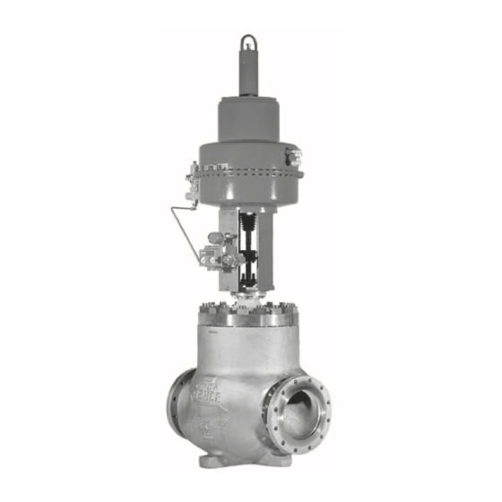
Figure 1. Fisher 3025 Size P460-200 Actuator
1
1
2
2
2
3
4
5
6
6
6
7
9
12
14
18
21
22
22
23
W9088
3025 Actuator
May 2011
Advertisement
Table of Contents

Subscribe to Our Youtube Channel
Related Manuals for Emerson Fisher 3025


Summary of Contents for Emerson Fisher 3025
-
Page 1: Table Of Contents
Introduction Scope of Manual This instruction manual includes installation, maintenance, and parts information for Fisher 3025 actuators in sizes P460, P462, P460-200, and P900. Refer to separate manuals for instructions covering the positioner and other accessories used with these actuators. -
Page 2: Description
D251402X012 Description The Fisher 3025 size P460, P462, P460-200 and P900 spring-opposed diaphragm actuators position the valve plug in the valve body in response to varying controller or valve positioner pneumatic output signals applied to the actuator diaphragm. They can be specified either direct (air-to-close) or reverse acting (air-to-open). The size P460 offers 65 mm maximum actuator travel. -
Page 3: Mounting The Actuator On The Valve
CAUTION The 3025 diaphragm actuators are designed to mount on push-down-to close valves. Do not mount these actuators on any other type of valve without first contacting your Emerson Process Management sales office. Mounting the Actuator on the Valve CAUTION If the valve stem is allowed to remain in the up position (towards the actuator) during mounting, it can interfere with the actuator mounting, possibly damage valve stem threads or bend the valve stem. -
Page 4: Travel Stop Adjustment
Instruction Manual 3025 Actuator May 2011 D251402X012 2. Lift or hoist the actuator onto the valve bonnet: a. For the 3-9/16 yoke boss: Slowly lower the actuator down onto the valve. As the yoke passes over the end of the valve stem, place the yoke locknut over the valve stem. -
Page 5: Installing The Stem Connector Assembly
Fisher Catalog 14, Actuator Sizing and Sample Calculations to determine the correct spring selection for your application. Or contact your Emerson Process Management sales office for assistance. After replacing the spring, repeat the steps above. -
Page 6: Loading Connection
Instruction Manual 3025 Actuator May 2011 D251402X012 11. If the actuator is equipped with a side-mounted handwheel, insert the screw (key 139) and the nut (key 140) into the stem connector half (key 78). Then screw the nut against the stem connector half. Adjust the handwheel travel indicator (key 113) to correspond with the screw (key 139) used as neutral position indicator. -
Page 7: Size P460 Actuator
Instruction Manual 3025 Actuator D251402X012 May 2011 Key numbers refer to figures 3 through 12 unless otherwise indicated. Figure 3 and 4 show the size P460, figure 5 and 6 the size P462, figure 7 and 8 the size P460-200 and figures 9 through 12 illustrate the size P900. It may be necessary to apply a temporary loading pressure to the actuator during the disassembly. - Page 8 Instruction Manual 3025 Actuator May 2011 D251402X012 16. From the diaphragm casing (key 1) remove the retaining ring (key 8), the wiper ring and the seal retainer (keys 4 and 5) and the O-ring (key 6). 17. If required remove the casing bushings (keys 7 and 33), the pins (key 28) from the diaphragm casing and diaphragm plate, the hellicoils (key 58), the travel scale, screw and nuts (keys 74, 75 and 76).
-
Page 9: Size P462 Actuator
Instruction Manual 3025 Actuator D251402X012 May 2011 13. The first four bolts tightened should be diametrically opposed and 90 degrees apart. Tighten these four bolts to 8 NSm (6 lbfSft). 14. Tighten the remaining bolts in a clockwise, crisscross pattern to 8 NSm (6 lbfSft). 15. - Page 10 Instruction Manual 3025 Actuator May 2011 D251402X012 7. Remove the yoke cap screws (key 77), then lift the actuator off the yoke. 8. Remove the lifting lug cap screws (key 44), the lifting lug (key 40), the gasket (key 71) and the spacer if used (key 67).
- Page 11 Instruction Manual 3025 Actuator D251402X012 May 2011 10. Install the diaphragm casing (key 3) so that the vent and air connection are diametrically opposed. Take care when lowering the casing around the stem so that the threads do not damage the bushing. Note When you replace actuator diaphragms in the field, take care to ensure the diaphragm casing bolts are tightened to the proper load to prevent leakage, but not crush the material.
-
Page 12: Size P460-200 Actuator
Instruction Manual 3025 Actuator May 2011 D251402X012 procedures in the Side- Mounted Handwheel Maintenance section to complete the actuator assembly (from step 25. Lift the actuator and place it onto the yoke. Insert the cap screws (key 77) and tighten them. 26. - Page 13 Instruction Manual 3025 Actuator D251402X012 May 2011 16. Unscrew the cap screws (key 25), disassemble the ring (key 24), the diaphragm (key 47) and the diaphragm plate (key 26). 17. Unscrew the cap screws (key 70), remove the wiper ring and the seal retainer (key 4 and 5) and the O-ring (key 6). 18.
-
Page 14: Size P900 Actuator
Instruction Manual 3025 Actuator May 2011 D251402X012 12. Align the diaphragm casings and diaphragm holes. Be sure the vent and air connection on the diaphragm casings are still diametrically opposed. Install the cap screws and nuts (keys 45 and 46). Tighten the diaphragm cap screws and nuts in the following manner. - Page 15 Instruction Manual 3025 Actuator D251402X012 May 2011 6. To separate the actuator from the valve body, remove the yoke locknut or the bolts and then lift off the actuator. 7. Remove the yoke-to-actuator cap screws (key 77), then lift the actuator off the yoke. 8.
- Page 16 Instruction Manual 3025 Actuator May 2011 D251402X012 2. Place the wiper rings (key 4) into the seal retainers (key 5). Apply lithium grease (key 201) to the O-rings (key 6), the wiper ring and seal retainer assemblies and install them into the diaphragm casings (key 1). Then insert the cap screws (key 21) and tighten them.
- Page 17 Instruction Manual 3025 Actuator D251402X012 May 2011 13. Align the diaphragm casings and diaphragm holes. Be sure the vent and air connection on the diaphragm casings are still diametrically opposed. Install the cap screws and nuts (keys 45 and 46). Tighten the diaphragm cap screws and nuts in the following manner.
-
Page 18: Side Mounted Handwheel Maintenance
Instruction Manual 3025 Actuator May 2011 D251402X012 27. Align the diaphragm casings and diaphragm holes. Be sure the vent and air connection on the diaphragm casings are still diametrically opposed. Install the cap screws and nuts (keys 45 and 46). Tighten the diaphragm cap screws and nuts in the following manner. - Page 19 Instruction Manual 3025 Actuator D251402X012 May 2011 Figure 2. Side Mounted Handwheel 3. Remove the stem connector cap screws (key 87), the anti-rotator (key 78), the spacer if used (key 86) and the travel scale indicator (key 85). For the sizes P460, P462 and P460-200, loosen stem connector halves cap screws and nuts (keys 80 and 81) and unscrew the connector halves.
- Page 20 Instruction Manual 3025 Actuator May 2011 D251402X012 14. If required, the driving shaft assembly can be broken down by removing the nut (key 118), the washer (key 117), the rotation indicator (key 114.5), the handwheel (key 116), and then the driving shaft (key 114.4) and the bearing (key 114.3).
-
Page 21: Parts Ordering
Note Neither Emerson, Emerson Process Management, nor any of their affiliated entities assumes responsibility for the selection, use, or maintenance of any product. Responsibility for the selection, use, and maintenance of any product remains with the purchaser and... -
Page 22: Parts List
Jam Hex Nut Note Size P460 and P462 0296759 Part numbers are shown for recommended spares only. For part Hex Head Cap Screw numbers not shown, contact your Emerson Process Management sales Hex Head Cap Screw office. Hex Nut Diaphragm Size P460 0161420 Size P462... -
Page 23: Side-Mounted Handwheel
Instruction Manual 3025 Actuator D251402X012 May 2011 Description Part Number Description Part Number 114.9 Hex Head Cap Screw Lithium Grease 114.10 Hex Nut Anti-Seize Lubricant Hex Head Cap Screw Handwheel Plain Washer Hex Nut Side-Mounted Handwheel Protective Cover Hex Head Cap Screw (figures 13 through 16) Stoppage Part Yoke... - Page 24 Instruction Manual 3025 Actuator May 2011 D251402X012 Key 30 Size P462 Actuator Spring TRAVEL DIAPHRAGM PRESSURE RANGE mm (Inches) 29 (1-1/8) 1.7-2.2 1.7-2.3 38 (1-1/2) 1.7-2.4 1.7-2.5 51 (2) 1.1-1.8 1.6-2.5 1.1-1.9 1.6-2.5 1.1-2.0 1.4-2.5 76 (3) 0.5-0.9 1.1-2.2 1.5-2.4 0.5-0.9 1.1-2.3 1.5-2.4...
-
Page 25: D251402X012 May
Instruction Manual 3025 Actuator D251402X012 May 2011 Figure 3. Fisher 3025 Size P460 Air-to-Open Actuator APPLY LUBRICANT... - Page 26 Instruction Manual 3025 Actuator May 2011 D251402X012 Figure 4. Fisher 3025 Size P460 Air-to-Close Actuator APPLY LUBRICANT...
- Page 27 Instruction Manual 3025 Actuator D251402X012 May 2011 Figure 5. Fisher 3025 Size P462 Air-to-Open Actuator APPLY LUBRICANT...
- Page 28 Instruction Manual 3025 Actuator May 2011 D251402X012 Figure 6. Fisher 3025 Size P462 Air-to-Close Actuator APPLY LUBRICANT...
- Page 29 Instruction Manual 3025 Actuator D251402X012 May 2011 Figure 7. Fisher 3025 Size P460-200 Air-to-Open Actuator APPLY LUBRICANT...
- Page 30 Instruction Manual 3025 Actuator May 2011 D251402X012 Figure 8. Fisher 3025 Size P460-200 Air-to-Close Actuator APPLY LUBRICANT...
- Page 31 Instruction Manual 3025 Actuator D251402X012 May 2011 Figure 9. Fisher 3025 Size P900 Air-to-Open Actuator APPLY LUBRICANT...
- Page 32 Instruction Manual 3025 Actuator May 2011 D251402X012 Figure 10. Fisher 3025 Size P900 Air-to-Close Actuator APPLY LUBRICANT...
- Page 33 Instruction Manual 3025 Actuator D251402X012 May 2011 Figure 11. Fisher 3025 Size P900 Air-to-Open Actuator (long stroke high bench set) APPLY LUBRICANT...
- Page 34 Instruction Manual 3025 Actuator May 2011 D251402X012 Figure 12. Fisher 3025 Size P900 Air-to-Close Actuator (long stroke high bench set) APPLY LUBRICANT...
- Page 35 Instruction Manual 3025 Actuator D251402X012 May 2011 Figure 13. Fisher 3025 Size P460 and P462 Side Mounted Handwheel APPLY LUBRICANT...
- Page 36 Instruction Manual 3025 Actuator May 2011 D251402X012 Figure 14. Fisher 3025 Size P900 Side Mounted Handwheel APPLY LUBRICANT...
- Page 37 Instruction Manual 3025 Actuator D251402X012 May 2011 Figure 15. Fisher 3025 Size P460-200 Side Mounted Handwheel APPLY LUBRICANT...
- Page 38 Instruction Manual 3025 Actuator May 2011 D251402X012 Figure 16. Fisher Driving Shaft Assembly for all Side Mounted Handwheel Sizes APPLY LUBRICANT...
- Page 39 Instruction Manual 3025 Actuator D251402X012 May 2011...
- Page 40 Fisher is a mark owned by one of the companies in the Emerson Process Management business division of Emerson Electric Co. Emerson Process Management, Emerson, and the Emerson logo are trademarks and service marks of Emerson Electric Co. All other marks are the property of their respective owners.
Need help?
Do you have a question about the Fisher 3025 and is the answer not in the manual?
Questions and answers