Table of Contents
Advertisement
Quick Links
Advertisement
Table of Contents

Related Manuals for Universal Robots UR10/CB3


Summary of Contents for Universal Robots UR10/CB3
- Page 1 Universal Robots User Manual UR10/CB3 Original instructions (en)
- Page 2 The information contained herein is the property of Universal Robots A/S and shall not be reproduced in whole or in part without prior written approval of Universal Robots A/S. The information herein is subject to change without notice and should not be construed as a commitment by Universal Robots A/S.
-
Page 3: Table Of Contents
Contents 1. Preface 1.1. What Do the Boxes Contain 1.2. Important Safety Notice 1.3. How to Read This Manual 1.4. Where to Find More Information 1.4.1. UR+ Part I Hardware Installation Manual 1.5. Safety 1.5.1. Introduction 1.5.2. Validity and Responsibility 1.5.3. Limitation of Liability 1.5.4. - Page 4 1.9.5. Ethernet 1.9.6. Mains connection 1.9.7. Robot connection 1.10. Maintenance and Repair 1.10.1. Safety Instructions 1.10.2. Cleaning 1.11. Disposal and Environment 1.12. Certifications 1.13. Warranties 1.13.1. Product Warranty 1.13.2. Disclaimer 1.14. Stopping Time and Stopping Distance 1.14.1. Stop Category 0 stopping distances and times 1.15.
- Page 5 Maximum Speed Position Range 1.20.12. Boundaries Name Copy Feature Safety mode Displacement Effect of strict limit planes Effect of Trigger Reduced mode planes Deviation Copy Feature Safety mode Effect 1.20.13. Safety I/O System Emergency Stop Reduced Mode Safeguard Reset Three-Position Enabling Device and Operational Mode System Emergency Stop Robot Moving Robot Not Stopping...
- Page 6 1.23.2. I/O Tab 1.23.3. MODBUS 1.23.4. AutoMove Tab 1.23.5. Installation → Load/Save 1.23.6. Installation → TCP Configuration 1.23.7. Installation → Mounting 1.23.8. Installation → I/O Setup 1.23.9. Installation → Safety 1.23.10. Installation → Variables 1.23.11. Installation → MODBUS client I/O Setup 1.23.12.
- Page 7 1.24.9. Command: Until 1.24.10. Command: Wait 1.24.11. Command: Set 1.24.12. Command: Popup 1.24.13. Command: Halt 1.24.14. Command: Comment 1.24.15. Command: Folder 1.24.16. Command: Loop 1.24.17. Command: If 1.24.18. Command: SubProgram 1.24.19. Command: Assignment 1.24.20. Command: Script 1.24.21. Command: Event 1.24.22. Command: Thread 1.24.23.
- Page 8 1.26.1. EUROMAP 67 standard 1.26.2. Statutory notice 1.27. Robot and IMM integration 1.27.1. Emergency stop and safeguard stop 1.27.2. Connecting a MAF light guard 1.27.3. Mounting the robot and tool 1.27.4. Using the robot without an IMM 1.27.5. EUROMAP 12 to EUROMAP 67 conversion 1.28.
-
Page 9: Preface
1. Preface 1. Preface Congratulations on the purchase of your new Universal Robots robot. The robot can be programmed to move a tool, and communicate with other machines using electrical signals. It is an arm composed of extruded aluminium tubes and joints. -
Page 10: How To Read This Manual
1. Preface 1.3. How to Read This Manual This manual contains instructions for installing and programming the robot. The manual is separated into two parts: Hardware Installation Manual The mechanical and electrical installation of the robot. PolyScope Manual Programming of the robot. EUROMAP 67 Interface Using the EUROMAP 67 interface. -
Page 11: Part I Hardware Installation Manual
Part I Hardware Installation Manual Part I Hardware Installation Manual User Manual UR10... - Page 12 Part I Hardware Installation Manual UR10 User Manual...
-
Page 13: Safety
Special attention shall be paid to text associated with warning symbols. NOTE Universal Robots disclaims any and all liability if the robot (arm control box and/or teach pendant) is damaged, changed or modified in any way. Universal Robots cannot be held responsible for any damages caused to the robot or any other equipment due to programming errors or malfunctioning of the robot. -
Page 14: Limitation Of Liability
• Marking the robot installation with relevant signs and contact information of the integrator • Collecting all documentation in a technical file; including the risk assessment and this manual 1.5.3. Limitation of Liability Any safety information provided in this manual must not be construed as a warranty, by UR, that the industrial manipulator will not cause injury or damage, even if industrial manipulator complies with all safety instructions. -
Page 15: General Warnings And Cautions
1.5.5. General Warnings and Cautions This section contains some general warnings and cautions that can be repeated or explained in different parts of this manual. Other warnings and cautions are present throughout this manual. WARNING You must install the robot and all electrical equipment according to the specifications and warnings found in chapters 1.8. - Page 16 WARNING 1. Make sure the robot arm and tool/end effector are properly and securely bolted in place. 2. Make sure the robot arm has ample space to operate freely. 3. Make sure that safety measures and/or robot safety configuration parameters have been set up to protect both programmers, operators and bystanders, as defined in the risk assessment.
-
Page 17: Intended Use
according to the newest version of all relevant service manuals. 16. If the robot is purchased with an extra module (e.g. euromap67 interface) then look up that module in the respective manual. WARNING 1. The robot and its controller box generate heat during operation. Do not handle or touch the robot while in operation or immediately after operation as prolonged contact can cause discomfort. -
Page 18: Risk Assessment
• Use outside of stated specifications • Use as a climbing aid • Operation outside the permissible operating parameters 1.5.7. Risk Assessment One of the most important things that an integrator needs to do is to perform a risk assessment. In many countries this is required by law. -
Page 19: Emergency Stop
(e.g. an enabling device to protect the operator during set-up and programming). Universal Robots identifies the potential significant hazards listed below as hazards that must be considered by the integrator. -
Page 20: Movement With And Without Drive Power
1.5.9. Movement With and Without Drive Power In the unlikely event of an emergency situation, where one or more robot joints need to be moved and robot power is either not possible or not wanted, there are two different ways to force movements of the robot joints: Note: In a service situation, the brake on the joints can be released without connected power. -
Page 21: Safety-Related Functions And Interfaces
1.6. Safety-related Functions and Interfaces 1.6.1. Introduction UR robots are equipped with a range of built-in safety-related functions as well as safety-related electrical interfaces to connect to other machines and additional protective devices. Each safety function and interface is monitored according to EN ISO13849-1:2008 (see Chapter for certifications) with Performance Level d (PLd). -
Page 22: Stopping Times Of The Safety System
Limiting Safety Function Description TCP force Max. pushing force of the robot TCP Momentum Max. momentum of the robot arm Power Max. applied robot arm power 1.6.2. Stopping times of the Safety System The stopping time of the safety system is the time from a fault or violation of a safety-related function occurs to the robot is brought to a complete stop and the mechanical brakes are engaged. - Page 23 WARNING There are two exceptions to the force limiting function that are important to notice when designing the work cell for the robot. These are illustrated in Figure 4.1. As the robot stretches out, the knee-joint effect can give high forces in the radial direction (away from the base), but at the same time, low speeds.
-
Page 24: Safety Modes
1.6.4. Safety Modes Normal and Reduced mode The safety system has two configurable safety modes: Normal and Reduced. Safety limits can be configured for each of these two modes. Reduced mode is active when the robot TCP is positioned beyond a Trigger Reduced mode plane or when triggered by a safety input. Reduced mode can be triggered either by using a plane or by using an input. -
Page 25: Safety-Related Electrical Interfaces
1.6.5. Safety-related Electrical Interfaces The robot is equipped with several safety-related electrical inputs and outputs. All safety-related electrical inputs and outputs are dual channel. They are safe when low, e.g. the emergency stop is not active when the signals are high (+24V). Safety-related Electrical Inputs The table below gives an overview of the safety-related electrical inputs. - Page 26 Monitoring of safety inputs [rad/s] Max joint speed in normal mode time 0.024 0.524 4.2: The green area below the ramp is the allowed speeds for a joint during braking. At time 0 an event (emergency stop or safeguard stop) is detected at the safety processor. Deceleration begins after 24 ms.
- Page 27 Emergency Stop Button 250 ms 1000 ms 1250 ms System Emergency Stop 250 ms 1000 ms 1250 ms Safeguard Stop 250 ms 1000 ms 1250 ms Safety-related Electrical Outputs The table below gives an overview of the safety-related electrical outputs: Safety Description Output System Logic low when the Robot emergency stop input is logic low or the Emergency Emergency stop button is pressed.
- Page 28 UR10 User Manual...
-
Page 29: Transportation
1. Make sure not to overload your back or other bodyparts when the equipment is lifted. Use proper lifting equipment. All regional and national guidelines for lifting shall be followed. Universal Robots cannot be held responsible for any damage caused by transportation of the equipment. - Page 30 UR10 User Manual...
-
Page 31: Mechanical Interface
1.8. Mechanical Interface 1.8.1. Introduction This chapter describes the basics of mounting the various parts of the robot system. Electrical installation instructions in chapter 1.9. Electrical Interface on page 29 must be observed. 1.8.2. Workspace of the Robot The workspace of the robot extends 1300 mm from the base joint. It is important to consider the cylindrical volume directly above and directly below the robot base when a mounting place for the robot is chosen. - Page 32 The robot arm is mounted using four M8 bolts, using the four 8.5 mm holes on the base. It is recommended to tighten these bolts with 20 N m torque. If very accurate repositioning of the robot arm is desired, two Ø8 holes are provided for use with a pin. Also, an accurate base counterpart can be purchased as an accessory.
- Page 33 6.1: Holes for mounting the robot. Use four M8 bolts. All measurements are in mm . Tool The robot tool flange has four M6 thread holes for attaching a tool to the robot. The M6 bolts need to be tightened with 9 N m. If very accurate repositioning of the tool is desired, the Ø6 hole is provided for use with a pin.
-
Page 34: Maximum Payload
6.2: The tool output flange, ISO 9409-1-50-4-M6. This is where the tool is mounted at the tip of the robot. All measures are in mm . Control Box The control box can be hung on a wall, or it can be placed on the ground. A clearance of 50 mm on each side is needed for sufficient airflow. - Page 35 Payload [kg] Center of gravity offset [mm] 6.3: Relationship between the maximum allowed payload and the center of gravity offset. User Manual UR10...
- Page 36 UR10 User Manual...
-
Page 37: Electrical Interface
1.9. Electrical Interface 1.9.1. Introduction This chapter describes all the electrical interfaces of the robot arm and control box. The different interfaces are divided into five groups with different purposes and properties: • Controller I/O • Tool I/O • Ethernet •... -
Page 38: Controller I/O
EMC problems are found to happen usually in welding processes and are normally prompted by error messages in the log. Universal Robots cannot be held responsible for any damages caused by EMC problems. 2. I/O cables going from the control box to other machinery and factory equipment may not be longer than 30m, unless extended tests are performed. - Page 39 The illustration below shows the layout of electrical interface inside the control box. Safety Remote Power ConfigurablebInputs ConfigurablebOutputs DigitalbInputs DigitalbOutputs Analog The meaning of the different colors must be observed, see below. Yellow with red text Dedicated safety signals Yellow with black text Configurable for safety Gray with black text General purpose digital I/O...
- Page 40 Power The electrical specifications for both the internal and an external power supply are shown below. Terminals Parameter Unit Internal 24V power supply Voltage [PWR - GND] Current [PWR - GND] External 24V input requirements Voltage [24V - 0V] Current [24V - 0V] The digital I/O are constructed in compliance with IEC 61131-2.
- Page 41 Safety I/O This section describes the dedicated safety inputs (Yellow terminal with red text) and the configurable I/O (Yellow terminals with black text) when configured as safety I/O. The common specifications in section Common specifications for all digital I/O on page 31 must be observed. Safety devices and equipment must be installed according to the safety instructions and the risk assessment (see chapter 1.5.
- Page 42 WARNING 1. Never connect safety signals to a PLC which is not a safety PLC with the correct safety level. Failure to follow this warning could result in serious injury or death as the safety functions could be overridden. It is important to keep safety interface signals separated from the normal I/O interface signals.
- Page 43 The Robot Emergency Stop input cannot be used for sharing purposes, since both machines will wait for the each other to go out of the emergency stopped condition. In order to share the emergency stop function with other machinery, the following configurable I/O functions must be configured through the GUI.
- Page 44 Safety WARNING 1. The robot resumes movement automatically when the safeguard signal is re-established. Do not use this configuration if signal can be re-established from the inside of the safety perimeter. Safeguard stop with reset button If the safeguard interface is used to interface a light curtain, a reset outside the safety perimeter is required.
- Page 45 NOTE The Universal Robots safety system does not support multiple Three-Position Enabling Devices. Configurable Inputs 3-Position Switch NOTE The two input channels for the Three-Position Enabling Device input have a disagreement tolerance of 1 second. General purpose digital I/O This section describes the general purpose 24V I/O (Gray terminals) and the configurable I/O (Yellow terminals with black text) when not configured as safety I/O.
- Page 46 Digital input from a button The example below shows how to connect a simple button to a digital input. Digital Inputs Communication with other machines or PLCs The digital I/O can be used to communicate with other equipment if a common GND (0V) is established and if the machine uses PNP technology, see below.
- Page 47 Terminals Parameter Unit Resolution [AIx - AG] Analog input in voltage mode Voltage [AIx - AG] Resistance Kohm [AIx - AG] Resolution [AIx - AG] Analog output in current mode Current [AOx - AG] Voltage [AOx - AG] Resolution [AOx - AG] Analog output in voltage mode Voltage [AOx - AG]...
- Page 48 Analog Power Remote ON/OFF control Remote ON/OFF control can be used to turn the control box on and off without using the teach pendant. It is typically used in the following applications: • When the teach pendant is inaccessible. • When a PLC system must have full control. •...
-
Page 49: Tool I/O
CAUTION 1. Never use the “on” input or the power button to turn off the control box. Remote ON button The illustration below shows how to connect a remote on button. Remote Remote OFF button The illustration below shows how to connect a remote off button. Remote 1.9.4. - Page 50 Color Signal 0V (GND) Gray 0V/+12V/+24V (POWER) Blue Tool output 0 (TO0) Pink Tool output 1 (TO1) Yellow Tool input 0 (TI0) Green Tool input 1 (TI1) White Analog input 2 (AI2) Brown Analog input 3 (AI3) The internal power supply can be set to either 0V, 12V or 24V at the I/O tab the GUI, see part Part II PolyScope Manual on page 85.
- Page 51 Parameter Unit Current when sinking Current through GND An example of how to use a digital output is shown in the following subsection. CAUTION 1. The digital outputs in the tool are not current limited and overriding the specified data can cause permanent damage. Using the Tool Digital Outputs The example below illustrates how to turn on a load, when using the internal 12V or 24V power supply.
- Page 52 Using the Tool Digital Inputs The example below shows how to connect a simple button. POWER Tool Analog Inputs The tool analog inputs are non-differential and can be set to either voltage and current on the I/O tab, see part Part II PolyScope Manual on page 85.
-
Page 53: Ethernet
POWER Using the Tool Analog Inputs, Differential The example below shows how to connect an analog sensor with a differential output. Connect the negative output part to GND (0V) and it works in the same way as a non-differential sensor. POWER 1.9.5. - Page 54 The mains supply shall be equipped with the following as a minimum: • Connection to earth. • Main fuse. • Residual current device. It is recommended to install a main switch to power off all equipment in the robot application as an easy means for lockout and tagout under service.
-
Page 55: Robot Connection
1.9.7. Robot connection The cable from the robot must be plugged into the connector at the bottom of the control box, see illustration below. Ensure that the connector is properly locked before turning on the robot arm. Disconnecting the robot cable may only be done when the robot power is turned off. CAUTION 1. - Page 56 UR10 User Manual...
-
Page 57: Maintenance And Repair
Service Manual. See the Service Manual: Chapter 5 for full inspection plan for trained individuals All parts returned to Universal Robots shall be returned according to terms in the Service Manual. 1.10.1. Safety Instructions After maintenance and repair work, checks must be done to ensure the required safety level. -
Page 58: Cleaning
WARNING 1. Remove the mains input cable from the bottom of the control box to ensure that it is completely unpowered. Deenergize any other source of energy connected to the robot arm or control box. Take necessary precautions to prevent other persons from energizing the system during the repair period. 2. -
Page 59: Disposal And Environment
Fee for disposal and handling of electronic waste of UR robots sold on the Danish market is prepaid to DPA-system by Universal Robots A/S. Importers in countries covered by the European WEEE Directive 2012/19/EU must make their own registration to the national WEEE register of their country. - Page 60 Although they are primarily relevant for Europe, some countries outside Europe recognize and/or require EU declarations. European directives are available on the official homepage: http://eur-lex.europa.eu. Universal Robots robots are certified according to the directives listed below. 2006/42/EC Machine Directive According to the Machinery Directive...
- Page 61 Declarations According to EU directives 2006/95/EC Low Voltage Directive In the Declaration of Incorporation in appendix (LVD) B, declarations of conformity with the above directives are listed. 2004/108/EC Electromagnetic A CE mark is affixed according to the CE Compatibility (EMC) marking directives above.
- Page 62 UR10 User Manual...
-
Page 63: Warranties
Warranty default becoming evident. Ownership of devices or components replaced by and returned to Universal Robots shall vest in Universal Robots. Any other claims resulting out of or in connection with the device shall be excluded from this Warranty. Nothing in this Warranty shall attempt to limit or exclude a Customer’s Statutory Rights nor the manufacturer’s liability for... - Page 64 UR10 User Manual...
-
Page 65: Stopping Time And Stopping Distance
1. According to IEC 60204-1, see Glossary for more details.↩ 1.15. Declarations and Certificates EU Declaration of Incoporation in accordance with ISO/IEC 17050-1:2010 Manufacturer Universal Robots A/S Energivej 25 DK-5260 Odense S Denmark Person in the Community David Brandt Technology Officer, Research and Development... - Page 66 Serial Number Starting 20183000000 and higher --- Effective 1 January 2018 Incorporation: Universal Robots (UR3, UR5, and UR10) shall only be put into service upon being integrated into a final complete machine (robot system, cell or application), which conforms with the provisions of the Machinery Directive and other applicable Directives.
- Page 67 Reference to Other Technical (I) ISO/TS 15066 as applicable Standards and Specifications (II) IEC 61784-3:2010 [SIL2] Used: ISO 14664-1:2015 Class 5 for control assembly with enclosure and Class 5 for UR3, UR5 and UR10 manipulators (II) IEC 60664-5:2007 (III) IEC 60068-2-27:2008, (III) IEC 60068-2-1:2007 (III) IEC 60068-2-2:2007, (III) IEC 61326-3-1:2008 The manufacturer, or his authorized representative, shall transmit relevant information about the partly completed machinery in response to a reasoned request by the national authorities.
- Page 68 Safety System Certificate UR10 User Manual...
- Page 69 TUV Rheinland User Manual UR10...
- Page 70 Industrie Service GmbH hereby confirms UNIVERSAL ROBOTS A/S situated at Energivej 25, 5260 Odense S; Dänemark, that the product ROBOTER, MODEL: UR10 / TYP INDUSTRIAL the cleanroom compatibility of the equipment for the ISO Class 5 according ISO 14644-1. The certificate is limited to the particulate cleanliness. The product was tested according to VDI 2083 Part 9.1 in August...
- Page 71 Service GmbH hereby confirms UNIVERSAL ROBOTS A/S situated at Energivej 25, 5260 Odense S; Dänemark, that the product CONTROLLER for UR 3 / UR 5 / UR 10 the cleanroom compatibility of the equipment for the ISO Class 6 according ISO 14644-1.
- Page 72 China RoHS UR10 User Manual...
- Page 73 KCC Safety User Manual UR10...
- Page 74 KC Registration UR10 User Manual...
- Page 75 Environmental Test Certificate Climatic and mechanical assessment Client Force Technology project no. Universal Robots A/S 117-32120 Energivej 25 5260 Odense S Denmark Product identification UR 3 robot arms UR 3 control boxes with attached Teach Pendants. UR 5 robot arms UR5 control boxes with attached Teach Pendants.
- Page 76 Energy Agency in Denmark to carry out tasks referred to in Annex III of the European Council EMC Directive. The attestation of conformity is in accordance with the essential requirements set out in Annex I. DELTA client Universal Robots A/S Energivej 25 5260 Odense S Denmark Product identification (type(s), serial no(s).)
-
Page 77: Applied Standards
1.16. Applied Standards This section describes relevant standards applied under the development of the robot arm and control box. A European Directive number appearing in brackets indicates the standard is harmonized according to that Directive. A standard is not a law, but a document developed by stakeholders within a given industry. Standards define the normal safety and performance requirements for a product or product group. - Page 78 ISO 12100:2010 EN ISO 12100:2010 (E) [2006/42/EC] Safety of machinery – General principles for design – Risk assessment and risk reduction UR robots are evaluated according to the principles of this standard. ISO 10218-1:2011 EN ISO 10218-1:2011(E) [2006/42/EC] Robots and robotic devices – Safety requirements for industrial robots Part 1: Robots This standard is intended for the robot manufacturer, not the integrator.
- Page 79 The language is changed from British English to American English, but the content is the same. Part two (ISO 10218-2) of this standard is intended for the integrator of the robot system, and not Universal Robots. CAN/CSA-Z434-14 Industrial Robots and Robot Systems – General Safety Requirements...
- Page 80 CSA added additional requirements for the user of the robot system. Some of these requirements might need to be addressed by the robot integrator. Part two (ISO 10218-2) of this standard is intended for the integrator of the robot system, and not Universal Robots. IEC 61000-6-2:2005 IEC 61000-6-4/A1:2010...
- Page 81 These two standards are very similar. They define safety principles for avoiding unexpected start-up, both as a result of unintended repowering during maintenance or repair, and as a result of unintended start-up commands from a control perspective. IEC 60947-5-5/A1:2005 EN 60947-5-5/A11:2013 [2006/42/EC] Low-voltage switchgear and controlgear Part 5-5: Control circuit devices and switching elements - Electrical emergency stop device with mechanical latching function...
- Page 82 ISO 13732-1:2006 EN ISO 13732-1:2008 [2006/42/EC] Ergonomics of the thermal environment – Methods for the assessment of human responses to contact with surfaces Part 1: Hot surfaces The UR robots are designed so that the surface temperature is kept under the ergonomic limits defined in this standard.
- Page 83 IEC 61784-3:2010 EN 61784-3:2010 [SIL 2] Safety of machinery – Electrical equipment of machines Part 1: General requirements The general principles of this standard are applied. IEC 60664-1:2007 IEC 60664-5:2007 EN 60664-1:2007 [2006/95/EC] EN 60664-5:2007 Insulation coordination for equipment within low-voltage systems Part 1: Principles, requirements and tests Part 5: Comprehensive method for determining clearances and creepage distances equal to or less than 2 mm...
-
Page 84: Technical Specifications
1.17. Technical Specifications Robot type UR10 Weight 28.9 kg / 63.7 lb Maximum payload 10 kg / 22 lb Reach 1300 mm / 51.2 in Joint ranges ± 360 ° for all joints Base and Shoulder joints: Max 120 °/s. All other Speed joints: Max 180 °/s . Tool: Approx. 1 Approx. 39.4 Pose Repeatability ±... -
Page 85: Safety Functions Tables
1.18. Safety Functions Tables 1.18.1. Table 1: Safety Functions (SF) Descriptions NOTE The Safety Functions tables presented in this chapter are simplified. You can find the comprehensive versions of them here: https://www.universal- robots.com/support All safety functions are individual safety functions. Safety What is Description... - Page 86 Safety What is Description Function controlled? This safety function is initiated by an external protective device using safety inputs which will initiate a Cat 2 stop Safeguard per IEC 60204-1. For the functional safety rating of the Logic and stop complete integrated safety function, add the PFHd of the Robot Arm outputs...
- Page 87 Safety What is Description Function controlled? Exceeding the TCP force limit results in a Cat 0 stop5 (IEC Force 60204-1). Limits the external clamping force exerted by the Internal Limit robot. See also Joint Torque Limit (SF5). Exceeding the momentum limit results in a Cat 0 stop5 (IEC Joint 60204-1).
- Page 88 Safety What is Description Function controlled? SF14 Whenever the robot is in reduced mode, the dual digital Internal UR Robot External outputs are LOW. See Robot Reduced Mode below. The as a Reduced connection functional safety rating is for what is within the UR robot. function Mode: to logic...
- Page 89 NORD Safety What is Description Certified Function controlled? When the external Enabling Device connections are Low, a Safeguard Stop (SF2) is initiated. Recommendation: Use with a mode switch as a safety input. If a mode switch is External not used and connected to the safety inputs, then the robot Enabling mode will be determined by the User Interface.
- Page 90 IEC 61800-5-2 Limits or Stop: power to USER final switching NORD Stop Category PFHd UR Safety Function configuration devices Certified per IEC 60204-1 3/5/10 or Factory retained for Setting Category 2 stop Emergency Stop Cat 1 Stop when SS1 when at There are two at SS1 SS1 standstill,...
- Page 91 IEC 61800-5-2 Limits or Stop: power to USER PFHd NORD Stop Category final switching Safety Function configuration Certified per IEC 60204-1 devices or Factory 3/5/10 retained for Setting Category 2 stop UR Robot Not Output & I/O 3.15E- SF13 stopping: Cat 0 Configuration Digital Output...
- Page 92 UR10 User Manual...
-
Page 93: Part Ii Polyscope Manual
Part II PolyScope Manual Part II PolyScope Manual User Manual UR10... - Page 94 Part II PolyScope Manual UR10 User Manual...
-
Page 95: Safety Configuration
1.20. Safety Configuration 1.20.1. Introduction The robot is equipped with an advanced safety system. Depending on the particular characteristics of the robot workspace, the settings for the safety system must be configured to guarantee the safety of all personnel and equipment around the robot. Applying settings defined by the risk assessment is the first thing the integrator must do. - Page 96 The safety settings consist of a number of limit values used to constrain the movements of the robot arm, and of safety function settings for the configurable inputs and outputs. They are defined in the following subtabs of the safety screen: •...
-
Page 97: Changing The Safety Configuration
1.20.2. Changing the Safety Configuration The safety configuration settings shall only be changed in compliance with the risk assessment conducted by the integrator. The recommended procedure for changing the safety configuration is as follows: 1. Make sure that the changes are in compliance with the risk assessment conducted by the integrator. -
Page 98: Tolerances
If no errors exist and attempting to navigate away, a different dialog appears with the following options: 1. Apply changes and restart the system. This will apply the safety configuration modifications to the system and restart. Note: This does not imply that any changes have been saved;... -
Page 99: Safety Modes
1.20.6. Safety Modes Under normal conditions (i.e. when no protective stop is in effect), the safety system operates in one of the following safety modes, each with an associated set of safety limits: Normal mode The safety mode that is active by default; Reduced mode Active when the robot TCP is positioned beyond a Trigger Reduced mode plane (see 1.20.13. -
Page 100: Password Lock
Backdrive In Freedrive mode, the robot joints can be moved with relatively little force because the brakes are released. During initialization of the robot arm, minor vibrations may be observed when the robot brakes are released. In some situations, such as when the robot is close to collision, these tremors are undesirable and the Backdrive feature can be used to forcefully move specific joints to a desired position without releasing all brakes in the robot arm. -
Page 101: General Limits
Furthermore, on confirmation the changes are automatically saved as part of the current robot See 1.23.5. Installation → Load/Save on page 126 installation. for further information on saving the robot installation. 1.20.10. General Limits The general safety limits serve to limit the linear speed of the robot TCP as well as the force it may exert on the environment. -
Page 102: Basic Settings
Defining the general safety limits only defines the limits for the tool, and not the overall limits of the robot arm. This means that although a speed limit is specified, it does not guarantee that other parts of the robot arm will obey this same limitation. When in Freedrive mode (see Freedrive on page 122), and the current speed of the robot TCP is... -
Page 103: Switching To Basic Settings
Here, each of the general limits, described in 1.20.10. General Limits on page 93, can be modified independently of the others. This is done by tapping the corresponding text field and entering the new value. The highest accepted value for each of the limits is listed in the column titled Maximum. -
Page 104: Joint Limits
1.20.11. Joint Limits Joint limits restrict the movement of individual joints in joint space, i.e. they do not refer to Cartesian space but rather to the internal (rotational) position of the joints and their rotational speed. The radio buttons in the upper portion of the subpanel make it possible to independently set up Maximum Speed and Position Range for the joints. -
Page 105: Position Range
The tolerance and unit for each limit are listed at the end of the row that corresponds to it. When a program is running, the speed of the robot arm is automatically adjusted in order to not exceed any of the entered values minus the tolerance (see 1.20.4. - Page 106 NOTE It is highly recommended, that you create all features needed for the configuration of all the desired boundary limits and assign them appropriate names before editing the safety configuration. Note that since the robot arm is powered off once the Safety tab has been unlocked, the Tool feature (containing the current position and orientation of the robot TCP) as well as Freedrive mode (see Freedrive on page 122) will not be available.
-
Page 107: Name
The (active) safety planes are shown in yellow and black with a small arrow representing the plane normal, which indicates the side of the plane on which the robot TCP is allowed to be positioned. Trigger planes are displayed in blue and green. A small arrow illustrates the side of the plane that does not trigger the transition into Reduced mode. -
Page 108: Copy Feature
Copy Feature The position and normal of the safety plane is specified using a feature (see 1.23.12. Installation → Features on page 140) from the current robot installation. Use the drop-down box in the lower left portion of the Safety Plane Properties section to select a feature. Only the point and plane type features are available. -
Page 109: Displacement
Displacement When a feature has been selected in the drop down box in the lower left portion of the Safety Plane Properties panel, the safety plane can be translated by tapping the Displacement text field in the lower right portion of this panel and entering a value. Entering in a positive value increases the allowed workspace of the robot by moving the plane in the opposite direction of the plane normal, while entering a negative value decreases the allowed area by moving the plane in the direction of the plane normal. -
Page 110: Deviation
robot TCP is positioned 20 mm or further from the Trigger Reduced mode plane (on the Normal mode side), the Reduced mode limit set is no longer active and the Normal mode limit set is enforced. If the predicted trajectory takes the robot TCP through a Trigger Reduced mode plane, the robot arm will start decelerating even before passing through the plane if it is about to exceed joint speed, tool speed or momentum limit in the new limit set. -
Page 111: Copy Feature
Copy Feature (see 1.23.12. Installation → The desired orientation of the robot tool is specified using a feature Features on page 140) from the current robot installation. The z-axis of the selected feature will be used as the desired tool orientation vector for this limit. Use the drop down box in the lower left portion of the Tool Boundary Properties panel to select a feature. -
Page 112: Safety I/O
1.20.13. Safety I/O This screen defines the Safety functions for configurable inputs and outputs (I/Os). The I/Os are divided between the inputs and outputs, and are paired up so that each function is providing a Category 3 and PLd I/O. Each Safety function can only control one pair of I/Os. -
Page 113: Reduced Mode
Reduced Mode All safety limits have two modes in which they can be applied: Normal mode, which specifies the default safety configuration, and Reduced mode (see 1.20.6. Safety Modes on page 91 for more details). When this input safety function is selected, a low signal given to the inputs causes the safety system to transition to Reduced mode. -
Page 114: System Emergency Stop
1. To select the operational mode using an external mode selection device, configure the Operational Mode input. The option to configure it will appear in the drop-down menus once the Three-Position Enabling Device input is configured. The robot will be in Running mode when the Operational Mode input is low and in Programming mode when it is high. -
Page 115: Robot Moving
NOTE External machinery obtaining the Emergency Stop state from the robot through System Emergency Stop output must be complying with ISO 13850. This is particularly necessary in setups where the Robot Emergency Stop input is connected to an external Emergency Stop device. In such cases, the System Emergency Stop output will become high when the external Emergency Stop device is released. - Page 116 UR10 User Manual...
-
Page 117: Begin Programming
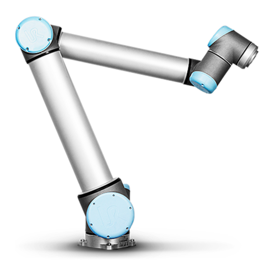
1.21. Begin programming 1.21.1. Introduction 13.1: Joints of the robot. A: Base, B: Shoulder, C: Elbow and D, E, F: Wrist 1, 2, 3 The Universal Robot arm is composed of tubes and joints. The joints with their usual names are shown in Figure 13.1. - Page 118 1. Unpack the robot arm and the control box. 2. Mount the robot on a sturdy surface strong enough to withstand at least 10 times the full torque of the base joint and at least 5 times the weight of the robot arm. The surface shall be vibration-free.
-
Page 119: The First Program
1.21.3. The First Program A program is a list of commands telling the robot what to do. PolyScope allows people with only little programming experience to program the robot. For most tasks, programming is done entirely using the touch panel without typing in any cryptic commands. Tool motion is the part of a robot program that teaches the Robot Arm how to move. -
Page 120: Polyscope Programming Interface
WARNING 1. Do not drive the robot into itself or anything else as this may cause damage to the robot. 2. Keep your head and torso outside the reach (workspace) of the robot. Do not place fingers where they can be caught. 3. -
Page 121: Welcome Screen
In this example, the Program tab is selected at the top level, and under that the Structure tab is selected. The Program tab holds information related to the currently loaded program. If the Move tab is selected, the screen changes to the Move screen, from where the robot arm can be moved. -
Page 122: Initialization Screen
1.21.6. Initialization Screen On this screen you control the initialization of the robot arm. Robot arm state indicator The status LED gives an indication of the robot arm’s running state: • A bright red LED indicates that the robot arm is currently in a stopped state where the reasons can be several. - Page 123 Similarly, the name of the installation file that is currently loaded is shown in the grey text field. A different installation can be loaded by tapping the text field or by using the Load button next to it. Alternatively, the loaded installation can be customized using the buttons next to the 3D view in the lower part of the screen.
- Page 124 UR10 User Manual...
-
Page 125: On-Screen Editors
1.22. On-screen Editors 1.22.1. On-screen Expression Editor While the expression itself is edited as text, the expression editor has a number of buttons and functions for inserting the special expression symbols, such as * for multiplication and ≤ for less than or equal to. - Page 126 Robot The current position of the robot arm and the specified new target position are shown in 3D graphics. The 3D drawing of the robot arm shows the current position of the robot arm, and the “shadow” of the robot arm shows the target position of the robot arm controlled by the specified values on the right hand side of the screen.
- Page 127 Feature and tool position In the top right corner of the screen, the feature selector can be found. The feature selector defines which feature to control the robot arm relative to Below the feature selector, the name of the currently active Tool Center Point (TCP) is displayed. see 1.23.6.
- Page 128 Cancel button Clicking the Cancel button leaves the screen discarding all changes. UR10 User Manual...
-
Page 129: Robot Control
1.23. Robot Control 1.23.1. Move Tab On this screen you can always move (jog) the robot arm directly, either by translating/rotating the robot tool, or by moving robot joints individually. Robot The current position of the robot arm is shown in 3D graphics. Push the magnifying glass icons to zoom in/out or drag a finger across to change the view. - Page 130 orientation boundary limit is visualized with a spherical cone together with a vector indicating the current orientation of the robot tool. The inside of the cone represents the allowed area for the tool orientation (vector). When the robot TCP no longer is in the proximity of the limit, the 3D representation disappears. If the TCP is in violation or very close to violating a boundary limit, the visualization of the limit turns red.
-
Page 131: I/O Tab
WARNING 1. Make sure to use the correct installation settings (e.g. Robot mounting angle, weight in TCP, TCP offset). Save and load the installation files along with the program. 2. Make sure that the TCP settings and the robot mounting settings are set correctly before operating the Freedrive button. -
Page 132: Modbus
Configurable outputs that are reserved for safety settings are not togglable and will be displayed as LED’s only. The electrical details of the signals are described in chapter 1.9.3. Controller I/O on page 30. Voltage In Tool Output, Voltage can be configured only when Tool Output is controlled by the User. Selecting a URCap removes access to the Voltage. -
Page 133: Automove Tab
1.23.4. AutoMove Tab The AutoMove tab is used when the robot arm has to move to a specific position in its workspace. Examples are when the robot arm has to move to the start position of a program before running it, or when moving to a waypoint while modifying a program. Animation The animation shows the movement the robot arm is about to perform. -
Page 134: Installation → Load/Save
Manual Pushing the Manual button will take you to the Move tab where the robot arm can be moved manually. This is only needed if the movement in the animation is not preferable. 1.23.5. Installation → Load/Save The Robot Installation covers all aspects of how the robot arm and control box are placed in the working environment. -
Page 135: Installation → Tcp Configuration
CAUTION Using the robot with an installation loaded from a USB drive is not recommended. To use an installation stored on a USB drive, first load it and then save it in the local programs folder using the Save As… button. 1.23.6. - Page 136 Adding, renaming, modifying and removing TCPs Tap the New button to define a new TCP. The created TCP automatically receives a unique name and becomes selectable in the drop-down menu. To rename a TCP, tap the Rename button. To remove the selected TCP, tap the Remove button. The last TCP cannot be removed. The translation and rotation of a selected TCP can be modified by entering new values into the fields.
- Page 137 1. Tap the TCP Position Wizard. 2. Choose a fixed point in the workspace of the robot. 3. Use the position arrows on the right side of the screen to move the TCP from at least three different angles and to save the corresponding positions of the tool output flange. 4.
-
Page 138: Installation → Mounting
Payload The weight of the robot’s tool is specified in the lower part of the screen. To change this setting, simply tap the white text field and enter a new weight. The setting applies to all defined TCPs. For details about the maximum allowed payload, see the Hardware Installation Manual. - Page 139 1. Making the Robot arm appear correctly on screen. 2. Telling the controller about the direction of gravity. An advanced dynamics model gives the Robot arm smooth and precise motions, as well as allows the Robot arm to hold itself in Freedrive Mode. For this reason, it is important to mount the Robot arm correctly.
-
Page 140: Installation → I/O Setup
1.23.8. Installation → I/O Setup On the I/O Setup screen, users can define I/O signals and configure actions with the I/O tab control. The Input and Output sections list types of I/O signals such as: • Digital standard general purpose, configurable and tool •... - Page 141 1. Select the desired signal 2. Tap the text field in the lower part of the screen to set the name. 3. To reset the name to default, tap Clear. A general purpose register must be given a user-defined name to make it available in the program (i.e., for a Wait command or the conditional expression of an If command) The Wait and If commands are described in (1.24.10.
-
Page 142: Installation → Safety
NOTE A program is terminated unscheduled if any of the following occur: • Protective stop • Fault • Violation • Runtime exception I/O Tab Control Specify whether an output is controlled on the I/O tab (by either programmers, or both operators and programmers), or if it is controlled by the robot programs. - Page 143 Installation variables names and values are stored with the installation, so you can use the same variable in multiple programs. Installation variables and their values are saved automatically every 10 minutes during program execution, also when the program is paused and when it is stopped. Creating a Variable 1.
-
Page 144: Installation → Modbus Client I/O Setup
1.23.11. Installation → MODBUS client I/O Setup Here, the MODBUS client (master) signals can be set up. Connections to MODBUS servers (or slaves) on specified IP addresses can be created with input/output signals (registers or digital). Each signal has a unique name so it can be used in programs. Refresh Push this button to refresh all MODBUS connections. - Page 145 Sequential mode Available only when Show Advanced Options (see Show Advanced Options on page 139) is selected. Selecting this checkbox forces the modbus client to wait for a response before sending the next request. This mode is required by some fieldbus units. Turning this option on may help when there are multiple signals, and increasing request frequency results in signal disconnects.
- Page 146 Set signal address This field shows the address on the remote MODBUS server. Use the on-screen keypad to choose a different address. Valid addresses depends on the manufacturer and configuration of the remote MODBUS unit. Set signal name Using the on-screen keyboard, the user can give the signal a name. This name is used when the signal is used in programs.
- Page 147 Show Advanced Options This check box shows/hides the advanced options for each signal. Advanced Options Update Frequency This menu can be used to change the update frequency of the signal. This means the frequency with which requests are sent to the remote MODBUS unit for either reading or writing the signal value.
-
Page 148: Installation → Features
1.23.12. Installation → Features A Feature represents an object defined by a six dimensional pose (position and orientation) relative to the robot base. You can name a feature for future reference. Some subparts of a robot program consist of movements executed relative to specific objects other than the base of the robot arm. - Page 149 15.1: Base feature 15.2: Tool (TCP) feature Use the Point feature, Line feature and/or Plane feature to define a feature pose. These features are positioned through a method that uses the current pose of the TCP in the work area. So you can teach feature locations using Freedrive , or "jogging" to move the robot to the desired pose.
- Page 150 configure with high precision. For more on adding features, see (sections: on the facing page), ( on page 144) and (Plane Feature on page 144). Using a feature You can refer to a feature defined the installation from the robot program, to relate robot movements (e.g. MoveL and MoveP commands) to the feature (see section 1.24.4.
- Page 151 Using Move here Tap Move here to move the robot arm towards the selected feature. At the end of this movement, the coordinate systems of the feature and the TCP will coincide. Point feature The point feature defines a safety boundary or a global home configuration of the Robot arm. The point feature pose is defined as the position and orientation of the TCP.
- Page 152 Adding a Line 1. In Installation, select Features. 2. Under Features select Line. 15.3: Definition of the line feature In figure 15.3 the axis directed from the first point towards the second point, constitutes the y- axis of the line coordinate system. The z-axis is defined by the projection of the z-axis of p1 onto the plane perpendicular to the line.
- Page 153 Adding a plane 1. In Installation, select Features. 2. Under Features select Plane. Teaching a plane When you press the plane button to create a new plane, the on-screen guide assists you creating a plane. 1. Select Origo 2. Move robot to define the direction of the positive x-axis of the plane 3.
- Page 154 MoveL # Feature: P1_var 15.4: Simple program with four waypoints relative to a feature plane manually updated by changing the feature The application requires the program to be reused for multiple robot installations where the position of the table varies slightly. The movement relative to the table is identical. By defining the table position as a feature P1 in the installation, the program with a MoveL command configured relative to the plane can be easily applied on additional robots by just updating the installation with the actual position of the table.
- Page 155 15.5: A MoveL command with four waypoints relative to a plane feature Robot Program MoveJ y = 0.01 o = p[0,y,0,0,0,0] P1_var = pose_trans(P1_var, o) MoveL # Feature: P1_var 15.6: Applying an offset to the plane feature Robot Program MoveJ if (digital_input[0]) then P1_var = P1 else P1_var = P2...
-
Page 156: Conveyor Tracking Setup
15.7: Switching from one plane feature to another The movement relative to P1 is repeated a number of times, each time by an offset o. In this example the offset is set to 10 cm in the Y-direction (see figure 15.6, offsets O1 and O2). This is achieved using pose_add() or pose_trans() script functions to manipulate the variable. -
Page 157: Smooth Transition Between Safety Modes
points that define the line feature. Configure the line feature by placing the tool firmly against the side of the conveyor when teaching the two points. If the line feature’s direction is opposite to the conveyor’s movement, use the Reverse direction button. The Ticks per meter field displays the number of ticks the encoder generates when the conveyor moves one meter. - Page 158 The Startup screen contains settings for automatically loading and starting a default program, and for auto-initializing the Robot arm during power up. WARNING 1. When autoload, auto start and auto initialize are enabled, the robot runs the program as soon as the Control Box is powered up as long as the input signal matches the selected signal level.
-
Page 159: Log Tab
Starting a Default Program The default program is auto started in the Run Program screen. When the default program is loaded and the specified external input signal edge transition is detected, the program is started automatically. On Startup, the current input signal level is undefined. Choosing a transition that matches the signal level on startup starts the program immediately. - Page 160 Robot Health The top half of the screen displays the "health" of the Robot Arm and Control Box. The left side of the screen shows information related to the Control Box, while the right side of the screen displays robot joint information. Each joint dsiplays the temperature of the motor and electronics, the load of the joint, and the voltage.
-
Page 161: Load Screen
1.23.17. Load Screen On this screen you choose which program to load. There are two versions of this screen: one that is to be used when you just want to load a program and execute it, and one that is used when you want to actually edit a program. -
Page 162: Path History
Path history The path history shows a list of the paths leading up to the present location. This means that all parent directories up to the root of the computer are shown. Here you will notice that you may not be able to access all the directories above the programs folder. -
Page 163: Run Tab
1.23.18. Run Tab This tab provides a very simple way of operating the robot arm and control box, with as few buttons and options as possible. This can be usefully combined with password protecting the programming part of PolyScope (see 1.25.3. Set Password on page 210), to make the robot into a tool that can run exclusively pre-written programs. - Page 164 UR10 User Manual...
-
Page 165: Programming
1.24. Programming 1.24.1. New Program A new robot program can start from either a template or from an existing (saved) robot program. A template can provide the overall program structure, so only the details of the program need to be filled in. User Manual UR10... -
Page 166: Program Tab
1.24.2. Program Tab The program tab shows the current program being edited. Program Tree The Program Tree on the left side of the screen displays the program as a list of commands, while the area on the right side of the screen displays information relating to the current command. - Page 167 Program Execution Indication The Program Tree contains visual cues informing about the command currently being executed by the robot controller. A small indicator icon is displayed to the left of the command icon, and the name of the executing command and any commands of which this command is a sub- command (typically identified by the / command icons) are highlighted with blue.
-
Page 168: Variables
Undo/Redo Buttons The buttons with icons in the toolbar at the base of the Program Tree serve to undo and redo changes made in the Program Tree and in the commands it contains. Program Dashboard The lowest part of the screen is the Dashboard. The Dashboard features a set of buttons similar to an old-fashioned tape recorder, from which programs can be started and stopped, single- stepped and restarted. -
Page 169: Command: Move
Installation variables These can be used by multiple programs and their names and values are persisted together (see 1.23.10. Installation → Variables on with the robot installation page 134). Installation variables keep their value after the robot and control box has been rebooted. Regular program variables These are available to the running program only and their values are lost as soon as the program is stopped. - Page 170 Movement Types You can select one of three types of movements: MoveJ, MoveL and MoveP. Each movement type is explained below. • moveJ makes movements that are calculated in the robot arm joint space. Each joint is controlled to reach the desired end location at the same time. This movement type results in a curved path for the tool.
- Page 171 Shared parameters The shared parameters in the bottom right corner of the Move screen apply to the movement from the previous position of the robot arm to the first waypoint under the command, and from there to each of the following waypoints. The Move command settings do not apply to the path going from the last waypoint under that Move command.
- Page 172 feature space of the selected feature. There are a few circumstances that need detailed explanation: The selected feature has no effect on relative waypoints. The relative movement is always performed with respect to orientation of the Base. When the robot arm moves to a variable waypoint, the Tool Center Point (TCP) is calculated as the coordinates of the variable in the space of the selected feature.
-
Page 173: Command: Fixed Waypoint
1.24.5. Command: Fixed Waypoint A point on the robot path. Waypoints are the most central part of a robot program, telling the robot arm where to be. A fixed position waypoint is taught by physically moving the robot arm to the position. -
Page 174: Example
Example Consider a pick and place application as an example (see figure 16.2), where the robot is currently at Waypoint 1 (WP_1) , and it needs to pick up an object at Waypoint 3 (WP_3) . To avoid collisions with the object and other obstacles (O) , the robot must approach (WP_3) in the direction coming from Waypoint 2 (WP_2) . -
Page 175: Conditional Blend Trajectories
WP_1 WP_2 WP_3 16.3: Blend over (WP_2) with radius r , initial blend position at p1 and final blend position at p2 . (O) is an obstacle. If a blend radius is set, the robot arm trajectory blends around the waypoint, allowing the robot arm not to stop at the point. -
Page 176: Trajectory Type Combinations
That means the if...then expression (or other necessary statements to determine the following waypoint, e.g. variable waypoints) is evaluated before we actually reach (WP_2) which is somewhat counter-intuitive when looking at the program sequence. If a waypoint is a stop point and followed by conditional expressions to determine the next waypoint (e.g. - Page 177 WP_2 WP_1 WP_3 WP_2 WP_1 WP_3 16.6: Joint space (MoveJ) vs. cartesian space (MoveL) movement and blend. Of the different combinations, bullets 2, 3 and 4 will result in trajectories that keep within the boundaries of the original trajectory in Cartesian space. An example of a blend between different trajectory types (bullet 2) can be seen in figure 16.7.
- Page 178 Pure joint space blends (bullet 1), however, may behave in a way that is less intuitive, since the robot will try to achieve the smoothest possible trajectory in Joint space taking velocities and time requirements into account. Due to this, they may deviate from the course specified by the waypoints.
-
Page 179: Command: Relative Waypoint
1.24.6. Command: Relative Waypoint A waypoint with the position given relative to the robot arm’s previous position, such as “two centimeters to the left”. The relative position is defined as the difference between the two given positions (left to right). Note: repeated relative positions can move the robot arm out of its workspace. -
Page 180: Command: Variable Waypoint
1.24.7. Command: Variable Waypoint A waypoint with the position given by a variable, in this case calculated_pos. The variable has to be a pose such as var=p[0.5,0.0,0.0,3.14,0.0,0.0]. The first three are x,y,z and the last three are the orientation given as a rotation vector given by the vector rx,ry,rz. -
Page 181: Command: Until
Stopping a Direction Movement You can add Direction Vector settings, for Tool Speed and Tool Acceleration, to define the vector direction for linear motion, allowing for advanced uses as: • defining linear motion relative to multiple feature axes • computing the direction as a mathematical expression The Direction Vectors defines a custom code expression that is resolved to a unit vector. - Page 182 In the Until field, you can define the following stop criteria: • Add Action Add program nodes if a specific until condition is met. For instance if an error state is detected, the program can be stopped with a Popup node. •...
-
Page 183: Command: Wait
1.24.10. Command: Wait Wait pauses I/O signal, or expression, for a given amount of time. If No Wait is selected, nothing is done. User Manual UR10... -
Page 184: Command: Set
1.24.11. Command: Set Sets either digital or analog outputs to a given value. Digital outputs can also be set to send a single pulse. Use the Set command to set the payload of the Robot Arm. You can adjust the payload weight to prevent the robot from triggering a protective stop, when the weight at the tool differs from the expected payload. -
Page 185: Command: Popup
1.24.12. Command: Popup The popup is a message that appears on the screen when the program reaches this command. You can select the message style and text by using the on-screen keyboard. Messages are limited to a maximum of 255 characters. The robot waits for the user/operator to press the OK button under the popup before continuing the program. -
Page 186: Command: Halt
1.24.13. Command: Halt The program execution stops at this point. UR10 User Manual... -
Page 187: Command: Comment
1.24.14. Command: Comment Gives the programmer an option to add a line of text to the program. This line of text does not do anything during program execution. User Manual UR10... -
Page 188: Command: Folder
1.24.15. Command: Folder A Folder is used to organize and label specific parts of a program, to clean up the program tree, and to make the program easier to read and navigate. Folders have no impact on the program and its execution. UR10 User Manual... -
Page 189: Command: Loop
1.24.16. Command: Loop Loops the underlying program commands. Depending on the selection, the underlying program commands are either looped infinitely, a certain number of times or as long as the given condition is true. When looping a certain number of times, a dedicated loop variable (called loop_1 in the screen shot above) is created, which can be used in expressions within the loop. - Page 190 Select conditions in the Expression Editor that make up expressions using an If statement. If a condition is evaluated as True, the statements within this If command are executed. An If statement can have only one Else statement. Use Add ElseIf and Remove ElseIf to add and remove ElseIf expressions.
-
Page 191: Command: Subprogram
1.24.18. Command: SubProgram A SubProgram can hold program parts that are needed several places. A SubProgram can be a separate file on the disk, and can also be hidden to protect against accidental changes to the SubProgram. User Manual UR10... - Page 192 Command: Call Subroutine A call to a Subroutine will run the program lines in the SubProgram, and then return to the following line. UR10 User Manual...
-
Page 193: Command: Assignment
1.24.19. Command: Assignment Assigns values to the variables. An assignment puts the computed value of the right hand side into the variable on the left hand side. This can be useful in complex programs. User Manual UR10... -
Page 194: Command: Script
1.24.20. Command: Script The following options are available in the drop down list under Command: • Line allows you to write a single line of URscript code, using the Expression Editor ( 1.22.1. On-screen Expression Editor on page 117) • File allows you to write, edit or load URscript files. You can find instructions for writing URscript in the Script Manual on the support website (http://www.universal-robots.com/support). -
Page 195: Command: Event
1.24.21. Command: Event An event can be used to monitor an input signal, and perform some action or set a variable when that input signal goes high. For example, in the event that an output signal goes high, the event program can wait for 200ms and then set it back to low again. -
Page 196: Command: Thread
1.24.22. Command: Thread A thread is a parallel process to the robot program. A thread can be used to control an external machine independently of the robot arm. A thread can communicate with the robot program with variables and output signals. UR10 User Manual... -
Page 197: Command: Switch
1.24.23. Command: Switch A Switch Case construction can make the robot change behavior based on sensor inputs or variable values. Use the Expression Editor to describe the base condition and define the cases under which the robot should proceed to the sub-commands of this Switch. If the condition is evaluated to match one of the cases, the lines inside the Case are executed. - Page 198 Timer A Timer measures the length of time it takes for specific parts of the program to run. A program variable contains the time passed since a Timer started, and can be seen in the Variables Tab and in the Run Tab. UR10 User Manual...
-
Page 199: Command: Pattern
1.24.24. Command: Pattern The Pattern command can be used to cycle through positions in the robot program. The Pattern command corresponds to one position at each execution. A pattern can be given as one of four types. The first three, Line, Square or Box can be used for positions in a regular pattern. -
Page 200: Command: Force
A Box pattern uses three vectors to define the side of the box. These three vectors are given as four points, where the first vector goes from point one to point two, the second vector goes from point two to point three, and the third vector goes from point three to point four. Each vector is divided by the interval count numbers. - Page 201 Force mode also supports applying certain torques around predefined axes. The robot arm attempts to accelerate along that axis, if no obstacles are met in an axis where a non-zero force is set. Although an axis is selected to be compliant, the robot program still tries to move the robot along that axis.
-
Page 202: Force Value Selection
Force mode type The types of force mode, listed below, determine how the selected feature is interpreted. • Simple: Only one axis will be compliant in force mode. The force along this axis is adjustable. The desired force will always be applied along the z-axis of the selected feature. -
Page 203: Limits Selection
1.24.27. Limits selection For all axes a limit can be set, but these have different meaning corresponding to the axes being compliant or non-compliant. • Compliant: The limit is the maximum speed the TCP is allowed to attain along/about the axis. -
Page 204: Command: Pallet
1.24.29. Command: Pallet A pallet operation can perform a sequence of motions in a set of places given as a pattern (see 1.24.24. Command: Pattern on page 191). At each of the positions in the pattern, the sequence of motions will be run relative to the pattern position. Programming a Pallet Operation 1. -
Page 205: Command: Seek
“BeforeStart” The optional BeforeStart sequence is run just before the operation starts. This can be used to wait for ready signals. “AfterEnd” The optional AfterEnd sequence is run when the operation is finished. This can be used to signal conveyor motion to start, preparing for the next pallet. 1.24.30. - Page 206 Stacking When stacking, the robot arm moves to the starting position, and then moves opposite the direction to search for the next stack position. When found, the robot remembers the position and performs the special sequence. The next time round, the robot starts the search from the remembered position incremented by the item thickness along the direction.
- Page 207 Destacking When destacking, the robot arm moves from the starting position in the given direction to search for the next item. The condition on the screen determines when the next item is reached. When the condition becomes satisfied, the robot remembers the position and performs the special sequence.
- Page 208 Direction The direction is given by two positions, and is calculated as the position difference from the first positions TCP to the second positions TCP. Note: A direction does not consider the orientations of the points. Next Stacking Position Expression The robot arm moves along the direction vector while continuously evaluating whether the next stack position has been reached.
-
Page 209: Command: Conveyor Tracking
Pick/Place Sequence The Pick/Place Sequence is a special program sequence performed at each stack position, similar to the Pallet operation (see 1.24.29. Command: Pallet on page 196). 1.24.31. Command: Conveyor Tracking NOTE Using this function at the same time as Force can lead to a program conflict. •... - Page 210 If the current position of the robot TCP comes close to a safety or trigger plane, or the orientation of robot tool is near the tool orientation boundary limit (see 1.20.12. Boundaries on page 97), a 3D representation of the boundary limit is shown. When the robot is running a program, the visualization of boundary limits will be disabled.
-
Page 211: Structure Tab
1.24.34. Structure Tab The program structure tab gives an opportunity for inserting, moving, copying and removing the various types of commands. To insert new commands, perform the following steps: 1. Select an existing program command. 2. Select whether the new command should be inserted above or below the selected command. -
Page 212: Variables Tab
1.24.35. Variables Tab The Variables tab shows the live values of variables in the running program, and keeps a list of variables and values between program runs. It only appears when it has information to display. The variables are ordered alphabetically by their names. The variable names on this screen are shown with at most 50 characters, and the values of the variables are shown with at most 500 characters. -
Page 213: Command: Variables Initialization
1.24.36. Command: Variables Initialization This screen allows setting variable values before the program (and any threads) start executing. Select a variable from the list of variables by clicking on it, or by using the variable selector box. For a selected variable, an expression can be entered that will be used to set the variable value at program start. - Page 214 UR10 User Manual...
-
Page 215: Setup Screen
1.25. Setup Screen • Initialize Robot Goes to the initialization screen, see 1.21.6. Initialization Screen on page 114. • Language and Units Configure the language and units of measurements for the user interface, see 1.25.1. Language and Units on the next page. • Update Robot Upgrades the robot software to a newer version, see 1.25.2. -
Page 216: Language And Units
1.25.1. Language and Units Language, units and keyboard language used in PolyScope can be selected on this screen. The selected language will be used for the text visible on the various screens of PolyScope as well as in the embedded help. Tick off “English programming” to have the names of commands within robot programs written in English. -
Page 217: Update Robot
1.25.2. Update Robot Software updates can be installed from USB flash memory. Insert an USB memory stick and click Search to list its contents. To perform an update, select a file, click Update, and follow the on- screen instructions. WARNING Always check your programs after a software upgrade. -
Page 218: Set Password
1.25.3. Set Password Two passwords are supported. The first is an optional System password which prevents unauthorized modification of the setup of the robot. When the System password is set, programs can be loaded and executed without the password, but the user must enter the correct password in order to create or change programs. -
Page 219: Calibrate Screen
1.25.4. Calibrate Screen Calibrating the touch screen. Follow the on-screen instructions to calibrate the touch screen. Preferably use a pointed non-metallic object, such as a closed pen. Patience and care help achieve a better result. User Manual UR10... -
Page 220: Setup Network
1.25.5. Setup Network Panel for setting up the Ethernet network. An Ethernet connection is not necessary for the basic robot functions, and is disabled by default. UR10 User Manual... -
Page 221: Set Time
1.25.6. Set Time Set the time and date for the system and configure the display formats for the clock. The clock is displayed at the top of the Run Program and Program Robot screens. Tapping on it will show the date briefly. -
Page 222: Urcaps Setup
1.25.7. URCaps Setup In the top list an overview of all installed URCaps is presented. Clicking on a URCap displays its meta information (including the name of the URCap, the version, license etc.) in the URCap Information area below the list. Click the + button in the bottom of the screen to install a new URCap. -
Page 223: Euromap 67 Interface
EUROMAP 67 Interface 1.26. Introduction This manual is intended for the integrator. It contains important information regarding integration, programming, understanding and debugging. Abbreviations used in this document are explained below. Abbreviation Meaning Universal Robots Controller Box Injection Moulding Machine User Manual UR10... -
Page 224: Euromap 67 Standard
EUROMAP 67 Interface Abbreviation Meaning Moulding Area Free A, B, C, ZA, ZB and ZC Signals inside EUROMAP 67 cable NOTE EUROMAP 67 is only supported on controller boxes produced after September 2014. WARNING An IMM can use up to 250V on some of its signals. Do not connect an IMM to the EUROMAP 67 interface if it is not properly installed in a controller box;... -
Page 225: Robot And Imm Integration
EUROMAP 67 Interface WARNING 1. An IMM is an extreamly dangerous machine. Read and understand the manual for the IMM. Failure to integrate the robot and IMM in a safe way might cause death, serious injury or damage to the machines. Universal Robots cannot be held responsible for any damage caused by an IMM (E.g. -
Page 226: Connecting A Maf Light Guard
EUROMAP 67 Interface 1.27.2. Connecting a MAF light guard The MAF signal [A3-C3] in the EUROMAP 67 cable enables the powerful movement of the mould. Care must be taken to prevent the mould from closing when the robot is inside the machine. The EUROMAP 67 interface is supplied without a MAF light guard. -
Page 227: Gui
EUROMAP 67 Interface some adaptors will not connect the UR robot and your IMM correctly. It is recommended to read both the EUROMAP 12 and EUROMAP 67 standard whenever using or constructing an adaptor. A list with common errors is shown below: 1. - Page 228 EUROMAP 67 Interface Selecting the EUROMAP 67 program template, the program screen will appear with the template loaded. The template structure will then be visible on the left side of the screen. UR10 User Manual...
-
Page 229: I/O Overview And Troubleshooting
EUROMAP 67 Interface The EUROMAP 67 program template is prepared for performing simple interaction with an IMM. By specifying only a few waypoints, and a pair of I/O actions, the robot is ready for handling the objects made by the IMM. The waypoints are: •... - Page 230 EUROMAP 67 Interface The (normal) state of the signals at startup, is that they are all low, except for the 24V signals, and the robot output Automatic Mode which is active-low and therefore set high per default. If a signal is not part of a program structure, and it is intended to be used in a robot program, this is achievable making use of e.g.
-
Page 231: Program Structure Functionality
EUROMAP 67 Interface 1.28.3. Program structure functionality There are seven program structures, which can be selected from the Structure tab on the program screen. These structures will be available after the eurompa67 interface has been properly installed (as explained in 1.29. Installing and uninstalling the interface on page 231). - Page 232 EUROMAP 67 Interface Startup Check Intended for use once in the beginning of a robot program, to make sure the robot and machine are set up correctly before moulding is started. Use the checkboxes to enable/disable individual steps. UR10 User Manual...
- Page 233 EUROMAP 67 Interface Free to Mould Used for signalling the IMM that it is allowed to start a moulding operation. When this signal is activated, the robot must be placed outside the IMM. Use the checkboxes to enable/disable individual steps. CAUTION When this signal is activated, the robot shall be outside the mould, so that the mould can close without touching the robot.
- Page 234 EUROMAP 67 Interface Wait for Item Intended for making the robot wait until an item is ready from the IMM. Use the checkboxes to enable/disable individual steps. UR10 User Manual...
- Page 235 EUROMAP 67 Interface Ejector Forward Enables the movement of the ejector which removes an item from the mould. Should be used when the robot is in position ready for grasping the item. Use the checkboxes to enable/disable individual steps. User Manual UR10...
- Page 236 EUROMAP 67 Interface Ejector Back Enables the movement of the ejector to its back position. Use the checkboxes to enable/disable individual steps. UR10 User Manual...
- Page 237 EUROMAP 67 Interface Core Pullers In Enables the movement of the core pullers to position 1. Which core pullers are used is selected from the drop down menu. Use the checkboxes to enable/disable individual steps. User Manual UR10...
-
Page 238: I/O Action And Wait
EUROMAP 67 Interface Core Pullers Out Enables the movement of the core pullers to position 2. Which core pullers are used is selected from the drop down menu. Use the checkboxes to enable/disable individual steps. 1.28.4. I/O action and wait As the robot digital outputs can be set by an Action node, so can also the EUROMAP 67 output signals. -
Page 239: Installing And Uninstalling The Interface
EUROMAP 67 Interface Finally, it is recommended to NOT set the Mould Area Free signal manually, as this may cause hazardous situations. 1.29. Installing and uninstalling the interface To achieve redundancy of the safety functionality, the controller box knows whether it shall expect a EUROMAP 67 interface to be present or not. -
Page 240: Uninstalling
EUROMAP 67 Interface • The interface is automatically detected. • The safety system of the robot reports that EUROMAP 67 is detected but not defined in the robot Installation. Go to Installation, Safety, and Miscellaneous and check the check-box Euromap67. •... -
Page 241: Maf Light Guard Interface
EUROMAP 67 Interface 1.30.1. MAF light guard interface The 24V is shared with the 24V [ZA9-ZC9] in the EUROMAP 67 cable. However, the input signals to the controller box are low current types and therefore most of the current is available. It is recommended to keep the load under 1.2A. -
Page 242: Digital Inputs
EUROMAP 67 Interface Parameter Unit [A1-C1][A2-C2][A3-C3] Current AC/DC 0.01 [A1-C1][A2-C2][A3-C3] Voltage DC [A1-C1][A2-C2][A3-C3] Voltage AC 1.30.3. Digital Inputs The digital inputs are implemented as pnp and are galvanically connected to the controller box. The inputs are compliant with all three types of digital inputs defined in IEC 61131-2 and EN 61131-2, which means that they will work together with all types of digital outputs defined in the same standards. -
Page 243: Glossary
2. Glossary 2. Glossary Stop Category 0 Robot motion is stopped by immediate removal of power to the robot. It is an uncontrolled stop, where the robot can deviate from the programmed path as each joint brake as fast as possible. This protective stop is used if a safety-related limit is exceeded or in case of a fault in the safety-related parts of the control system. -
Page 244: Index
2. Glossary Collaborative robot application The term collaborative refers to collaboration between operator and robot in a robot application. See precise definitions and descriptions in ISO 10218-1 and ISO 10218-2. Safety configuration Safety-related functions and interfaces are configurable through safety configuration parameters. These are defined through the software interface, see part Part II PolyScope Manual on page 85. - Page 245 2. Glossary Direction Vector 173 Ethernet 45 EtherNet/IP 132 Expression Editor 189 Feature 140, 148 Feature menu 193 Folder 180 Frame 194 Freedrive 131, 141, 195 General purpose I/O 31 I/O 29-30, 32, 113, 123, 132, 134 Installation 201 Installation variables 134 integrator 10 Joint load 152 User Manual...
- Page 246 2. Glossary joint space 162 Line pattern 191-192 List (pattern) 191 MODBUS 124, 136, 138, 148 Motion 194 Mounting bracket 1 Move 113, 142, 161, 163, 165, 176, 196 MoveJ 162 MoveL 142, 162 MoveP 142, 162 Normal mode 202 Pallet Sequence 196 Pattern 191-192 Point 194 PolyScope 1, 109, 111-112, 181...
- Page 247 2. Glossary Recovery mode 115 Relative waypoint 164 risk assessment 1, 5, 10-11 robot arm 134, 194, 198 Robot arm 29, 69, 152, 199 Safety Configuration 10 Safety I/O 31, 33 Safety instructions 49 Safety Settings 5 Script manual 2 Service manual 2 Set 176 Simple 194 Square pattern 191-192...
- Page 248 2. Glossary Until 172 Until Distance 174 Until Expression 174 UR+ 2 Variable feature 164 Variable waypoint 164 Variables 160, 204 Voltage 124 Wait 175 Warning signs 6 Warranty 55 Waypoint 161, 163, 165, 171, 196, 202 Waypoints 111 Wizards 201 Wrist 3 109 UR10 User Manual...
- Page 249 2. Glossary Software Version: 3.14 User Manual UR10...
Need help?
Do you have a question about the UR10/CB3 and is the answer not in the manual?
Questions and answers