Patton SmartNode 4110 Series User Manual
Voip gateway router
Hide thumbs
Also See for SmartNode 4110 Series:
- Quick start manual (13 pages) ,
- Quick start manual (12 pages)
Table of Contents
Advertisement
Quick Links
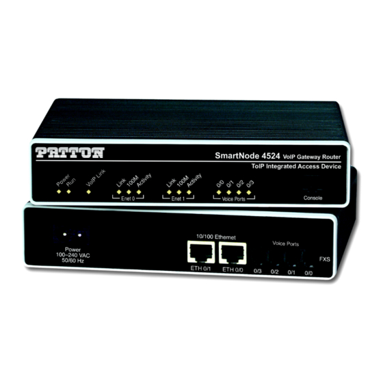
SmartNode 4520 & 4110 Series
VoIP Gateway Routers
User Manual
Important
This is a Class A device and is intended for use in a light industrial environment. It is not intended
nor approved for use in an industrial or residential environment.
Sales Office:
+1 (301) 975-1000
Technical Support:
+1 (301) 975-1007
E-mail:
support@patton.com
WWW:
www.patton.com
Part Number: 07MD4524-GS, Rev. J
Revised: August 3, 2015
Advertisement
Table of Contents


Need help?
Do you have a question about the SmartNode 4110 Series and is the answer not in the manual?
Questions and answers