Table of Contents
Advertisement
Quick Links
'
SmartNode 5540E and 4140E Series
Ruggedized Enterprise Session
Border Controller and VoIP Gateway
User Manual
This is a Class A device and is not intended for use in a residential environment.
REGULATORY MODEL NUMBER: 13260D4-001
Sales Office:
+1 (301) 975-1000
Technical Support:
+1 (301) 975-1007
E-mail:
support@patton.com
WWW:
www.patton.com
Part Number: 50000059 Rev. A
Revised: November 16, 2021
Advertisement
Table of Contents

Related Manuals for Patton SmartNode 5540E Series


Summary of Contents for Patton SmartNode 5540E Series
- Page 1 This is a Class A device and is not intended for use in a residential environment. REGULATORY MODEL NUMBER: 13260D4-001 Sales Office: +1 (301) 975-1000 Technical Support: +1 (301) 975-1007 E-mail: support@patton.com WWW: www.patton.com Part Number: 50000059 Rev. A Revised: November 16, 2021...
- Page 2 All other trademarks presented in this document are the property of their respective owners. Copyright © 2020–2021, Patton Electronics Company. All rights reserved. The information in this document is subject to change without notice. Patton Elec- tronics assumes no liability for errors that may appear in this document. Warranty Information The software described in this document is furnished under a license and may be used or copied only in accordance with the terms of such license.
-
Page 3: Table Of Contents
Initial Contacting Patton for Assistance ........................44 . -
Page 4: Table Of Contents
Placing the SmartNode device .........................31 Connecting cables ............................32 Installing an interface cable on the FXS and FXO interface ports ..............32 Connecting the 10/100/1000Base-T Ethernet LAN and WAN cables ............33 Connecting the power supply .........................34 Installing the Patton AC to DC power adapter ..................34... - Page 5 ........................44 Contacting Patton for Assistance Introduction ................................45 Contact information..............................45 Contacting Patton Technical Services for Free Support ...................45 Warranty Service and Returned Merchandise Authorizations (RMAs)..............45 Warranty coverage ............................45 Out-of-warranty service ..........................46...
- Page 6 SmartNode 5540E & 4140E Series User Manual Optional................................50 Capacity ................................50 Voice Signaling..............................50 Data Connectivity ..............................51 Voice Processing..............................51 Call Switching and Services ...........................51 FXS Connectivity ..............................52 Connectivity..............................52 Connectivity................................52 Quality of Service, SLA Assurance .........................52 Management .................................53 Physical .................................53 Safety & Compliance ............................53 .
- Page 7 SmartNode 5540E & 4140E Series User Manual 7. Notices ...............................76 8. Other Licenses ............................76 9. Unenforceable Provisions ..........................77 10. Governing Law ............................77 11. Waiver ..............................77...
-
Page 8: List Of Figures
Patton AC to DC power adapter ........ -
Page 9: List Of Tables
List of Tables General conventions ..............13 RJ-11 pins 3 and 4 . -
Page 10: About This Guide
5, starting on page 37, leads you through the steps to set up a new SmartNode device and down- • load a configuration • Chapter 6, starting on page 44, contains information on contacting Patton technical support for assistance • Appendix A, starting on page 47, provides compliance info for the SmartNode devices Appendix B, starting on page 49, contains specifications for the routers •... -
Page 11: Safety When Working With Electricity
CAUTION Safety when working with electricity The SmartNode device contains no user serviceable parts, and is not be opened by the user. The equipment shall be returned to Patton Electronics for repairs or repaired by qualified service personnel. WARNING Mains Voltage: In systems without a power switch, line voltages are present in the power supply when the power cord is connected. -
Page 12: Deutsch
SmartNode 5540E & 4140E Series User Manual Before handling the device, disconnect the telephone network cables to avoid contact with telephone line voltages. When detaching the cables, detach the end away from the SmartNode device first. WARNING Do not work on the system or connect or disconnect cables during periods of lightning activity. -
Page 13: General Observations
SmartNode 5540E & 4140E Series User Manual In Übereinstimmung mit den Anforderungen der Richtlinie 2002/96/EG über Elektro- und Elektronik-Altgeräte (WEEE) muss sichergestellt sein, dass Altgeräte von anderem Abfall und Schrott getrennt werden und dem Sammel- und Verwertungssystem für Elektro- und Elektronik-Altgeräte in Ihrem Land zum Recycling zugeführt werden. - Page 14 SmartNode 5540E & 4140E Series User Manual Table 1. General conventions (Continued) Convention Meaning node The leading IP address or nodename of a SmartNode is substituted with node in bold- face italic font. The leading SN on a command line represents the nodename of the SmartNode An hash sign at the beginning of a line indicates a comment line.
-
Page 15: Start
Chapter 1 SN5540E/SN4140E Series Quick Start Chapter contents Default IP Settings ..............................16 Default Login ................................16 Analog Port Pinout..............................16... -
Page 16: Default Ip Settings
You are responsible for creating a new administrator account to maintain system secu- rity. Patton Electronics accepts no responsibility for losses or damage caused by loss or misuse of passwords. Refer to Chapter 4 “Accessing the CLI” , section “Selecting a secure IMPORTANT password”... - Page 17 SmartNode 5540E & 4140E Series User Manual 1 • SN5540E/SN4140E Series Quick Start Figure 1. RJ-11 pin-outs Table 2. RJ-11 pins 3 and 4 Signal Ring (-) Tip (+) Analog Port Pinout...
-
Page 18: General Information
Chapter 2 General information Chapter contents SmartNode devices overview ..........................19 SmartNode 5540E Series eSBC/IAD ......................20 SmartNode 4140E Series VoIP Gateway ......................22... -
Page 19: Smartnode Devices Overview
Analog telephony to voice over IP (SIP) conversion for up to 8 FXS/FXO analog ports • • Fax T.38 and G711 bypass support Modem bypass support • Optional Patton Cloud network monitoring • • One Ethernet port for the SN4140E and two ports for the SN5540E and SN4141E/2ETH Stateful Firewall •... -
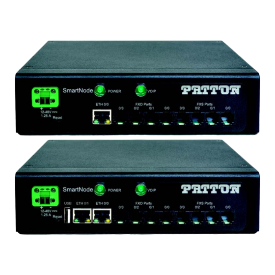
Page 20: Smartnode 5540E Series Esbc/Iad
3) and up to 200 SIP-to-SIP calls (non-transcoded). By default there are 4 SIP to SIP calls enabled. Additional calls can be enabled by loading SNSW-1B licenses (additional charge). The SmartNode 5540E Series LEDs, ports, and button are shown in figure 3... - Page 21 JS stands for FXS ports • JO stands for FXO ports • V stands for the number of VoIP calls • For a complete listing of available models, refer to the SmartNode VoIP page Note at https://www.patton.com/products/voip-comparison.asp. SmartNode devices overview...
-
Page 22: Smartnode 4140E Series Voip Gateway
SmartNode 5540E & 4140E Series User Manual 2 • General information SmartNode 4140E Series VoIP Gateway The SmartNode 4140E Series are compact VoIP Gateways that support 2 to 8 VoIP calls. The SmartNode 5540E Series LEDs, ports, and button are shown in figure 4 on page 23 and described in table... - Page 23 SmartNode 5540E & 4140E Series User Manual 2 • General information Figure 4. SN4140E LEDs, ports, and button SmartNode devices overview...
- Page 24 • JS stands for FXS ports JO stands for FXO ports • V stands for the number of VoIP calls • For a complete listing of available models, refer to the SmartNode VoIP page Note at https://www.patton.com/products/voip-comparison.asp. SmartNode devices overview...
-
Page 25: Applications Overview
Chapter 3 Applications overview Chapter contents Introduction ................................26 Application for SmartNode 5540E eSBC ......................26 Application for SmartNode 4140E VoIP Gateway ....................27... -
Page 26: Introduction
The unit can be vehicle-mounted and is suitable for military applications. Patton’s industrial VoIP gateway facilitates IP-based voice delivery for such applications as industrial automa- tion, military communications, railways, public transportation, public and private outdoor phones—including emergency phones in parking lots, along roadways and railways and within underground tunnels. -
Page 27: Application For Smartnode 4140E Voip Gateway
(see figure 6 on page 28). The major functions of the SmartNode 4140E VoIP Gateway are: • Optional Patton Cloud network monitoring • QoS (packet tagging) Number normalization and mapping • Fallback and survivability call routing to alternate SIP provider/IP-PBX •... -
Page 28: Sn4140E Application
SmartNode 5540E & 4140E Series User Manual 3 • Applications overview Figure 6. SN4140E application Application for SmartNode 4140E VoIP Gateway... -
Page 29: Installation
Installing an interface cable on the FXS and FXO interface ports ..............32 Connecting the 10/100/1000Base-T Ethernet LAN and WAN cables ............33 Connecting the power supply .........................34 Installing the Patton AC to DC power adapter ..................34 Installing the customer-provided DC power source ...................35... -
Page 30: Planning The Installation
31 to install the device. Site log Patton recommends that you maintain a site log to record all actions relevant to the system, if you do not already keep such a log. Site log entries should include information such as listed in table Table 5. -
Page 31: Software Tools
CLI. Power source Patton recommends that you include an uninterruptible power supply (UPS) in the installation to ensure that VoIP service is not impaired if the power fails. Installing the SmartNode device SmartNode device installation consists of the following: 1. -
Page 32: Connecting Cables
SmartNode 5540E & 4140E Series User Manual 4 • SmartNode Installation Connecting cables Do not work on the system or connect or disconnect cables during periods of lightning activity. WARNING The Interconnecting cables shall be acceptable for external use and shall be rated for the proper application with respect to voltage, current, anticipated temperature, flam- WARNING mability, and mechanical serviceability. -
Page 33: Connecting The 10/100/1000Base-T Ethernet Lan And Wan Cables
SmartNode 5540E & 4140E Series User Manual 4 • SmartNode Installation Figure 8. Analog FXS connection Figure 9. Analog FXO connection Table 6. RJ-11 socket Signal Ring (-) Tip (+) Connecting the 10/100/1000Base-T Ethernet LAN and WAN cables The SmartNode device has automatic MDX (auto-cross-over) detection and configuration on the Ethernet ports. -
Page 34: Connecting The Power Supply
“Port pin-outs” on page 58 for interface port pin-outs. Connecting the power supply If you are connecting a Patton AC to DC power adapter (part no. 2500005) to the SmartNode device, go to section “Installing the Patton AC to DC power adapter”. -
Page 35: Installing The Customer-Provided Dc Power Source
SmartNode 5540E & 4140E Series User Manual 4 • SmartNode Installation Figure 11. Power LED Congratulations, you have finished installing the SmartNode device! Now go to Chapter 5, “Initial Configura- tion” on page 37. Installing the customer-provided DC power source Do the following: Figure 12. - Page 36 SmartNode 5540E & 4140E Series User Manual 4 • SmartNode Installation 3. Insert the positive lead into the opening on the terminal block labeled + and the negative lead into the opening on the terminal block labeled -. 4. Tighten the screws on the block to secure the wires. 5.
-
Page 37: Configuration
Chapter 5 Initial Configuration Chapter contents Introduction ................................38 Connecting the SN5540E or SN4140E/2ETH to your laptop PC ................38 Configure the desired IP address ........................38 Factory-default IP Settings ........................38 Login ................................39 Changing the WAN IP address .........................39 Connecting the SmartNode device to the network ..................40 Connecting the SN4140E to a laptop PC......................41... -
Page 38: Configuration
SmartNode 5540E & 4140E Series User Manual 5 • Initial Configuration Introduction This chapter leads you through the basic steps to set up a new SmartNode device and to download a configuration. If you haven’t already installed the SmartNode device, refer to Chapter 4, Note "SmartNode Installation"... -
Page 39: Login
SmartNode 5540E & 4140E Series User Manual 5 • Initial Configuration DHCP server, the WAN interface uses DHCP client to automatically assign the IP address and network mask. Table 7. Factory Default IP Address and Network Mask Configuration IP Address Network Mask WAN Interface Ethernet 0 (ETH 0/0) DHCP... -
Page 40: Connecting The Smartnode Device To The Network
SmartNode 5540E & 4140E Series User Manual 5 • Initial Configuration Copy this modified configuration to you new start-up configuration. This will store your changes in non- volatile memory. Upon the next start-up the system will initialize itself using the modified configuration. The modified configuration is applied immediately. -
Page 41: Connecting The Sn4140E To A Laptop Pc
SmartNode 5540E & 4140E Series User Manual 5 • Initial Configuration Connecting the SN4140E to a laptop PC First, the SmartNode device must be connected to the main power supply with the power cable. Wait until the Power LED stops blinking and stays lit constantly. Now the SmartNode device is ready. The SmartNode device has a fixed IP and a DHCP client setup to simplify Note configuration. -
Page 42: Configure The Desired Ip Address
SmartNode 5540E & 4140E Series User Manual 5 • Initial Configuration You can check the connection to the SmartNode by executing the ping command from the PC command win- dow as follows: ping 192.168.200.10 Configure the Desired IP Address Factory-default IP Settings 7. -
Page 43: Loading The Configuration (Optional)
Loading the Configuration (optional) WebWizard Community provides a collection of Wizards that help to reduce the setup time of a Patton device. Simply download the appropriate Wizard to your device, execute it locally, and you are ready to do phone calls after the SmartNode has rebooted. -
Page 44: Contacting Patton For Assistance
Chapter 6 Contacting Patton for Assistance Chapter contents Introduction ................................45 Contact information..............................45 Contacting Patton Technical Services for Free Support ...................45 Warranty Service and Returned Merchandise Authorizations (RMAs)..............45 Warranty coverage ............................45 Out-of-warranty service ..........................46 Returns for credit ............................46 Return for credit policy ..........................46... -
Page 45: Introduction
(RMA). Contact information Patton Electronics offers a wide array of free technical services. If you have questions about any of our other products we recommend you begin your search for answers by using our technical knowledge base. Here, we have gathered together many of the more commonly asked questions and compiled them into a searchable database to help you quickly solve your problems. -
Page 46: Out-Of-Warranty Service
RMA#: xxxx 7622 Rickenbacker Dr. Gaithersburg, MD 20879-4773 USA Patton will ship the equipment back to you in the same manner you ship it to us. Patton will pay the return shipping costs. Warranty Service and Returned Merchandise Authorizations (RMAs) -
Page 47: A Compliance Information
Appendix A Compliance Information Chapter contents Compliance ................................48 EMC compliance ............................48 Safety compliance ............................48 CE compliance ..............................48 EC Declaration of Conformity ..........................48 Authorized European Representative ........................48... -
Page 48: Compliance
SmartNode 5540E & 4140E Series User Manual A • Compliance Information Compliance EMC compliance EN55032 and EN55024 Safety compliance EN62368-1 CE compliance FCC Part 15 Class A • • RoHS Compliant EC Declaration of Conformity We certify that the apparatus identified above conforms to the requirements of Council Directive 2014/30/EU on the approximation of the laws of the member states relating to electromagnetic compatibility;... -
Page 49: B Specifications
Appendix B Specifications Chapter contents Power Input ................................50 Optional Power Input ............................50 Mounting ................................50 Enclosure................................50 Vibration................................50 Shock ..................................50 Electrical Protection ..............................50 Optional................................50 Capacity ................................50 Voice Signaling..............................50 Data Connectivity ..............................51 Voice Processing..............................51 Call Switching and Services ...........................51 FXS Connectivity ..............................52 Connectivity..............................52 Connectivity................................52 Quality of Service, SLA Assurance .........................52... -
Page 50: Power Input
SmartNode 5540E & 4140E Series User Manual B • Specifications Refer to the software feature matrix for the most up-to-date specifications. Note Power Input Terminal block, 12–48 VDC nominal Two screws fasten the plug to the enclosure to lessen the chance of yanking it loose. Optional extended temperature external AC to DC power adapter is avail- Note able for extra charge. -
Page 51: Data Connectivity
SmartNode 5540E & 4140E Series User Manual B • Specifications Multi instance, simultaneous support of multiple registrars and direct IP dialing) DTMF in-band & out-of-band Localization - All tones programmable (dial, ringing, busy) B2BUA—eSBC capable** Data Connectivity Two 10/100/1000Base-TX Ethernet ports (SN5540E; SN4140E/2ETH) One 10/100/1000Base-TX Ethernet port (SN4140E) All ports full duplex, auto-sensing, auto-MDX Voice Processing... -
Page 52: Fxs Connectivity
IPv4 & IPv6 dual stack ICMP DNS, DynDNS SNTP Client Quality of Service, SLA Assurance Patton Cloud based Call Quality Monitoring & Alerting Voice priority, DownStreamQoS™ Traffic Management, shaping policing iEEE 802.1p, IEEE 802.1Q, 4096 VLANs (Tag insertion/deletion), TOS, DiffServ Labeling FXS Connectivity... -
Page 53: Management
SmartNode 5540E & 4140E Series User Manual B • Specifications Management Patton Cloud Orchestrated, Advanced CDRs and Call Quality Metrics** Customizable WebWizard, Webbased GUI HTTP/HTTPS access, CLI Telnet / SSH Secure Auto-Provisioning (Zero Touch) with built in root CA Separate config domain (LAN side config and WAN side config) TR-069 (CWMP-ACS), TFTP, HTTP, HTTPS configuration &... -
Page 54: C Cabling
Appendix C Cabling Chapter contents Introduction ................................55 Ethernet ................................55 Analog FXS ................................56 Analog FXO ................................57... -
Page 55: Introduction
SmartNode 5540E & 4140E Series User Manual C • Cabling Introduction This section provides information on the cables used to connect the SmartNode device to the existing network infrastructure and to third party products. Ethernet Ethernet devices (10/100/1000 Base-T) are connected to the SmartNode over a cable with RJ-45 plugs. All Ethernet ports on the SmartNode device are Auto-MDX. -
Page 56: Analog Fxs
SmartNode 5540E & 4140E Series User Manual C • Cabling Figure 18. Typical Ethernet straight-through cable diagram for 1000Base-T Analog FXS The Interconnecting cables shall be acceptable for external use and shall be rated for the proper application with respect to volt- age, current, anticipated temperature, flammability, and CAUTION mechanical serviceability. -
Page 57: Analog Fxo
SmartNode 5540E & 4140E Series User Manual C • Cabling Analog FXO The Interconnecting cables shall be acceptable for external use and shall be rated for the proper application with respect to volt- age, current, anticipated temperature, flammability, and CAUTION mechanical serviceability. -
Page 58: D Port Pin-Outs
Appendix D Port pin-outs Chapter contents Introduction ................................59 Ethernet ................................59 port................................59 FXO port ................................60... -
Page 59: D Port Pin-Outs
SmartNode 5540E & 4140E Series User Manual D • Port pin-outs Introduction This section provides pin-out information for the ports of the SmartNode. Ethernet Table 9. 10/100 Base-T RJ-45 socket Signal Pins not listed are not used. Note Table 10. 1000Base-T RJ-45 Socket Signal TRD0+ TRD0-... -
Page 60: Fxo Port
SmartNode 5540E & 4140E Series User Manual D • Port pin-outs Figure 21. RJ-11 pinout diagram FXO port The FXO ports use an RJ-11 connector with 6 positions. The middle two positions 3 and 4 are used according table Table 12. RJ-11 socket Signal Ring (-) Tip (+) -
Page 61: E Smartnode Device Factory Configuration
Appendix E SmartNode Device Factory Configuration Chapter contents Introduction ................................62... -
Page 62: Introduction
SmartNode 5540E & 4140E Series User Manual E • SmartNode Device Factory Configuration Introduction Factory configuration settings for the SmartNode device can be obtained with the following command through the CLI; login: admin password: <Enter> 192.168.1.1>show config:shipping-config See Chapter 5, "Initial Configuration"... -
Page 63: F Reset Button Functions
Appendix F Reset Button Functions Chapter contents Introduction ................................64 Resetting the SmartNode device when it is operating and the POWER LED is lit ..........65 Very exceptional case—minimal config recovery ....................66... -
Page 64: Introduction
SmartNode 5540E & 4140E Series User Manual F • Reset Button Functions Introduction The Reset button (see figure 22 for the SN4140E or figure 23 on page 65 for the SN5540E) is used to do the following: • Reboot the SmartNode device (see section “Resetting the SmartNode device when it is operating and the POWER LED is lit”... -
Page 65: Resetting The Smartnode Device When It Is Operating And The Power Led Is Lit
SmartNode 5540E & 4140E Series User Manual F • Reset Button Functions Figure 23. SN5540E Reset button Resetting the SmartNode device when it is operating and the POWER LED is lit The Reset button has the following behaviors depending on how many seconds (see figure 24) the button is pressed (see... -
Page 66: Very Exceptional Case-Minimal Config Recovery
65, the SmartNode device is still not operational, the following may remedy the problem by erasing the entire contents of flash memory (no exceptions). However it is recommended that in such a case the device be sent to Patton for analysis and repair. See section “Warranty Service and Returned Merchandise Authorizations (RMAs)”... -
Page 67: Using The Reset Button To Switch To A Backup Image
SmartNode 5540E & 4140E Series User Manual F • Reset Button Functions 2. The POWER LED will begin a series of blink pattern starting with 1-blink, pause. Table 14. Using the Reset button to switch to a backup image LED Blink Pattern Action 1-blink, pause Boot normally... -
Page 68: G Installing Optional Rack Ears
Appendix G Installing Optional Rack Ears Chapter contents Installing the rack ears ............................69... -
Page 69: Installing The Rack Ears
SmartNode 5540E & 4140E Series User Manual G • Installing Optional Rack Ears Installing the rack ears Do the following: 1. While holding the rack ear in place where shown in figure 25, use a cross-tip screwdriver to install three mounting screws (included with the rack ears kit) to secure the rack ear. -
Page 70: H Installing Optional Din Rail Mounting Clip
Appendix H Installing Optional DIN Rail Mounting Clip Chapter contents DIN rail mounting clip installation ........................71 Attaching the SmartNode device to a DIN rail using the mounting clip..............71... -
Page 71: Din Rail Mounting Clip Installation
SmartNode 5540E & 4140E Series User Manual H • Installing Optional DIN Rail Mounting Clip DIN rail mounting clip installation 1. With the SmartNode device oriented top side up, place the mounting clip as shown figure 2. Using a cross-tip screwdriver, install the two mounting screws (included with the DIN rail mounting clip kit) to secure the clip. -
Page 72: Mounting Clip Oriented For Installation On Din Rail
SmartNode 5540E & 4140E Series User Manual H • Installing Optional DIN Rail Mounting Clip Figure 27. Mounting clip oriented for installation on DIN rail 2. The SmartNode device can be attached to top hat NS 35/7.5 (35 H × 7.5 D mm) and NS 35/15 (35 H × 15 D mm) section types of DIN rail (see figure 28). -
Page 73: Installing The Device Onto The Din Rail
SmartNode 5540E & 4140E Series User Manual H • Installing Optional DIN Rail Mounting Clip Figure 29. Installing the device onto the DIN rail 3. Rotate the device until the lower DIN rail lip snaps into the lower DIN rail clip slot (see callout 2 on figure 29). -
Page 74: I End User License Agreement
Appendix I End User License Agreement Chapter contents End User License Agreement ..........................75 1. Definitions ..............................75 2. Title ................................75 3. Term ................................75 4. Grant of License ............................75 5. Warranty ..............................76 6. Termination ..............................76 7. Notices ...............................76 8. Other Licenses ............................76 9. -
Page 75: End User License Agreement
End User agrees to the following conditions: 1. Definitions “Effective Date” shall mean the earliest date of purchase or download of a product containing the Patton Electronics Company Program(s) or the Program(s) themselves. “Program(s)” shall mean all software, software documentation, source code, object code, or executable code. -
Page 76: Warranty
Program(s), even if Patton Electronics Company has been advised of the possi- bility of such damages. Because some states do not allow the exclusion or limitation of liability for consequen- tial or incidental damages, the above limitation may not apply to you. -
Page 77: Unenforceable Provisions
State of Maryland, USA for any dispute arising under or relating to this agreement and waives user’s right to institute legal proceedings in any other jurisdiction. Patton shall be entitled to institute legal proceedings in connection with any matter arising under this agreement in any juris- diction where User resides, does business, or has assets.
Need help?
Do you have a question about the SmartNode 5540E Series and is the answer not in the manual?
Questions and answers