Table of Contents
Advertisement
Quick Links
Advertisement
Table of Contents

Related Manuals for CKD RCS2 Series


Summary of Contents for CKD RCS2 Series
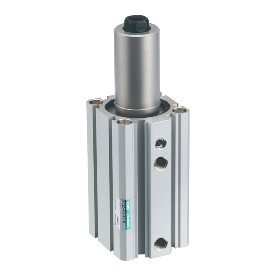
- Page 1 Rotary Clamp Cylinder (Single Guide) RCS2 Series (φ12~φ63) INSTRUCTION MANUAL 取扱説明書 SM-T000001-A SM-358642 • Read this Instruction Manual before using the product. • Read the safety notes carefully. • Keep this Instruction Manual in a safe and convenient place for future reference.
-
Page 2: Preface
• Since there are a wide variety of customer applications, it is impossible for CKD to be aware of all of them. Depending on the application or usage, the product may not be able to exercise its full performance or an accident may occur due to fluid, piping, or other conditions. -
Page 3: Safety Information
SM-T000001-A SAFETY INFORMATION SAFETY INFORMATION When designing and manufacturing any device incorporating the product, the manufacturer has an obligation to ensure that the device is safe. To that end, make sure that the safety of the machine mechanism of the device, fluid control circuit, and the electric system that controls such mechanism is ensured. -
Page 4: Table Of Contents
SM-T000001-A CONTENTS CONTENTS PREFACE ........................... i SAFETY INFORMATION ....................ii CONTENTS ........................iii PRODUCT OVERVIEW ..................1 Model Number Indication ..................1 1.1.1 Product model number .................. 1 1.1.2 Part model number ..................2 Specifications ...................... 3 1.2.1 Product Specification ..................3 1.2.2 Switch specifications .................. -
Page 5: Product Overview
1. PRODUCT OVERVIEW 1.1 Model Number Indication 1.1.1 Product model number Example of model number indication <Standard type> <Packing material fluoro rubber type> <Anti-spatter adherence prevention type> (A)Model No. (B)Mounting (C) Bore size (D)Port thread φ12 RCS2 Standard type Basic Rc thread Blank... -
Page 6: Part Model Number
(G)Switch model No. Voltage Bore size Lead wire Lead wire Contact Display Lead wire Straight L-shaped ● ● ● ● ● ● ● ● ● ● 1-color display T0H※ T0V※ ● ● ● ● ● ● ● ● ● ● T5H※... -
Page 7: Specifications
1.2 Specifications 1.2.1 Product Specification RCS2 (Standard type) Descriptions RCS2 φ12 φ16 φ20 φ25 φ32 φ40 φ50 φ63 Bore size Actuation Double acting Working fluid Compressed air Max. working pressure (Note 1) Min. working pressure Proof pressure ℃ Ambient temperature -10~60 (no freezing ) Rc1/8 Rc1/4... - Page 8 RCS2-G4 (Anti-spatter adherence) Descriptions RCS2-G4 φ32 φ40 φ50 φ63 Bore size Actuation Double acting Working fluid Compressed air Max. working pressure (Note 1) Min. working pressure Proof pressure ℃ Ambient temperature -10~60 (no freezing ) Rc1/8 Rc1/4 Port size NPT1/8 NPT1/4 G1/8...
-
Page 9: Switch Specifications
1.2.2 Switch specifications Reed 2-wire (T switch) Reed 2-wire Descriptions T0H/T0V T5H/T5V T8H/T8V For programmable controller, For programmable relay, IC circuit Applications For programmable controller, relay controller, relay (without indicator), serial connection Load voltage 12/24 VDC 110 VAC 5/12/24 VDC 100/110 VAC 12/24 VDC 110 VAC... - Page 10 Proximity 3-wire (T switch) Proximity 3-wire Descriptions T3PH/T3PV T3YH/T3YV T3WH/T3WV T3H/T3V (PNP output) (2-color display) (2-color display) Applications For programmable controller, relay Output method NPN output PNP output NPN output Power supply voltage 10 to 28 VDC Load voltage 30 VDC or less Load current 100 mA or less...
- Page 11 (Proximity 2-wire) (F switch) Proximity switch Descriptions F2H/F2V F2YH/F2YV Applications Dedicated for programmable controller Load voltage 10 to 30 VDC 24 VDC ±10% (Note1) Load current 5 to 20 mA Internal voltage drop 4 V or less Indicator lamp Yellow LED (Lit when ON) Yellow LED (Lit when ON) Red/green LED (Lit when ON)
-
Page 12: Installation
2. INSTALLATION 2.1 Environment • Use the product within the following ambient temperature ranges: −10°C to 60°C (no freezing) RCS2 (standard type) RCS2-T2 (low hydraulic type) 5°C to 50°C RCS2-G4 (heat-resistant type) 5°C to 120°C • For compressed air, use clean and dry air that has been passed through an air filter. Use an air filter in the circuit and be careful with the filtration rate (a filter that removes particles exceeding 5 μm is desirable), flow rate, and mounting position (install the filter near the directional control valve). -
Page 13: Mounting
2.3 Mounting 2.3.1 Cylinder installation • This product, use mounting hokes of four through holes, screws and flange provided in the main body part, and install it vertically with bolts. CAUTION Do not apply rotational torque to the piston rod when attaching or detaching the clamp lever. -
Page 14: Mounting The Switch
2.3.2 Mounting the switch Mounting position <Mounting the switch at the end of the stroke> In order to operate the switch at the maximum sensitivity position, install the switch at the position of RD dimension and HD dimension shown below. Also, please install the switch so that the lead wire is inside as shown below。... - Page 15 Operating range and hysteresis The mounting position, operating range, hysteresis (Unit:mm) Proximity switch Proximity switch Proximity switch (T2,T3T3P) (T2J) (T2W,T3W) Bore size (mm) Operating range Operating range Operating range Hysteretic Hysteretic Hysteretic (reference value) (reference value) (reference value) φ12 1.5~5.5 10.5 3~6...
-
Page 16: Piping
2.4 Piping 2.4.1 Basic circuit In order to operate normally, follow the basic items below and make the circuit as shown below. Double acting cylinder Solenoid valve (Direction switching valve) Compressed air Air filter + Regulator + Pressure gauge Speed controller Silencer 2.4.2 Piping... - Page 17 • Use a seal tape or a seal material to stop leakage from piping. Apply a seal tape or seal material to the screw threads leaving two or more threads at the pipe end uncovered or uncoated. If the pipe end is fully covered or coated, a shred of tape or residue of seal material may enter inside of the pipes or device and cause a failure.
-
Page 18: Wiring
2.5 Wiring 2.5.1 Reed switch Connection of lead wires Do not connect the lead wire of the switch to the power directly. Make sure that the lead wire and the load are connected in serial. For T0 and T8, observe the following instructions as well: •... - Page 19 <Protection when the wiring length exceeds the value shown in the table above> Blue Blue Brown Brown Within 2 m Switch Switch Within 2 m Applied Applied voltage voltage Load Load - Choke coil - Starting current restriction resistor L = Several hundred µH to several mH R = Highest possible resistance for the load circuit Excellent high frequency characteristic - Wire near the switch (within 2 m).
-
Page 20: Proximity Switch (T Type)
2.5.2 Proximity switch (T type) Connection of lead wires Turn off the power to the device in the electric circuit to which the switch is to be connected and connect the lead wires according to their color. If the switch is not wired correctly or the load is short-circuited, it may cause damage not only to the switch but also to the electric circuit on the load side. - Page 21 Within 2m Ex. 5 - Power supply noise absorption circuit =20 μF to 50 μF electrolytic capacitor Brown (withstand voltage 50V or more) =0.01 μF to 0.1 μF ceramic capacitor + =20 Ω to 30 Ω Black - Starting current restriction resistor Switch = Highest possible resistance for the load circuit.
- Page 22 Parallel connection Since the leakage current of a 2-wire type switch increases according to the number of connected units, check the input specifications of the programmable controller, which is a connected load, to determine the number of switches to connect. For the 2-wire type switch, the indicator may become dim or not light up. Although the leakage current of a 3-wire type switch increases according to the number of connected units, the leakage current is very small (10 μA or less) and can generally be ignored.
-
Page 23: Proximity Switch (F Type)
2.5.3 Proximity switch (F type) Connection of lead wires Turn off the power to the device in the electric circuit to which the switch is to be connected and connect the lead wires according to their color. If the switch is not wired correctly or the load is short-circuited, it may cause damage not only to the switch but also to the electric circuit on the load side. - Page 24 Within 2m Ex. 10 - Power supply noise absorption circuit =20 μF to 50 μF electrolytic capacitor Brown (withstand voltage 50V or more) =0.01 μF to 0.1 μF ceramic capacitor + =20 Ω to 30 Ω Black - Starting current restriction resistor Switch = Highest possible resistance for the load circuit.
- Page 25 Parallel connection Since the leakage current of a F2 and F2Y type switches increases according to the number of connected units, check the input specifications of the programmable controller, which is a connected load, to determine the number of switches to connect. For the F2 and F2Y type switch, the indicator may become dim or not light Although the leakage current of a F3 and F3Y type switch increases according to the number of connected units, the leakage current is very small (10 μA or less) and can generally be ignored.
-
Page 26: Usage
3. USAGE 3.1 Using the cylinder Clamp lever allowable length and working pressure The upper limit of the clamp lever’s allowable length differs depending on the working pressure. Set it to within the range shown below. <Clamp lever allowable length> Lever length Working range Working pressure (MPa) - Page 27 Moment of inertia calculation When rotary shaft passes through the workpiece...
- Page 28 Precautions for operation WARNING When rotating, make sure that the clamp lever mounted to the piston rod end does not interfere with the exterior while rotating. If the rotation of the clamp lever could cause bodily injury, be sure to provide safety measures by installing a protective cover, etc. to clamp lever’s surroundings.
- Page 29 Do not clamp the product in the rotational direction. Do not use as a stopper. Do not clamp the inclined portion.
- Page 30 Do not move the workpiece with exterior power. Do not install horizontally.
-
Page 31: Using The Switch
3.2 Using the switch Magnetic environment Do not use the switch in a place where there is a strong magnetic field or large current (such as a large magnet or welding machine). Magnetic material such as iron plate nearby cylinder switch is apt to cause malfunction of cylinder switches. Keep it from cylinder surface at least 10 mm away. -
Page 32: Maintenance And Inspection
4. MAINTENANCE AND INSPECTION CAUTION Release the residual pressure and make sure that there is no residual pressure before disassembling or inspecting the actuator. Turn off the power before disassembling or inspecting the actuator. Do not touch electrical wiring connections (bare live parts) of actuators equipped with solenoid valves, actuators equipped with switches, and other such actuators. -
Page 33: Disassembling And Assembling
4.2 Disassembling and Assembling Follow the procedure below to perform maintenance and repairs when a problem such as an air leakage occurs. 4.2.1 How to disassembly Using a hexagonal wrench, Loosen the hexagon socket set screw next to the rod side port and remove Hexagon socket set screw Use the snap ring pliers (for holes) to remove the C-ring (for Ø12, 16 is R-ring). - Page 34 Remove the rod metal assembly. When Ø12, 16, 40, 50, 63 are pulled toward the rod side. When Ø20, 25, 32 are pushed toward the head side, the rod metal assembly including the piston rod assembly will come off. At this time, the rod metal assembly and the piston rod assembly disengage at the same time.
-
Page 35: Inspection Of Parts
Piston rod assembly will come off from rod metal assembly. 4.2.2 Inspection of parts Perform the parts inspection of the following items. • Scratches on the inner surface of the tube. • Scratches on the piston rod surface, delamination of metal surface treatment, rust. •... -
Page 36: Assembly
4.2.3 Assembly Attention to the following items and reassemble by the reverse procedure at disassembly. • Apply thinly high quality grease (Lithium soap based grease of consistency 2) to the inner surface of the main body, the outer circumferential surface of the piston, the outer circumferential surface of the piston rod, the lead groove of the piston rod and entire the packing of the sliding portion. -
Page 37: Internal Structure And Consumable Parts
4.2.4 Internal structure and consumable parts RCS2-12, 16 / RCS2-T2-12, 16 For RCS2-T2-12,16 materials of 2, 5, 8 and 14 are changed to fluoro rubber. RCS2-20, 25 / RCS2-T2-20, 25 For RCS2-T2-20,25 materials of 3, 6, 9, 14 and 17 are changed to fluoro rubber. Consumable parts list Packing kit For RCS2... - Page 38 RCS2-32 / RCS2-T2-32 For RCS2-T2-32 materials of 3, 6, 9, 15 and 17 are changed to fluoro rubber. RCS2-40, 50, 63 / RCS2-T2-40, 50, 63 For RCS2-T2-40,50,63 materials of 3, 6, 9, 15 are changed to fluoro rubber. Consumable parts list Packing kit For RCS2...
- Page 39 RCS2-G4-32 RCS2-G4-40, 50, 63 Consumable parts list Packing kit (Same as for RCS2 standard) Bore size For RCS2-G4 Consumable part number φ32 RCS2-32K 2, 5, 8, 11, 12, 17, 18, 19 φ40 RCS2-40K φ50 RCS2-50K 2, 5, 7, 10, 11, 16, 17 φ63 RCS2-63K Guide pin kit...
-
Page 40: Troubleshooting
5. TROUBLESHOOTING 5.1 Problems, Causes and Solutions 5.1.1 Cylinder If the cylinder does not operate properly, check the table below for a possible solution. Problem Cause Solution Insufficient pressure. Confirm supply pressure to cylinder. Cylinder does not No signal in the directional control valve. Check the control circuit. -
Page 41: Switch
5.1.2 Switch If the switch does not operate properly, check the table below for a possible solution. Problem Cause Solution Contact is welded. Replace the switch. Replace with recommended relay or replace Switch turns on but Rating of load is exceeded. indicator does not switch. -
Page 42: Warranty
6. WARRANTY 6.1 Warranty conditions Warranty scope In the even of a failure that is clearly recognized as our responsibility during the following warranty period, we will provide alternative products of this product, necessary replacement parts, or repair at our factory without charge.
Need help?
Do you have a question about the RCS2 Series and is the answer not in the manual?
Questions and answers