
Related Manuals for CKD EVD Series


Summary of Contents for CKD EVD Series
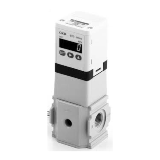
- Page 1 New product Compact high-function digital control Digital electro pneumatic regulator EVD series CC-764A...
- Page 2 The easy-to-use highly functional compact EVD Series digital electropneumatic regulator features a variety of new functions including pressure display, error display, and direct memory. User-friendly, outstanding installation performance Realizing high-level functions with microcomputer The digital display shows control status at a glance.
- Page 3 Example of proportional pressure controls Fluid discharge rate control Tension control using air brake Magnetic tape Air brakes E V D Tank Fluid pressure control Balancer tension control Grinding force control Controller Controller Cylinder Regulator for large flow rate Solenoid valve Nozzle Grindstone Air pump...
-
Page 4: Safety Precautions
Use this product in accordance of specifications. Contact CKD when using the product outside the unique specifications range, when using it outdoors, and when using it under the conditions and environment below. Do not attempt to modify or additionally machine the product. -
Page 5: Design & Selection
Pneumatic components (digital electro pneumatic regulator) Safety precautions Always read this section before starting use. Design & Selection WARNING Response is affected by the working pressure and load volume. If repeatability with stable response is Thoroughly understand the characteristics of com- required, install a regulator before the product. -
Page 6: Installation And Adjustment
Avoid using this regulator where it will be subject to direct Confirm that primary pressure does not drop to less sunlight, water or oil, etc. Consult with CKD when using than "set secondary pressure + maximum control outside designated specifications or for special applications. - Page 7 Series Installation & Adjustment The D-sub connector's rotator is not designed for The D-sub connector rotates 90 degrees. use in moving applications. Use it at the top or side When fitting the D-sub connector, press it in by hand and without tilt. Fix the cable if it may move. so that it faces the top or side.
- Page 8 Series Individual Precautions During use & Maintenance If an abnormality occurs during operation, turn power WARNING and air pressure off immediately and stop use. Do not supply other than compressed air. Use this regulator within the working pressure range. Use clean compressed air that does not contain cor- rosive gas.
-
Page 9: Specifications
Digital electro pneumatic regulator EVD-1000 Series JIS symbol Specifications EVD-1500- 08 EVD-1500-P08 Descriptions Analog type Parallel type Working fluid Clean compressed air Max. working pressure 700kPa Mini. working pressure (kPa) Set pressure+maximum control pressure X 0.2 Inlet side 1050 kPa Withstanding pressure Output side 750 kPa... -
Page 10: How To Order
EVD-1000 Series How to order and internal structure How to order EVD-1 C1B1 Symbol Descriptions Pressure specifications Pressure specifications 500 kPa Input specifications Input specifications 0-10 VDC 0-5 VDC 4-20 mADC Parallel 10bit Port size Port size Rc1/4 Output specifications Output specifications 1-5V analog, error (NPN) 1-5V analog, error (PNP) - Page 11 EVD-1000 Series Dimensions D sub-connector 15 pins/plugs 2-# 4-40 UNC Port R (Pilot air exhaust port) 2-Rc1/4 4-M3 depth 6 EXH port Option dimensions B type bracket (-B1): floor installation type L type bracket (-L1): wall installation type 30.5 4-full R 8- 3.5 *Refer to Page 9 for cable option dimensions.
-
Page 12: Flow Characteristics
EVD-1000 Series Input output characteristics, flow characteristics and relief characteristics I/O characteristics (kPa) Input signal (%) Flow characteristics Working pressure 0.7MPa (kPa) Flow rate [ /min] Relief characteristics Working pressure 0.7MPa (kPa) Flow rate [ /min]... - Page 13 Digital electro pneumatic regulator EVD-3000 Series JIS symbol Specifications EVD-3500- 08 EVD-3500-P08 EVD-3500- 10 EVD-3500-P10 Descriptions Analog type Parallel type Working fluid Clean compressed air Max. working pressure 700 kPa Min. working pressure (kPa) Set pressure+maximum control pressure X 0.2 Inlet side 1050 kPa Withstanding pressure...
- Page 14 EVD-3000 Series How to order and internal structure How to order EVD-3 C1B3 Symbol Descriptions Pressure specifications Pressure specifications 500 kPa Input specifications Input specifications 0 to 10 VDC 0 to 5 VDC 4 to 20 mADC Parallel 10bit Port size (IN, OUT) Port size Rc1/4 (IN, OUT)
- Page 15 EVD-3000 Series Dimensions D sub-connector 15 pins/plugs 2-# 4-40 UNC Port R (Pilot air exhaust port) Silencer (optional) (Model no.: SLW-10A) 2-Rc1/4 Rc3/8 2-Rc3/8 EXH port 2-M4 depth12 Option dimensions B type bracket (-B3): floor installation type L type bracket (-L3): wall installation type 8- 4.5 4-full R 8- 4.5...
- Page 16 EVD-3000 Series Input output characteristics, flow characteristics and relief characteristics I/O characteristics (kPa) Input signal (%) Flow characteristics EVD-3500- 08 EVD-3500- 10 Working pressure 0.7MPa Working pressure 0.7MPa (kPa) (kPa) 1000 2000 3000 4000 1000 2000 3000 4000 Flow rate [ /min] Flow rate [ /min (ANR)] Relief characteristics Working pressure 0.7MPa...
- Page 17 Series Cable option dimensions EVD-C1, EVD-C3 Shield wire *Connect the shield wire to the power's minus (0 V) side. 9-AWG26 30.7 1000 3000 D sub socket pin no. Isolator color Brown Orange Yellow Gray White Green Blue Black Power Monitor Switch Error Name...
- Page 18 M E M O M E M O...
- Page 19 Series Technical data Wiring methods Example of internal circuit and load connection for analog input EVD-1 -0 AN- - ,EVD-1 -1 AN- ,EVD-1 -2 AN- EVD-1 -0 AP- - ,EVD-1 -1 AP- ,EVD-1 -2 AP- EVD-3 -0 AN- - ,EVD-3 -1 AN- ,EVD-3 -2 AN- EVD-3 -0 AP- - ,EVD-3 -1 AP- ,EVD-3 -2 AP-...
- Page 20 Series Technical data Example of internal circuit and load connection for parallel input EVD-1 -P AN- - EVD-1 -P AP- - EVD-3 -P AN- - EVD-3 -P AP- - (Parallel input, analog output + error output type, NPN output) (Parallel input, analog output + error output type, PNP output) Pin 5 (power supply +) Pin 5 (power supply +) Pin 12 (MSB bit 10)
-
Page 21: Function List
Series Names and functions of display and operation sections 3-digit numerical LED display (green) Output display (red) Displays pressure and function setting details during RUN mode (pressure display). "F" is displayed when confirming *The set mode No. and set details are displayed function setting. -
Page 22: How To Operate
Series How to operate How to operate RUN mode Display descriptions table F1 (input signal selection) Screen F1 display details The input signal type and target value are alternately displayed. Input signal type symbols Objective values (pressure conversion) <Analog input type> <Digital input type>... - Page 23 Series Setting mode Setting method Caution Release the key lock before changing setting details.(Refer to page 17) Hold down the SET key for 2 seconds or longer with the F1 (input signal selection) screen F1 displayed.The F1 setting mode is entered. Changing analog input signal selection Note: Analog input specifications cannot be changed.
-
Page 24: Setting Mode
Series How to operate Setting mode Setting method Caution Release the key lock before changing setting details.(Refer to page 17) Hold down the SET key for 2 seconds or longer with screen F2 (zero/span adjustment) screen F2 displayed.F2 setting mode is entered. 2 seconds and over To use with full scale * Default After setting, exits setting mode and returns to screen F2. - Page 25 Series Key lock This prevents incorrect operation. Release the key lock before changing settings. Operating the key lock Releasing the key lock Hold down simultaneously for 2 seconds or longer Hold down simultaneously for 2 seconds or longer *The key is locked when power is turned on or turned on again. Setting range of each function Function Setting display screen...
-
Page 26: Error Code
Check that there are no leaks from pipes, joints or other seconds or more. devices. Correctly connect, and turn power on again. If the error is not resolved, contact your nearest CKD branch or dealer. The switch output's overcurrent protection circuit has Check whether load current exceeds the rating. - Page 27 南 関 東 関 西 〒869-1103 熊本県菊池郡菊陽町久保田2698-1 ●東京営業所 TEL (096) 340-2580 FAX (096) 340-2584 ●大阪営業所 〒101-0047 東京都千代田区内神田3-6-3 (CKD第二ビル) 本 社 〒542-0073 大阪市中央区日本橋1-17-17 (銀泉 日本一ビル) TEL (03) 3254-4571 FAX (03) 3254-7537 TEL (06) 6635-2773 FAX (06) 6643-5950 ●立川営業所 ●本社・工場 ...
Need help?
Do you have a question about the EVD Series and is the answer not in the manual?
Questions and answers