Table of Contents
Advertisement
Quick Links
Advertisement
Table of Contents

Related Manuals for CKD Rapiflow FCM Series


Summary of Contents for CKD Rapiflow FCM Series
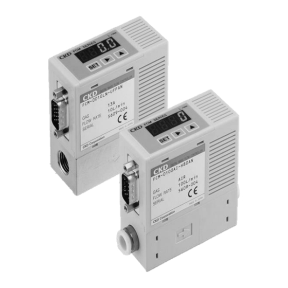
- Page 1 Compact Flow Rate Controller Rapiflow® FCM Series INSTRUCTION MANUAL SM-358642-A/7 SM-358642 • Read this Instruction Manual before using the product. • Read the safety notes carefully. • Keep this Instruction Manual in a safe and convenient place for future reference.
-
Page 2: Preface
• Since there are a wide variety of customer applications, it is impossible for CKD to be aware of all of them. Depending on the application or usage, the product may not be able to exercise its full performance or an accident may occur due to fluid, piping, or other conditions. -
Page 3: Safety Information
SM-358642-A/7 SAFETY INFORMATION SAFETY INFORMATION When designing and manufacturing any device incorporating the product, the manufacturer has an obligation to ensure that the device is safe. To that end, make sure that the safety of the machine mechanism of the device, the pneumatic or water control circuit, and the electric system that controls such mechanism is ensured. -
Page 4: Precautions On Product Use
• For applications where life or properties may be adversely affected and special safety measures are required. (Exception is made if the customer consults with CKD prior to use and understands the specifications of the product. However, even in that case, safety measures must be taken to avoid danger in case of a possible failure.) - Page 5 SM-358642-A/7 SAFETY INFORMATION WARNING Do not use the product as a meter for commercial transactions. The product does not comply with the Measurement Act (of Japan) or equivalent measurement acts of any country and cannot be used for commercial transactions. Use the product within the fluid temperature range of 0°C to 50°C.
-
Page 6: Precautions On Maintenance
SM-358642-A/7 SAFETY INFORMATION WARNING When using a mixture of hydrogen or helium gas and other gases, make sure not to let gases used in each FCM Series controller to flow into other FCM Series controllers. For use in a parallel circuit as shown in the figure below, if hydrogen or helium gas flows into a product not designed for hydrogen or helium gas, the product may not operate due to the safety circuit of the sensor. -
Page 7: Table Of Contents
SM-358642-A/7 CONTENTS CONTENTS PREFACE ........................... i SAFETY INFORMATION ....................ii Precautions on Product Use ..................iii Precautions on Working Fluid ..................iii Precautions on Maintenance ..................v CONTENTS ........................vi PRODUCT OVERVIEW ..................... 1 Model Number Indication ..................1 1.1.1 General gas model .................. -
Page 8: Contents
SM-358642-A/7 CONTENTS 3.3.2 Using the designated range mode .............. 43 Operation Flow ....................44 TROUBLESHOOTING..................... 48 Problems, Causes, and Solutions ..............48 Error Code ......................50 WARRANTY PROVISIONS ..................51 Warranty Conditions ..................51 Warranty Period ....................51 2018-11-12... -
Page 9: Product Overview
SM-358642-A/7 1. PRODUCT OVERVIEW 1. PRODUCT OVERVIEW 1.1 Model Number Indication 1.1.1 General gas model 9500 H6 0 AN 6 ((i) Traceability (h) Bracket Model Symbol Description (a) Flow rate range (a) Flow rate Applicable fluid range ● ● ● ●... -
Page 10: Hydrogen/Helium Model
SM-358642-A/7 1. PRODUCT OVERVIEW 1.1.2 Hydrogen/helium model 8A 0 AN R 1 B T 0002 (i) Traceability Model (h) Bracket Symbol Description (a) Flow rate range (a) Flow rate Applicable fluid range 0002 0 L/min to 2 L/min 0005 0 L/min to 5 L/min 0010 0 L/min to 10 L/min 0020... -
Page 11: Optional Parts
SM-358642-A/7 1. PRODUCT OVERVIEW 1.1.3 Optional parts Dedicated bracket Model number: FCM-LB1 Optional cable (9-conductor cable for analog input type) Model number: FCM-AC1, AC3 Shielded wire Optional cable (15-conductor cable for parallel input type) Model number: FCM-PC1, PC3 Shielded wire 2018-11-12... -
Page 12: Specifications
SM-358642-A/7 1. PRODUCT OVERVIEW 1.2 Specifications 1.2.1 General gas model Model no. FCM-[(a)] [(b)]-[(c)] [(d)] [(e)] Descriptions Valve actuation Proportional solenoid valve: Closed when not energized Full-scale flow rate (Air, nitrogen) (Argon) (Oxygen) (City gas) (Methane) (Propane) 9500 500 mL/min 0001 1 L/min 0002... - Page 13 SM-358642-A/7 1. PRODUCT OVERVIEW Model no. FCM-[(a)] [(b)]-[(c)] [(d)] [(e)] Descriptions 0 VDC to 10 VDC (6.7 kΩ)/4 points (2-bit) Input 0 VDC to 5 VDC (10 kΩ)/4 points (2-bit) signal(input impedance)/ 4 mADC to 20 mADC (250 Ω)/4 points (2-bit) preset Parallel 10-bit/none input...
- Page 14 SM-358642-A/7 1. PRODUCT OVERVIEW Note 7, Note 8 Standard differential pressure type: Pressure specifications Flow rate range (a) 9500 0001 0002 0005 0010 0020 0050 0100 Standard differential pressure (kPa) Operating differential 20 to 150 50 to 200 50 to 250 50 to 250 50 to 250 100 to 300 150 to 300 250 to 350 pressure (kPa)
-
Page 15: Hydrogen/Helium Model
SM-358642-A/7 1. PRODUCT OVERVIEW 1.2.2 Hydrogen/helium model Model no. FCM-[(a)] [(b)]-[(c)] [(d)] [(e)] Descriptions Valve actuation Proportional solenoid valve: Closed when not energized Full-scale flow rate Hydrogen (H2) Helium (HE) 0002 2 L/min 0005 5 L/min Note 1 Flow rate range 0010 10 L/min 0020... - Page 16 SM-358642-A/7 1. PRODUCT OVERVIEW Model no. FCM-[(a)] [(b)]-[(c)] [(d)] [(e)] Descriptions Mounting orientation No restriction Wetted part material Stainless steel, fluoro rubber, alumina, semiconductor silicon, solder 8A/UF Approx. 480 g Weight 4S/4RM Approx. 560 g Degree of protection Equivalent to IP40 (IEC standard) Power reverse connection protection, switch output reverse connection protection, Note 6 Protection circuit...
-
Page 17: Dimensions
SM-358642-A/7 1. PRODUCT OVERVIEW 1.3 Dimensions 1.3.1 Resin body Model number: FCM-□-H8/H6□ Port size: Push-in (ø8) or (ø6) The panel for FCM-□-□R□ is upside-down. 2-#4-40UNC High-density D-sub connector 15-pin/plug (male) ø6 push-in fitting ø8 push-in fitting 2-M3, 5 deep 2018-11-12... -
Page 18: Stainless Steel Body
SM-358642-A/7 1. PRODUCT OVERVIEW 1.3.2 Stainless steel body Model number: FCM-□-8A/UF□ Port size: Rc1/4 or 9/16-18UNF The panel for FCM-□-□R□ is upside-down. 2-#4-40UNC High-density D-sub connector 15-pin/plug (male) Rc1/4 9/16-18UNF 2-M3, 5 deep 9/16-18UNF Mesh filter 9/16-18UNF 11.5 deep (effective thread) 2018-11-12... - Page 19 SM-358642-A/7 1. PRODUCT OVERVIEW Model number: FCM-□-4S Port size: 1/4-inch double bite-type fitting 2-#4-40UNC The panel for FCM-□-□R□ is upside-down. High-density D-sub connector 15-pin/plug (male) Port size: 2-1/4 inch Double bite-type fitting 2-M3, 5 deep 2018-11-12...
- Page 20 SM-358642-A/7 1. PRODUCT OVERVIEW Model number: FCM-□-4RM Port size: 1/4-inch JXR male fitting 2-#4-40UNC The panel for FCM-□-□R□ is upside-down. High-density D-sub connector 15-pin/plug (male) Port size: 2-1/4 inch JXR male fitting 2-M3, 5 deep 2018-11-12...
-
Page 21: Functions
SM-358642-A/7 1. PRODUCT OVERVIEW 1.4 Functions Compatible model Analog input Parallel input Function Description Usage Analog Switch Analog Switch output output output output P.31 Direct Target value can be input with keys. Even without external input signals, control P.32 memory flow rate can be freely adjusted with operation keys. - Page 22 SM-358642-A/7 1. PRODUCT OVERVIEW Compatible model Analog input Parallel input Function Description Usage Analog Switch Analog Switch output output output output Flow rate display is turned off if there are no operations for approximately one Automatic minute. (Control is not stopped by automatic power off.) Power is saved since P.45 power off the display is turned off when not needed.
-
Page 23: Names And Functions Of Display And Operation Panel
SM-358642-A/7 1. PRODUCT OVERVIEW 1.4.1 Names and Functions of Display and Operation Panel 3-digit number LED display (green) Output indicator (red) ● In the RUN mode (instantaneous flow rate screen), the ● “F” is displayed during function setting. instantaneous flow rate and the function setting data ●... -
Page 24: Installation
SM-358642-A/7 2. INSTALLATION 2. INSTALLATION 2.1 Environment WARNING Do not use the product in an atmosphere that contains corrosive gas such as sulfur dioxide gas. Use the product within the ambient temperature range of 0°C to 50°C. Even if the temperature is within the specified range, do not use the product in places where sudden changes in the temperature may cause condensation. - Page 25 SM-358642-A/7 2. INSTALLATION CAUTION Check for leakage currents from the external control devices to prevent a malfunction. Leakage current from equipment such as PLC may cause the product to malfunction. Consult the manufacturer of the output device when driving multiple units of this model with a single output device.
-
Page 26: Mounting
SM-358642-A/7 2. INSTALLATION 2.2 Mounting Mounting directly Secure with the screws. Mounting with dedicated bracket Dedicated bracket model number: FCM-LB1 2018-11-12... -
Page 27: Piping
SM-358642-A/7 2. INSTALLATION 2.3 Piping 2.3.1 Pipe cleaning Before piping, blow air into the pipes to clean and remove cutting chips and foreign matters. The rectifying unit and the platinum sensor may become damaged if cutting chips or foreign matters enter into the pipes. -
Page 28: Tightening
(This position is called the finger-tight position.) Hold the body securely and tighten the female nut a 1/8 turn (when the gasket material is nickel or SUS316) from the finger-tight position. For other gasket materials, contact your nearest CKD sales office or distributor. Bead Gasket... -
Page 29: Wiring
SM-358642-A/7 2. INSTALLATION 2.4 Wiring DANGER Use the product within the specified power supply voltage range. Applying voltage beyond the specified range may cause a malfunction, damage to the product, electric shock, or fire. Do not connect a load exceeding the rated output. The output circuit may become damaged or a fire may occur. - Page 30 SM-358642-A/7 2. INSTALLATION CAUTION Use a cable that is 3 m or shorter. If a cable that is longer than 3 m is used, the errors of analog I/O signals may become larger or the control may become unstable due to wiring resistance. Using a cable that is shorter than 3 m is recommended.
-
Page 31: D-Sub Connector
SM-358642-A/7 2. INSTALLATION 2.4.1 D-sub connector CAUTION Lock the D-sub connector to prevent it from falling off. Check the direction of the connector, insert it all the way in, and lock it so that it does not come off. When loosening the lock, secure the fixing base with a tool. 2018-11-12... -
Page 32: Cable Connection
SM-358642-A/7 2. INSTALLATION 2.4.2 Cable connection Analog input type Model number: FCM-□-□0/1/2□ D-sub 6 to socket pin no. Optional cable Brown Orange Yellow Gray White Green Blue Black insulator color Preset input Analog Switch Error Item Power Input signal signal output output... -
Page 33: Example Of Internal Circuit And Load Connection
SM-358642-A/7 2. INSTALLATION 2.4.3 Example of internal circuit and load connection Input Type: Analog, Output Type: Analog + error (NPN) Model number: FCM-□-□0/1/2AN□ Pin 5 (power +) Pin 11 (analog input) Signal generator Pin 1 (preset bit 1) Pin 2 (preset bit 2) Pin 3 (integration reset) - Page 34 SM-358642-A/7 2. INSTALLATION Input Type: Analog, Output Type: Analog + error (PNP) Model number: FCM-□-□0/1/2AP□ Pin 5 (power +) Pin 13 (analog output) Output short-circuit Max. 50 mA Pin 14 protection circuit (error output) Pin 11 (analog input) Signal generator Pin 1 (preset bit 1) Load...
- Page 35 SM-358642-A/7 2. INSTALLATION Input Type: Parallel, Output Type: Analog + error (NPN) Model number: FCM-□-□PAN□ Pin 5 (power +) Pin 12 (MSB bit 10) Pin 11 (bit 9) Pin 9 (bit 8) Pin 8 (bit 7) Pin 7 (bit 6) Pin 6 (bit 5) Pin 4 (bit 4) Pin 3 (bit 3)
- Page 36 SM-358642-A/7 2. INSTALLATION Input Type: Parallel, Output Type: Analog + error (PNP) Model number: FCM-□-□PAP□ Pin 5 (power +) Pin 13 (analog output) Max. 50 mA Pin 14 (error output) Pin 12 (MSB bit 10) Pin 11 (bit 9) Pin 9 (bit 8) Pin 8 (bit 7) Pin 7 (bit 6)
-
Page 37: Usage
SM-358642-A/7 3. USAGE 3. USAGE WARNING Warm up the product (at least 10 minutes) before use. Output accuracy is affected not only by the temperature characteristics but also by the heat generated from energization. Stop the device before changing the settings of the product. The control system devices may operate unintentionally. - Page 38 SM-358642-A/7 3. USAGE CAUTION Use the product in places where it is not subject to impacts from falling objects and vibrations since a micro sensor chip is incorporated. Handle the product as a precision component during installation and transportation. If an abnormality occurs during operation, immediately stop using the product, turn off the power and contact your dealer.
-
Page 39: Flow Rate Control
SM-358642-A/7 3. USAGE 3.1 Flow Rate Control 3.1.1 Controlling the flow rate with the direct memory function The target value can be input with the keys. Even without external input signals, the control flow rate can be freely adjusted with the operation keys. The direct memory function has two action modes. Direct memory (1): Settings are applied when the value is changed (the flow rate can be changed without confirming the value). - Page 40 SM-358642-A/7 3. USAGE Operating the direct memory (2) Turn on the power. <Instantaneous flow rate display> The instantaneous flow rate is displayed. Approx. 3 seconds later, the screen returns to the Press the key. instantaneous flow rate display. The F1: Input signal confirmation screen is displayed and the present input signal type and <F1: Input signal confirmation>...
-
Page 41: Controlling The Flow Rate With The Preset Input Function (Analog Input Type Only)
SM-358642-A/7 3. USAGE 3.1.2 Controlling the flow rate with the preset input function (analog input type only) The flow rate can be switched by setting four flow rates and inputting a 2-bit signal from an external source. Example: To control 0, 1, 2, and 5 L/min with D-sub socket pin no. -
Page 42: Changing The Settings With The Shortcut Keys (Only When Using The Direct Memory Or Preset Input Functions)
SM-358642-A/7 3. USAGE 3.1.3 Changing the settings with the shortcut keys (only when using the direct memory or preset input functions) When controlling the flow rate with the direct memory or the preset input, the setting change screen can be displayed with a single key operation using a shortcut key. •... -
Page 43: Controlling The Flow Rate With The Analog Input Function (Analog Input Type Only)
SM-358642-A/7 3. USAGE 3.1.4 Controlling the flow rate with the analog input function (analog input type only) The flow rate can be controlled with analog input signals. Controlling with analog input signals <Instantaneous flow rate display> Turn on the power. The instantaneous flow rate is displayed. -
Page 44: Controlling The Flow Rate With The Parallel Input Function (Parallel Input Type Only)
SM-358642-A/7 3. USAGE 3.1.5 Controlling the flow rate with the parallel input function (parallel input type only) The flow rate can be controlled with a parallel 10-bit signal (signal from PLC or other controllers). An expensive I/O device, such as a D/A converter, is not required. The parallel input signal is 10-bit and ranges from 0 to 1023 when converted to a decimal number. - Page 45 SM-358642-A/7 3. USAGE Controlling with parallel input signals <Instantaneous flow rate display> Turn on the power. Approx. 3 seconds later, the screen The instantaneous flow rate is displayed. returns to the instantaneous flow rate display. Press the key. <F1: Input signal confirmation> <Input value display>...
-
Page 46: Flow Rate Integration
SM-358642-A/7 3. USAGE 3.2 Flow Rate Integration 3.2.1 Displaying the integrated flow rate The integrated flow rate can be displayed. The display range is as shown in the following table. 9500 0001 0002 0005 0010 Model: FCM- 0020 0050 0100 L9500 L0001 L0002... -
Page 47: Closing The Proportional Solenoid Valve At The Set Integrated Flow Rate
SM-358642-A/7 3. USAGE 3.2.2 Closing the proportional solenoid valve at the set integrated flow rate The proportional solenoid valve is closed when the flow rate reaches the set integrated flow rate. This is suitable for a process where filling with a certain amount of flow rate is necessary. ... -
Page 48: Outputting The Integrated Pulse (Switch Output Type Only)
SM-358642-A/7 3. USAGE 3.2.3 Outputting the integrated pulse (switch output type only) The integrated pulse is output. For the pulse rate, refer to "1.2 Specifications". For the switch output cable connection, refer to "2.4.2 Cable connection" and "2.4.3 Example of internal circuit and load connection". -
Page 49: Turning The Switch On With The Set Integrated Flow Rate (Switch Output Type Only)
SM-358642-A/7 3. USAGE 3.2.4 Turning the switch ON with the set integrated flow rate (switch output type only) The switch output is turned ON at the set integrated flow rate. For the switch output cable connection, refer to "2.4.2 Cable connection" and "2.4.3 Example of internal circuit and load connection". -
Page 50: Switch Output (Switch Output Type Only)
SM-358642-A/7 3. USAGE 3.3 Switch Output (Switch Output Type Only) 3.3.1 Using the tolerance mode H (+ tolerance) The switch output turns ON when the actual flow rate Input signal set value is within the tolerance of the input signal set value. L (−... -
Page 51: Using The Designated Range Mode
SM-358642-A/7 3. USAGE 3.3.2 Using the designated range mode H (higher limit) The switch output turns ON when the actual flow rate is outside the specified range. Higher and lower limit values are set regardless of the input signal set value L (lower limit) (control target value). -
Page 52: Operation Flow
SM-358642-A/7 3. USAGE 3.4 Operation Flow <Normal display> <Key lock> <Instantaneous flow rate display> Flow rate controlled state Approx. 2 seconds later, the screen returns to the instantaneous flow rate 2 seconds display. The present instantaneous flow rate is displayed. <Key lock release>... - Page 53 SM-358642-A/7 3. USAGE <F1: Input signal selection> Approx. 3 seconds later Select input type for control. <Instantaneous flow rate display> is Direct memory (1): Settings are applied when the value is changed. displayed. <F1 screen> <Direct memory input setting> After confirmation, the setting mode returns to <F1 screen>.
- Page 54 SM-358642-A/7 3. USAGE Approx. 3 seconds later <Instantaneous flow rate display> <F2: Input signal zero/span adjustment> is displayed. <F2 screen> If using at full-scale <Setting the target value> After confirmation, the setting key: Moves the digit. mode returns to <F2 screen>. key: Increases the value.
- Page 55 SM-358642-A/7 3. USAGE Approx. 3 seconds later <Instantaneous flow rate <F5: Integrated flow rate automatic shut-off setting> display> is displayed. If not using the integrated flow rate automatic shut-off <F5 screen> After confirmation, the setting mode returns to <F5 screen>. 2 seconds 2 seconds If using the integrated flow rate automatic shut-off...
-
Page 56: Troubleshooting
SM-358642-A/7 4. TROUBLESHOOTING 4. TROUBLESHOOTING 4.1 Problems, Causes, and Solutions If the product does not operate as intended, check the table below for a possible solution. Problem Cause Solution Release the key lock according to "3.4 Operation Setting cannot be Key is locked. - Page 57 Note 2: The analog output type does not have a switch output function. Note 3: The operation pattern differs in the tolerance mode and the designated range mode. If you have any other questions or concerns, contact your nearest CKD sales office or distributor. 2018-11-12...
-
Page 58: Error Code
● Check the product input signal type and adjust the (Detected at input of 110%FS or more. input signal so that it is within the rated range. Detection accuracy is ± 1%FS.) ● Contact your nearest CKD sales office or Error occurred during EEPROM reading or writing. distributor. -
Page 59: Warranty Provisions
If the product specified herein fails for reasons attributable to CKD within the warranty period specified below, CKD will promptly provide a replacement for the faulty product or a part thereof or repair the faulty product at one of CKD’s facilities free of charge.
Need help?
Do you have a question about the Rapiflow FCM Series and is the answer not in the manual?
Questions and answers