Table of Contents
Advertisement
Quick Links
AX1R Series
AX2R Series
AX4R Series
Direct Drive Actuator
INSTRUCTION MANUAL
Before operating the product, read this instruction manual without fail.
Among all, carefully read the description related to safety.
Keep this instruction manual in a safe place so that it can be referred to whenever necessary.
2023-09-14
SM-A83981-A
Advertisement
Table of Contents

Subscribe to Our Youtube Channel
Related Manuals for CKD AX1R Series


Summary of Contents for CKD AX1R Series
- Page 1 AX1R Series AX2R Series AX4R Series Direct Drive Actuator INSTRUCTION MANUAL Before operating the product, read this instruction manual without fail. Among all, carefully read the description related to safety. Keep this instruction manual in a safe place so that it can be referred to whenever necessary.
-
Page 2: Introduction
INTRODUCTION Thank you for selecting our ABSODEX. ABSODEX is a direct drive indexing unit developed to drive intermittently operated turntables or the like of general industrial assembling machines and testing machines flexibly and accurately. This instruction manual is exclusively for ABSODEX AX1R, AX2R, and AX4R series. It is inapplicable to other types. -
Page 3: For Safety Operation
FOR SAFETY OPERATION When designing and manufacturing equipment using this product, it is your duty to manufacture safe equipment. To do this, make sure that the safety of the mechanical mechanism of the equipment and the system that controls it electrically can be ensured. - Page 4 < WARNING Symbols > Indicates a generic mark that Indicates a mark that prohibits shows prohibited (must-not-do) the act of touching the device. activities. Indicates a generic mark that Indicates a mark that prohibits warns the risk of electric shock the act of putting fingers inside.
-
Page 5: Precautions For Using The Product
Precautions for Using the Product DANGER Do not attach or remove connectors with the power on. A malfunction, failure or electric shock may be caused. Do not operate in explosive or fire atmosphere. Do not use this product for the following purposes. ... - Page 6 WARNING Handling should be done by persons with sufficient knowledge and experience. This product is designed and manufactured as equipment and part for general industrial machinery. Use within the specifications of the product. This product cannot be used outside of the product-specific specifications. ...
-
Page 7: Table Of Contents
CONTENTS INTRODUCTION ....................2 FOR SAFETY OPERATION .................. 3 Precautions for Using the Product ................... 5 CONTENTS ......................7 1. PRODUCT OVERVIEW ................. 9 System Configuration ..................... 9 Instruction Manual for the Product ..............11 Name of Each Part ....................12 Model Number Indication .................. - Page 8 8. TERMS OF WARRANTY ................42 9. REFERENCE INFORMATION ..............43 Specification ......................43 2023-09-14 SM-A83981-A...
-
Page 9: Product Overview
PRODUCT OVERVIEW System Configuration When in use, the AX1R, AX2R, and AX4R series must be connected to the AXD series driver. System Configuration Example < System Configuration > ABSODEX Actuator unit (Encoder Cable) Note 1 (Power Cable) Driver unit USB cable (mini-B) Molded case Noise filter circuit breaker... - Page 10 When using a circuit breaker, select one that has high frequency countermeasures for inverter use. List of Peripheral Devices Product name and model Component Manufacturer number AX1R Series This product Actuator AX2R Series AX4R Series Driver AXD Series CKD Corporation...
-
Page 11: Instruction Manual For The Product
Instruction Manual for the Product This instruction manual is the "SM-A83981." The instruction manual for this product is as follows. Driver Actuator SM-A83981 SM-A61663 AX1R Series AXD Series AX2R Series Parallel I/O Specification AX4R Series SM-A63468 AXD Series CC-Link Specification... -
Page 12: Name Of Each Part
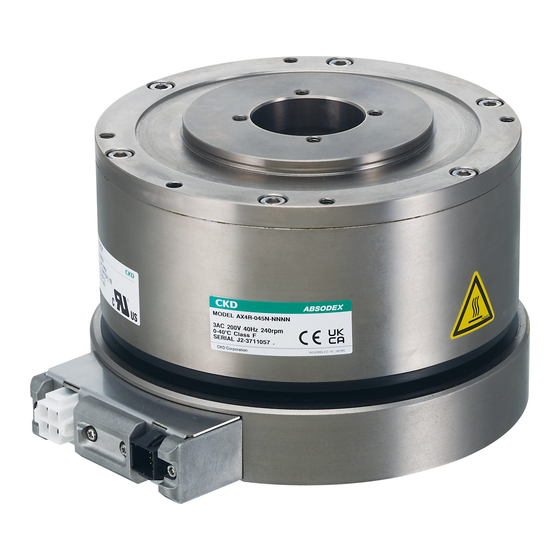
Name of Each Part AX1R Hollow hole Output axis Moving part (rotating part) Encoder cable connector Power cable connector AX2R Hollow hole Output axis Moving part (rotating part) Encoder cable connector Power cable connector AX4R Hollow hole Output axis Moving part (rotating part) Power cable connector Encoder cable connector... -
Page 13: Model Number Indication
Model Number Indication AX1R Series AX1R- Size (maximum Connector installation Installation base output torque) direction Standard (without 22N・m Standard (connector installation base) side installation) 45N・m With installation base Connector lower 75N・m installation 150N・m 210N・m AX2R Series AX2R- Size (maximum Installation base... - Page 14 AX4R Series AX4R- Size (maximum Installation base Brake output torque) Standard (without Standard (without 9N・m installation base) electromagnetic brake) 22N・m With installation base With negative-actuated electromagnetic brake 45N・m 75N・m 150N・m 300N・m 500N・m 1000N・m 2023-09-14 SM-A83981-A...
-
Page 15: Installation
INSTALLATION DANGER Do not use in areas where dangerous materials such as igniters, flammables and explosives are present. This may cause ignition, flames, or explosions. Do not work with wet hands. This may cause electric shock. Do not attach or remove connectors with the power on. ... - Page 16 WARNING Safety circuits or safety devices shall be designed to prevent equipment damage or personal injury in the event that the machine stops due to a system malfunction, such as an emergency stop or power failure. Waterproof the actuator when used in an environment with water or oil.
- Page 17 CAUTION Do not perform the withstand voltage test or the insulation resistance test on the equipment to which this product is installed. In this circuit design, the product may be damaged if the withstand voltage test and the insulation resistance test are performed on the equipment to which the product is installed.
- Page 18 Otherwise, maintenance and inspection cannot be performed, resulting in equipment stoppage, damage, and injury. Customers are responsible for confirming the compatibility of the CKD product with their system, machine, and device. When transporting or installing the product, ensure the safety of workers by supporting the product securely with lifts and supports and by using more than one worker.
-
Page 19: Installation Environment
Installation Environment Check the ambient temperature and atmosphere of the product specifications before storing or using the product. Use in a place where the ambient temperature is 0 to 40 °C. Ventilate if heat builds Use in a place where the ambient humidity is 20 to 85% RH. Use in a non- condensing environment. -
Page 20: Installation Method
Installation Method Precautions for Installation The machine for which ABSODEX is installed should have the maximum rigidity, so that ABSODEX will perform as designed. This rigidity requirement bases on that relatively low number of mechanical natural frequency (approximately 200 to 300Hz) of a load machine, and deck will cause ABSODEX to resonate with the machine and its deck. - Page 21 When ABSODEX cannot be directly mounted on a machine, it should be mounted on the deck having as much rigidity as possible. Example: Mounting with the shafts × 〇 2023-09-14 SM-A83981-A...
- Page 22 Anti-vibration Using Dummy Inertia Plate When sufficient rigidity is not available for a machine, a dummy inertia plate at the nearest position to the actuator will help reduce resonance with the machine. The following explains the installation of a dummy inertia plate. Guideline for the magnitude of a dummy inertia is: Load inertia x (0.2 to 1).
- Page 23 Connections by belts, a gear, a spline, and a key will cause machine rigidity to be reduced. In such instance, dummy inertia should be assumed to be load inertia x (0.5 to 2). When speed is reduced using belts or gear, load inertia should be the value converted by the actuator output axis, and dummy inertia plate should be installed at the actuator side.
- Page 24 Installation Direction The actuator can be installed horizontally (on the floor or on the ceiling) or vertically. 〇 〇 WARNING If the servo is turned off (including safety function, forced stop, and alarm) while rotational force is applied by gravity or other force action, the rotational force may cause the actuator to rotate.
-
Page 25: Usage
USAGE DANGER Do not enter the operating area while the actuator is ready for operation. There is a risk of injury. Do not work with wet hands. This may cause electric shock. WARNING Do not rotate the actuator output axis at 30 rpm or more with the power off. - Page 26 CAUTION Do not frequently turn the power on and off. Doing so may damage the internal elements of the controller. Do not operate the output axis for several seconds after power-on. An alarm may occur. When changing the combination of the actuator and the controller, be sure to check the program and parameters before operating.
-
Page 27: Maintenance Inspection
MAINTENANCE INSPECTION DANGER TURN OFF POWER when making maintenance inspection or changing switches in the driver with the side cover removed as electrical shock due to high voltage can occur. There is a risk of injury. Do not work with wet hands. ... -
Page 28: Periodical Inspection
Re-tighten screws and Loose screws and connectors. Inspect for looseness. connectors. Abnormal noise from actuator. Confirm by hearing. Request CKD to repair. Cuts and crack in cable. Inspect visually. Replace faulty cable. Check the power supply system Confirm the supply... -
Page 29: Precautions For Product Disposal
Precautions for Product Disposal CAUTION The product is disposed by a specialized waste-disposal company in accordance with the "Waste Disposal and Public Cleansing Law." 2023-09-14 SM-A83981-A... -
Page 30: Troubleshooting
TROUBLESHOOTING < Troubleshooting (1/4) > Symptom Probable Cause Countermeasures Voltage is not measured (confirmed Check the power system. by a tester). Power does not turn on. Fuse inside the driver is blown. Replace or repair the driver. ... - Page 31 < Troubleshooting (2/4) > Symptom Probable Cause Countermeasures The actuator is loosely tightened. Tighten bolts. Be sure to carry out. Load is excessive. Reduce speed. Connection of the drive to actuator Cable connection check is not right.
- Page 32 < Troubleshooting (3/4) > Symptom Probable Cause Countermeasures Power voltage is low. Check the power system. Instantaneous power failure has Check the power system. occurred. Alarm 6 lights. Power resumed immediately after Turn off power, and turn it on power off.
- Page 33 < Troubleshooting (4/4) > Symptom Probable Cause Countermeasures The program area is full. Delete unnecessary programs. Program data is broken. Clear the program memory area and enter again. (L17_9999) Write protection state Check the start input wait output.
-
Page 34: Support For Ul Standard
UL-compliant product. Operation of this equipment requires detailed installation and operation instructions provided in the instruction manual intended for use with this product. Manufacturer’s name: CKD Corporation Applicable Standards Item UL Standard... - Page 35 Precautions SOAC (Safe Operating Area of Continuous operation) curve The load condition being used must be within the SOAC curve. AX1R Series 2023-09-14 SM-A83981-A...
- Page 36 AX2R Series 2023-09-14 SM-A83981-A...
- Page 37 AX4R Series 2023-09-14 SM-A83981-A...
- Page 38 Specification AX1R Series Item AX1R-022 AX1R-045 AX1R-075 AX1R-150 AX1R-210 1. Continuous Output Torque (N·m) 2. Maximum Output Torque (N·m) 3. Rated Speed (rpm) 240(S7) 240(S7) 140(S7) 120(S7) 120(S7) 4. Rated Input Voltage 5. Rated Input Current 6. Inertia of motor (kg·m...
- Page 39 AX4R Series Item AX4R-009 AX4R-022 AX4R-045 AX4R-075 1. Continuous Output Torque (N·m) 2. Maximum Output Torque (N·m) 3. Rated Speed (rpm) 240(S7) 240(S7) 240(S7) 127(S7) 4. Rated Input Voltage 5. Rated Input Current 6. Inertia of motor (kg·m 0.009 0.0206 0.0268 0.1490 7.
-
Page 40: Support For European Standards
SUPPORT FOR EUROPEAN STANDARDS If this product is used as EN-compliant application, be sure to read this section before use. A product on which a CE and a UKCA marks are attached is compliant with European Standards. A product on which no marks are attached is not compliant with European Standards. - Page 41 Operating Environment Condition Temperature Humidity Atmospheric Pressure 20 to 85%RH, no During operation 0 to 40°C 86 kPa to 106 kPa condensation 20 to 90%RH, no During storage -20 to 80°C 86 kPa to 106 kPa condensation During 20 to 90%RH, no -20 to 80°C 86 kPa to 106 kPa transportation...
- Page 42 Scope In the event of a failure that is clearly CKD's responsibility during the warranty period described above, we will provide a replacement for this product or any necessary replacement parts free of charge, or repair at CKD Plant free of charge.
- Page 43 REFERENCE INFORMATION Specification Item AX1R-022 A X 1 R - 0 4 5 AX1R-075 AX1R-150 AX1R-210 Maximum Output Torque N・m Continuous Output Torque N・m Maximum Rotation Speed Note 1 Note 1 Note 1 Allowable Axial Load 2200 Allowable Moment Load N・m Output Axis Inertia Moment 0.00505 0.00790...
- Page 44 Item AX2R-006 AX2R-012 AX2R-018 Maximum Output Torque N・m 12.0 18.0 Continuous Output TorqueN・m Maximum Rotation Speed Note 1 Allowable Axial Load 1000 Allowable Moment Load N・m Output Axis Inertia Moment 0.00575 0.00695 0.00910 kg・m Allowable Load Inertia Moment kg・m Indexing Accuracy ±30 Repeating Accuracy ±5...
- Page 45 Item AX4R-009 AX4R-022 AX4R-045 AX4R-075 Maximum Output Torque N・m Continuous Output Torque N・m Maximum Rotation Speed Note 1 Allowable Axial Load 3700 3700 20000 Allowable Moment Load N・m Output Axis Inertia Moment 0.0090 0.0206 0.0268 0.1490 kg・m Allowable Load Inertia Moment 1.75 3.00 5.00...
- Page 46 Item AX4R-150 AX4R-300 AX4R-500 AX4R-10W Maximum Output Torque N・m 1000 Continuous Output Torque N・m Maximum Rotation Speed Allowable Axial Load 20000 Allowable Moment Load N・m Output Axis Inertia Moment 0.2120 0.3260 0.7210 2.7200 kg・m Allowable Load Inertia Moment 75.00 180.00 300.00 600.00 kg・m...
Need help?
Do you have a question about the AX1R Series and is the answer not in the manual?
Questions and answers