Table of Contents
Advertisement
Quick Links
Advertisement
Table of Contents

Related Manuals for CKD FCM Series


Summary of Contents for CKD FCM Series
- Page 1 COMPACT FLOW RATE CONTROLLER FCM SERIES CC-793A...
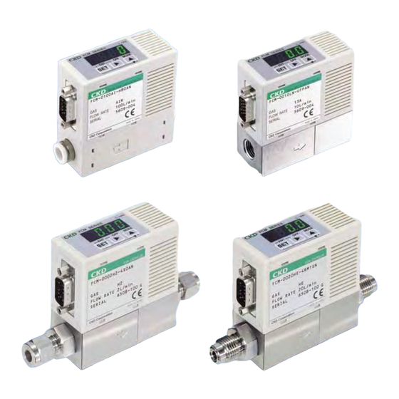
- Page 2 0.015 to 10 ℓ/min 0.06 to 20 ℓ/min Weight: approx. 480 g Resin body Rectification structure with Applicable fluid and flow rate improved low pressure loss and reproducibility 0.015 to 100 ℓ/min Weight: approx. 200 g Compact flow rate controller FCM Series...
-
Page 3: Rohs Compliant
High performance and economic efficiency for all of sensor function, proportional control function, valve function, to satisfy various purposes Compact flow rate controller FCM Series. Mounted digital display, which allows Compatible with different fluids us to see control status at a glance Applicable fluid: various gas including air, nitrogen, argon, oxygen, methane, propane. -
Page 4: Examples Of Applications
Examples of applications Useful in different fields This compact flow rate controller is used for different applications including machinery, automobile, and precision device fields, advanced fields such as semiconductors and biotechnology, medicine and food. Flow rate (ℓ/min) Semiconductor Wire bonding Appropriate for wire bonding tension control requiring high accuracy. -
Page 5: Input/Output Specifications
Pre-set: 4 points (2bit) (Note) Switch FCM-*-*2SP FCM-*-*PAN Analog 1 to 5 V FCM-*-*PAP Parallel: 10bit FCM-*-*PSN Switch FCM-*-*PSP Note: Preset 8-point (3-bit) input is used customized. The external integration reset signal input cannot be used. Contact your CKD Sales Office for details. - Page 6 For air, nitrogen, argon, oxygen, city gas, methane, propane (flow rate range: 0.5 to 100ℓ/min) For hydrogen, helium (flow rate range: 0 to 20ℓ/min) For air, nitrogen, argon, oxygen, city gas, methane, propane FCM series Spe c i f ic a ti on s...
-
Page 7: Specifications
<Recommended circuit> Oil mist filter Filter (micro alescer) Pneumatics Air dryer Regulator FCM Series pressure source <Recommended components> Air filter: F series Oil mist filter: M series Note 3: City gas 13A is a value for methane (CH ) 88% gas. - Page 8 Series Hydrogen and helium FCM Series Spe c i f ic a ti on s Descriptions FCM-[*1][*2]-[*3][*4][*5] Valve drive type Proportional solenoid valve When not energized: Closed Flow rate range H2 (Hydrogen) HE (helium) 0002 0 to 2 ℓ/min Full scale flow 0005 0 to 5 ℓ/min...
- Page 9 Series Specifications Pressure Standard differential pressure and operation differential pressure Flow rate range *1 0002 0005 0010 0020 Standard differential pressure (kPa) Operation differential 10 to 50 30 to 80 30 to 80 30 to 80 pressure (kPa) Standard differential pressure (kPa) Operation differential 20 to 100...
- Page 10 Analog 0 to 10 VDC <Example of model No.> Analog 0 to 5 VDC FCM-0001AI-H81ANR1BK Analog 4 to 20 mADC Parallel 10bit Model: Small size flow rate controller FCM series Flow rate range : 0 to 1 ℓ/min Output specifications Output specifications Applicable fluid...
- Page 11 Series How to order Hydrogen and helium H o w t o o r de r 0002 Model no. Traceability Bracket Symbol Descriptions Flow rate range Flow rate range Applicable fluid 0002 0 to 2 ℓ/min 0005 0 to 5 ℓ/min 0010 0 to 10 ℓ/min 0020...
- Page 12 Series Dimensions Body material: Resin, port size: ø6, ø8 The display direction is reverse for the FCM-*-*R*. FCM-*-H8/H6* 2-# 4-40UNC D sub-connector 15 pin/plug Port size ø6 push-in joint or ø8 push-in joint 2-M3 depth 5 Body material: Stainless steel, port size: Rc1/4, 9/16-18UNF The display direction is reverse for the FCM-*-*R*.
- Page 13 Series Dimensions Dimensions Port size: 1/4" double barbed joint FCM-*-4S The display direction is reverse for the FCM-*-*R*. 2-#4-40UNC D sub-connector 15 pin/plug Port size 1/4" double (121.4) barbed joint 2-M3 depth 5 Port size: 1/4" JXR male joint FCM-*-4RM The display direction is reverse for the FCM-*-*R*.
- Page 14 Series Dedicated bracket (Floor installation type) FCM-LB1 Discrete model: Weight: 28g Cable option dimension drawing 9-conductor cable for analog input type FCM-AC1, AC3 Discrete option model: 28.5 Shield cable * Connect the shield cable to the power supply voltage- (0 V). Cable Weight g 9-AWG26...
-
Page 15: Wiring Method
Series Technical data Wiring method Example of internal circuit and load connection, parallel input type Caution Care must be taken for mis-connection. FCM-*-*0/1/2 AN* FCM-*-*0/1/2 AP* (Analog input, analog output + error output type NPN output) (Analog input, analog output + error output type PNP output) 5 pin (power supply voltage+) 5 pin (power supply voltage+) 11 pin (analog input) - Page 16 Series Example of internal circuit and load connection, parallel input type Caution Care must be taken for mis-connection. FCM-*-*PAN* FCM-*-*PAP* (Parallel input, analog output + error output type NPN output) (Parallel input, analog output + error output type PNP output) 5 pin (power supply voltage+) 5 pin (power supply voltage+) 12 pin (MSB bit 10)
-
Page 17: Functional Explanation
Series Technical data Compact flow rate controller Functions of FCM Series Functional explanation Compatible models Function Descriptions Analog input Parallel input Operation Analog output Switch output Analog output Switch output P14, 15 Direct memory Key input is available for target value. Even if input signals from an external source function are not used, control flow rate is freely adjusted with controller operation keys. -
Page 18: Error Code List
ON again. Output abnormalities are occurred for sensor. (Note 2) If this error occurs again, contact your nearest CKD Sales Office or dealer. Over current protection circuit is actuating for switch Check whether load current exceeds the rating, correctly output. -
Page 19: How To Operate
Series How to operate Controlling the flow rate (1) Controlling the flow rate with direct memory The target is input with keys. Even if input signals from an external source are not used, control flow rate is freely adjusted with controller operation keys. Direct memory has two operation modes. - Page 20 Series Controlling the flow rate <Direct memory (2) operation> (1) Turn power ON. The instantaneous flow rate is displayed. <Instantaneous flow rate display > The instantaneous flow rate display is redisplayed after 3 s. When the key is pressed, the <F1: Input signal confirmation> screen is displayed.
- Page 21 Series How to operate Controlling the flow rate (2) Controlling the flow rate with preset input (only analog input) When four random flow rate points are set, the flow rate is controlled by inputting a 2-bit signal from an external source. Example: To control 0, 1, 2, and 5ℓ/min with preset input, D-sub socket pin No.
- Page 22 Series Controlling the flow rate (3) Changing settings with shortcut keys (only when using direct memory and preset input) When controlling the flow rate using direct memory or preset input, the setting change screen is opened with a single key operation. Note: The input signal setting change screen opens the instant that the shortcut key is pressed.
- Page 23 Series How to operate Controlling the flow rate (4) Controlling the flow rate with analog input (Only analog input) The flow rate is controlled with analog input signals. <Controlling with analog input signals> <Instantaneous flow rate display > (1) Turn power ON. The instantaneous flow rate is displayed. The instantaneous flow rate display is redisplayed after 3 s.
- Page 24 Series Controlling the flow rate (5) Controlling the flow rate with parallel input (Only parallel input) The flow rate is controlled with a parallel 10-bit (signal from PLC, etc.) Expensive input/output devices, such as a D/A converter, are not required. The parallel input signal is a 10-point signal so when converted to a decimal, it becomes 0-1023.
- Page 25 Series How to operate Integrating the flow rate (1) Displaying the integrated flow rate The flow rate is integrated and displayed. The display range is shown below. Integrated flow rate is a calculated (reference) value. 9500 0001 0002 0005 0010 Model No.
- Page 26 Series Integrating the flow rate (3) Outputting the integrated pulse (Only switch output) The integrated pulse is output. Refer to the table on page 20 for the pulse rate. Refer to the connection (page 9), examples of internal circuit and load connection (pages 10 and 11) for details on connecting switch output. <Operation >...
- Page 27 Series How to operate Using switch output (Only switch output) (1) Using the tolerance mode Switch output turns ON when the level is within the tolerance of H (+ tolerance) the input signal setting. Input signal setting The tolerance is set for both the plus side and minus side as a L (- tolerance) %FS (full-scale) See the connection (page 9), examples of internal circuit and load...
- Page 28 Series Using switch output (Only switch output) (2) Using the range designation mode The switch turns ON when the level is not within the designated flow H (upper limit side) rate range. The upper and lower limit values are set regardless of the input signal setting (control target).
-
Page 29: Operation (List)
Series How to operate Operation (List) Note: • Keys are unlocked when the controller is shipped. Lock keys if necessary. The key lock/unlock state is held even if power is turned OFF. • Control does not stop during the F1: input signal selection or F2: input signal zero/span setting. Take safety into consideration and stop control (forced stop) if necessary. - Page 30 Series Operation (List) <F1: input signal selection > Select which input style to use for control. After 3 seconds <Instantaneous Direct memory (1): The setting is applied when the value is changed. flow rate display> <F1 screen > <Direct memory input setting> After setting, the setting mode is exited, and the <F1 screen>...
- Page 31 Series How to operate Operation (List) After 3 s <Instantaneous flow <F2: input signal zero span adjustment > rate display> When using with full-scale <F2 screen > <Target setting> After setting, the key : Moves the digit setting mode is exited, and the <F2 screen>...
- Page 32 Series Operation (List) After 3 s <F5: Integrated automatic shutoff setting screen> <Instantaneous flow rate display> When not using integrated flow rate automatic shutoff <F5 screen > After setting, the setting mode is exited, and the <F5 screen> is displayed. Hold down for 2 s.
-
Page 33: Safety Precautions
Scope of warranty In case any defect attributable to CKD is found during the term of warranty, CKD shall, at its own discretion repair the defect or replace the relevant product in whole or in part, according to its judgement. -
Page 34: Design & Selection
Flow rate controller Safety precautions Always read this section before starting use. Individual precautions: compact flow rate controller FCM Series Design & Selection Pay attention not to let foreign particles into the 1. Applicable fluid product. If foreign matter gets into this product (dirt, water,... - Page 35 Series Individual precautions Design & Selection Due to wiring, the current input power ground and 2. Working environment signal common are the same. When driving several of these products with one WARNING PLC and D/A unit, depending on the D/A unit's Corrosive environment circuit, the correct signal may not be input because Do not use this product in an environment...
-
Page 36: Installation And Adjustment
Provide separate measures for surge signals due to wiring resistance, or unstable applied to the power cable. control. CKD recommend to use cable shorter than... - Page 37 Series Individual precautions Installation & Adjustment When connecting pipes, wrap sealing tape in the 2. Piping opposite direction from threads starting 2mm inside from the end of piping threads. CAUTION If sealing tape protrudes from pipe thread part, it could be Check that the fluid direction and the direction cut when screwed in.
- Page 38 A degree of precision may change from the initial period, due to the using environment or condition. Do not disassemble or modify this product. Doing CKD recommends to check actuation in regular so could result in faults. basis. The case is made of resin. Do not use solvent,...
-
Page 39: Related Products
Apply for compact flow rate controller FCM. Terms Explanation Precision scope of guarantee Calibration range of this product. Calibration difference from CKD basic device. (Condition: temperature 25±3°C, power supply voltage 24 VDC Accuracy ±0.01 V, standard differential pressure, secondary side atmospheric release) Reproducibility Calculate from differences (D = max - min), at the time when 0%F.S. - Page 40 If the goods and their replicas, or the technology and software in this catalog are to be exported, laws require the exporter to make sure they will never be used for the development or the manufacture of weapons for mass destruction. ● Specifications are subject to change without notice. CKD Corporation 2014 All copy rights reserved. 2014.11...
Need help?
Do you have a question about the FCM Series and is the answer not in the manual?
Questions and answers