Table of Contents
Advertisement
Quick Links
Advertisement
Table of Contents

Related Manuals for DGC DC-5000


Summary of Contents for DGC DC-5000
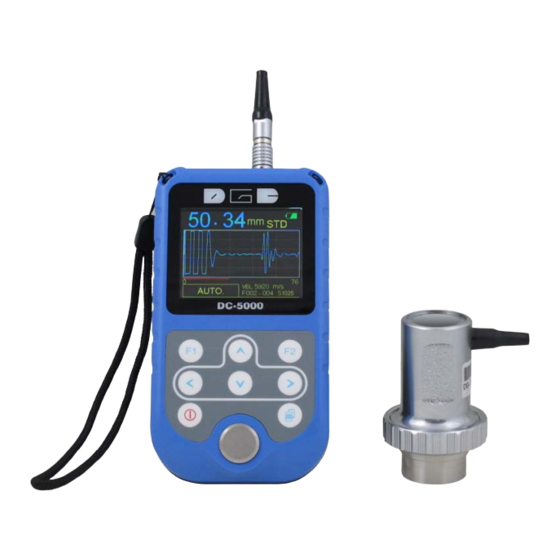
- Page 1 UT Thickness Gauge DC‐5000 Instruction Manual ...
-
Page 2: Table Of Contents
CONTENTS 1. GENERAL DESCRIPTION ................ ‐ 1 ‐ 2. STANDARD DELIVERY .................. ‐ 1 ‐ 3. TECHNICAL SPECIFICATIONS ................ ‐ 2 ‐ 4. OVERVIEW .................... ‐ 2 ‐ 5. KEYPAD FUNCTIONS .................. ‐ 3 ‐ 6. DISPLAY SCREEN .................. ‐ 5 ‐ 7. QUICK STARTUP GUIDE ................ ‐ 8 ‐ 8. MENU ....................... ‐ 10 ‐ ‐ MEA. ) .................. ‐ EASUREMENT 8.1.1 T‐E Mode: ..................... ‐ 10 ‐ Standard Measurement: .................. ‐ 11 ‐ Minimum Measurement: ................. ‐ 11 ‐ ... -
Page 3: General Description
1. General Description DC‐5000 is a visual A / B scan ultrasonic thickness gauge with high energy. It is a Multi‐Mode thickness gauge that has the ability to measure very thick composite material or material that is very hard for ultrasonic to go through. This unit can measure the thickness of metallic and non‐metallic materials such as steel, aluminum, titanium, plastics, ceramics, glass and any other good ultrasonic wave conductor. DC‐5000 comes with following features: ● Large color TFT display ● Automatic probe recognition, ● Automatic probe zero calibration ● Automatically locates the detection point if the measurement is out of the viewable display area. ● Allow user to adjust the range of GAIN, RANGE, DELAY, GATE, BLANK, E‐BLANK in manual‐measurement mode. ● Limitation setting, alarm with sound and display. ● Multi‐language ● Memory of 100 files X 100 data, transfer data to PC without software, available for any windows operating systems. ● Measurement screen automatic frozen, which make it easy to analyze the data for users. 2. Standard Delivery ● Main Unit ● Transit‐Echo transducer (S1025) ● 75ML Couplant ● Build‐in calibration block (Thickness=4mm, Velocity = 5920m/s) ... -
Page 4: Technical Specifications
3. Technical Specifications Measurement range T‐E: 20mm~590mm Resolution 0.01mm(0.001inch), 0.1mm (0.01inch) Velocity range 1000m/s~9999m/s Measurement rate 2 /s and 10/s in fast mode Average mode 2 to 9 times average measurement Limited setting With Low‐high indication and alarm Measuring Units mm / inch Memory Memory of 10,000 readings in 100 files Data output USB to PC without software Display 320×240 TFT Color LCD Battery 2 x AA Batteries Operating ‐20℃~+50℃ Dimensions 133mm(L)×75mm(W)×29mm(H) Weight 0.26kg (including batteries) 4. Overview ... -
Page 5: Keypad Functions
5. Keypad Functions On & Off Key Function 1 It is used to power the unit either ON or OFF. Function 2 Pressing this key to escape the menu setting and return back to the main measurement screen. ... - Page 6 UP key Function 1 It is used to navigate the menus and increase values while setting the parameters. Function 2 In measurement mode, press this key to store the ...
-
Page 7: Display Screen
6. Display Screen A‐SCAN MODE Full wave Half+ wave ... - Page 8 BIG DIGITS MODE 1. Velocity 2. Transducer model ‐ The transducer automatically recognizes and display 3. Measuring mode 4. Thickness Reading ‐ Digital readout of thickness. Display with white color means in testing, with blue color means frozen. 5. Gain value ‐...
- Page 9 B‐SCAN MODE 1. Thickness reading ‐ Digital readout of thickness. Display with white color means in testing, with blue color means frozen. 2. Min. value indicator ‐ Indicates where the minimum is located. 3. B scan graphic 4. Thickness reading indicator ‐ Indicates where the current thickness reading is Located. 5. Gain value ‐ ...
-
Page 10: Quick Startup Guide
7. Quick startup guide Step one: Selecting the Transducer and Probe zero & calibration Right now, there is probe S1025 available and its information is as below: Freq. Dia. Meas. Rang Working Type Application (MHz) (mm) (mm) Temp. Used in the measurement of S1025 1 25 20~590 <60℃ composite materials Plug in transducer; turn on the main unit using the Key. The gauge does auto calibration of the transducer, thus eliminating the need for an on‐block zero. After turning on the gauge, the screen flashes the Series No. and software version, and then, it comes into the measurement mode directly. If users turning on the unit without the transducer, screen will remind to "Plug in the probe". At this moment, please insert a transducer into the socket, the gauge directly comes into the measurement mode after Auto calibration. Notice: Please use the standard transducer offered. Otherwise the unit does not work normally and displaying “Error”. If users feel the thickness reading is incorrect during the measurement, ... - Page 11 Step Three: Setting velocity Sound velocity plays an important role in measurement. Different material is of different sound velocity. When the sound velocity is incorrect, it will cause wrong measured results. There are 3 ways to set the material's sound velocity, which are: 1. Directly select preset material velocity. Please refer to 8.2.1.2 on page 3. 2. Input the new velocity which is not preset into the menu. Please refer to 8.2.1.3 on page 4. 3. Get the accurate sound velocity of the workpiece which the thickness is known. Please refer to 8.2.1.4 on page 4. Step Four: Measurement The DC‐5000 is now ready to measure. There are four different measurement view options, A‐Scan RF+, A‐Scan HALF+, B‐Scan and DIGITS, each with a specific purpose. A‐Scan RF+: It shows both the positive and the negative peaks. A‐Scan HALF +: It shows the positive. B‐Scan: It displays a time based cross section view of test material. DIGITS: It is a basic digital thickness gauge look and feel. The color and larger digits make it much easier for the operator to monitor the thickness readings. User can toggle between the different view mode options by pressing . ...
-
Page 12: Menu
8. MENU 8.1 MEA. (Measurement) DC‐5000 provides two measurement modes, T‐E mode and E‐E mode. 1) Press the key to illuminate MEA. 2) Press to select T‐E or E‐E mode, Press to confirm. 8.1.1 T‐E Mode: When T‐E mode is selected, all probes are available. And measurement modes of Standard, Minimum, Difference, Average and limitation can be selected. ‐ 10 ‐ ... -
Page 13: Standard Measurement
Standard Measurement: With this function, DC‐5000 displays the current measurement value, satisfied with the normal measuring needs. S1025 The following pages outline how to enable and set up this feature. 1) Press the key to illuminate MEA. 2) Use keys to scroll through the sub menu items until Standard is highlighted. Press the key to confirm. 3) Press the key to exit setting and DC‐5000 is now ready to perform measurements. Minimum Measurement: When taking measurements, DC‐5000 displays the smallest thickness reading it found. It is suitable for testing the curvature surface or needs to ... -
Page 14: Difference Mode
Difference mode: In the quality Control environment, it is sometimes necessary to know the difference between a nominal (target) thickness value and an actual thickness value. With the Difference mode enabled, DC‐5000 will display the positive ( + )or negative(‐) difference from an entered nominal value. The following pages outline how to enable and set up this feature. 1) Press the key to illuminate MEA. 2) Use keys to scroll through the sub menu items until Difference is highlighted. Press the key to confirm. The Display shows as follows: 3) Press the or key to move the cursor, 4) Press the or ... -
Page 15: Average Mode
Average mode: With this function, DC‐5000 displays the average value of 2 to 9 measured points. It can help user to check the surface planeness of flat board and their manufacturing process. The following pages outline how to enable and set up this feature: 1) Press the key to illuminate MEA. 2) Use keys to scroll through the sub menu items until Average is highlighted. Press the key to confirm. The Display shows as follows: 3) Press the or key to change the numbers among 2 to 9, 4) Press the key to confirm. 5) Press the ... -
Page 16: Limitation Mode
Limitation Mode This function allows the user to set an audible and visual (Hi/Lo ) parameter when measurements. If the measurement falls below or above the HI/LO limits, set by the user, the red H or green L will be displayed and the beeper sounded. This improves the speed and efficiency of the inspection process by eliminating constant viewing of the actual reading displayed. The following pages outline how to enable and set up this feature: 1) Press the key into MEA. 2) Use keys to scroll through the sub menu items until Limitation is highlighted. Press the key to confirm. The display shows as follows: 3) Use keys to set the low / high limitation. The value could be set as 0.000, 00.00 and 000.00. The 1 and the last position can be set numbers 1‐9 as a circle. The 3 positions can be set numbers 1‐9 and dot as a circle. Press the key to confirm. 4) Press the ... -
Page 17: Set
8.2 SET. This function allows user to set following parameters of measurement. The following pages outline how to enable and set up these parameters. 8.2.1 Velocity rate Sound velocity plays an important role in measurement. Different types of material have different inherent sound velocities. If the gauge is not set to the correct sound velocity, all of the measurements the gauge makes will be erroneous by some fixed percentage. If the name or sound‐velocity of the material to be measured is known, the user could select material name directly in the menu Materials. Or input the known velocity in the menu Velocity Input. And the user could measure the sound velocity by using the function Velocity measurement If the sound‐velocity of the material to be measured is unknown, but the exact thickness of which is know. ‐ 15 ‐ ... -
Page 18: Materials
Materials The DC‐5000 presets 9 common materials' sound velocity. They are: aluminum, titanium, steel, stainless steel, glass, copper, cast iron, brass, polystyrene. The user may opt to choose such basic material type from the menu. It's important to note that these velocities will not always be an exact representation of the material being tested. Use these values only if a close approximation is acceptable. The following pages outline how to enable and set up this feature: 1) Press the key to illuminate SET‐Velocity rate‐Materials, 2) Use keys to scroll through the sub menu items until The target material is highlighted. Press the key to confirm. 3) Press the key to exit setting and DC‐5000 is now ready to perform measurements. ... -
Page 19: Velocity Input
Velocity input If the material velocity is known, the user may wish to simply enter the velocity number into the DC‐5000, rather than have the DC‐5000 calculate the velocity value on using a know thickness. And DC‐5000 also can store 4 new velocities as custom. The following pages outline how to enter the velocity: 1) Press the key to illuminate SET‐Velocity rate, 2) Use keys to scroll through the sub menu items until VELOCITY INPUT is highlighted. Press the key to confirm. 3) Press the or key to move the cursor, Press the ... -
Page 20: Velocity Measurement
Velocity measurement Sometimes the sound velocity of a material is not known. In this case a sample with a known thickness can be used to determine the sound velocity. It would be very handy to carry a set of mechanical calipers to use in conjunction with the DC‐5000 in the field. The following steps outline how to enable and set up this feature: 1) Physically measure an exact sample of the material or a location directly On the material to be measured using a set of calipers or a digital micrometer. 2) Apply a drop of couplant on the transducer and place the transducer in steady contact with the sample or actual test material. 3) The display should show a thickness reading(probably incorrect). 4) Having achieved a stable reading, remove the transducer. (If the Displayed thickness changes from the value shown while the transducer Was coupled, repeat step 3.) 5) Press the key to illuminate SET, Use keys to scroll through the sub menu items until Velocity Measurement is ... -
Page 21: Velocity Storage
Velocity storage It allows user to store 4 new Velocities as custom and use it in future measurement. User can get the custom velocities by the features of Velocity input or Velocity measurement. The following steps outline how to enable and set up this feature: 1) Press the key to illuminate SET‐VELOCITY RATE 2) Use keys to scroll through the sub menu items until Velocity storage is highlighted. Press the key to confirm. 3) Press key to illuminate the target velocity, Press to confim. 4) Press to exit and DC‐5000 is now ready to perform measurements. 8.2.2 Resolution User can select the displayed resolution. When 0.01mm or 0.001 inch be selected, the workpiece surface to be measured should be smooth for the purpose of getting an accurate value. The following pages outline how to enable and set up this feature: 1) Press the ... -
Page 22: Probe Calibration
8.2.3 Probe Calibration It causes error during the primary stage of usage or operate for long time. User should make probe calibration during following three aspects are happened. 1. The probe itself or the temperature variation, 2. System error caused by the match between the unit and the transducer, 3. Calculation error caused by the sound velocity set in the unit is different from that of the actual material. This feature requires a sample piece of the specific material to be measured, the exact thickness of which is known. E.g. from having been measured by some other means. Or to use the build‐in standard test block (4MM) comes with DC‐5000. The following steps outline how to enable and set up this feature: 1) Apply a drop of couplant on the transducer and place the transducer in steady contact with the sample or standard test block. 2) Having achieved a stable reading, remove the transducer. 3) Press the key to illuminate SET, Use keys to Scroll through the sub menu items until Probe calibration is highlighted. Press the key to confirm. ... -
Page 23: Measurement Rate
8.2.4 Measurement rate The DC‐5000 performs measurement of 2 times/second and 10 times / second. 2 times/second is quite adequate for single measurements. And 10 times/second is recommended to measure the high temperature surfaces. The following steps outline how to enable and set up this feature: 1) Press the key to illuminate SET 2) Use keys to scroll through the sub menu items until Measurement rate is highlighted. 3) Press the or key to select 2 times/S or 10 times/S. Press the key to confirm. 4) Press the key to exit setting and DC‐5000 is now ready to perform measurements. 8.2.5 Auto measurement This feature is recommended to measure some basic materials. All parameters are preset according to the different transducers. For A‐scan mode, it is a convenient way to let DC‐5000 find the detection point and bring the waveform signal into view automatically. ... -
Page 24: Manual Measurement
8.2.6 Manual measurement This feature allows user to make fine adjustment of RANGE, GAIN, DELAY, GATE, BLANK, and E‐BLANK manually in A‐SCAN mode. They can be set through toggle the HOT MENUS what is displayed at the lower left side of the screen. And once the above mentioned parameters are set, it will remain the same for B‐SCAN and DIGITS display. Range The range refers to the overall viewable range being displayed on the screen. Make change the range of display, shorten or enlarge it, finally serve User conveniently. The following steps outline how to enable and adjust the RANGE. 1) Press once to illuminate RANGE. 2) Use keys (+1), (‐1), (‐coarse adjustment ), (+ coarse adjustment)to adjust value. Gate GATE is used in both T‐E and E‐E modes. The purpose of GATE is to force DC‐5000 to measure the useful echo wave. The following steps outline how to enable and adjust the GATE. This red line is GATE 1) Press once to illuminate GATE. 2) Use keys (+1), ... - Page 25 Gain The gain can be adjusted over a wide range. The setting of the gain is crucial in order to obtain valid reading during the measurement process. Too much gain may result in erroneous measurements, by detecting on noise rather than the actual material back wall itself. Too little gain may result in detection on an undesirable section of the waveform. The gain will also be represented in both the B‐SCAN and DIGITS views. The following steps outline how to enable and adjust the GAIN. 1) Press once to illuminate GAIN. 2) Use keys (+1), (‐1), (‐coarse adjustment ), (+ coarse adjustment)to adjust value. Delay The starting DELAY is the value displayed on the bottom lower left side of the display in both RF+ and HALF+ views. It is the minimum thickness value that can be viewed on the display. The following steps outline how to enable and adjust the DELAY. This is DELAY indicator. 1) Press ...
-
Page 26: Rectification
Blank BLANK is used in T‐E mode. Make change of Blank to conceal those useless echoes that influence measuring result. When making changes, the red line at the left bottom conner changes accordingly. User could take it as for reference and achieve the best measuring effect. The following steps outline how to enable and adjust the BLANK. This red line is BLANK. 1) Press once to illuminate BLANK. 2) Use keys (+1), (‐1), (‐coarse adjustment ), (+ coarse adjustment)to adjust value. Saving the setting Once all the parameters are set, there is two ways to save the setting. 1) The user can Press to store this setting into the current location. When turn on the gauge next time, this setting will be displayed. 2) Or the user can Press to store this setting into the A‐SCAN CUSTOM SETTING for further use while measuring the same workpiece. 8.2.7 Rectification ... -
Page 27: A-Scan Custom Setting
2) Use keys to scroll through the sub menu items until RECTIFICATION is highlighted. Press the key to confirm. 3) Press key to select RF+ or HALF+, 4) Press to confirm and return to the measurement screen and bigan taking readings. RF+ HALF+ 8.2.8 A‐SCAN custom setting ... -
Page 28: B-Scan Display Range
custom setting locations. 8.2.9 B‐SCAN display range It's important to note that the measurement range of B‐scan on the display be set wide enough, so that the Maximum thickness of the material can be viewed on the display. The following steps outline how to set the B‐SCAN DISPLAY RANGE. 1) Press the key to illuminate SET 2) Use keys to scroll through the sub menu items until B‐SCAN DISPLAY RANGE is highlighted. Press the key to confirm. 3) Press to move the cursor, press or to change numbers, Press to confirm. 4) Press ... -
Page 29: Set A New File
8.3.1 Set a new file The following steps outline how to set a new memory file. 1) Press the key to illuminate MEM. 2) Use keys to scroll through the sub menu items until set a new File Is highlighted. Press the key to confirm. 3) Press or to move the cursor, Press or set the file Number (001‐100 can be set), Press to confirm. 4) Press to return to the measurement screen. NOTE: After taking every measurement, press key to store this reading ... -
Page 30: Delete A File
8.3.3 Delete a file 1) Press the key to illuminate MEM. 2) Use keys to scroll through the sub menu items until Delete a file Is highlighted. Press the key to confirm. 3) Press to move the cursor, Press to set the target File Number. Press to confirm. 4) Use keys to select YES or NO, press key to confirm. 8.3.4 Delete all files 1) Press the key to illuminate MEM. 2) Use ... -
Page 31: Fun
8.4 FUN. It allows user to adjust follwing functions: 8.4.1 Swich off mode Auto shut down after 1 Min. 3 Min. 5 Min. can be selectable. 8.4.2 Languages The gauge provides muti‐languages for selection. 8.4.3 Contrast User can adjust contrast of display. ‐ 29 ‐ ... -
Page 32: Default
8.4.4 Default During the usage, when User can not ensure why the problems comes out and with some questions on setting, he can use this function to make the parameters to restore the factory status to eliminate any abnormal because of the parameters setting. 8.4.5 Information The screen displays the Transducer Number. 9. Measuring technology 9.1 Measuring methods The unit provides many measuring methods. 1). Single point measuring method: Use the probe to measure any point Of the workpiece to be measured and the displayed value is the thickness. 2). Two point measuring method: Perform two measurements on the same point of the measured Surface. In the second measurement, splitting plane of the probe should be 90 degree, take the minimum as the thickness value. 3). Multiple point measurement method: ... -
Page 33: Pipeline Measurement Method
Apply the single point measurement method, and take measurements continuously along the designated route, the intervals should be less than 5mm, and take the minimum value as the workpiece's thickness. 9.2 Pipeline measurement method During the measurement, make the probe's crosstalk interlayer plate be perpendicular or parallel to the axial line of the pipeline. For a pipeline with larger diameter, the probe's crosstalk interlayer plate should be perpendicular to the axial line of the pipeline, but for pipeline with small diameter, User should perform measurements making the crosstalk being both parallel and perpendicular to the axial line of the pipeline and take the minimum readout as the thickness value. 10. Maintenance and precautions 10.1 Power check When the power is low, the low battery indicator will appear, at this moment User should replace the battery in time, or it will affect the measuring accuracy. The backlight cannot be switched on for a long time, because it is a big consumer of electricity. Note: if the unit did not used for a long time, please take out of the battery to avoid leakage to damage the unit. 10.2 Precautions 10.2.1 General precautions The unit should avoid strong vibration, do not let it in an excessively humid environment, plug in or out the probe should hold the jacket to avoid the core wire of the probe damaged. 10.2.2 Precaution during the measuring 1). During the measurement, only the measuring icon appears and displayed stable, it can be regarded as a good measurement. 2). If there are large quantity coupling agents attached on the ... -
Page 34: Appendix : Sound Velocity Measurement Chart
APPENDIX : Sound Velocity Measurement Chart Sound Velocity Material M/s Inch/µS Air 0.013 Aluminum 6300 0.250 Alumina Oxide 9900 0.390 Beryllium 12900 0.510 Boron Carbide 11000 0.430 Brass 4300 0.170 Cadmium 2800 0.110 Copper 4700 0.180 Glass(crown) 5300 0.210 Glycerin 1900 0.075 Gold 3200 0.130 Ice 4000 0.160 ...
Need help?
Do you have a question about the DC-5000 and is the answer not in the manual?
Questions and answers