
Related Manuals for DEUTSCHMANN AUTOMATION UNIGATE CL-CANopen


Summary of Contents for DEUTSCHMANN AUTOMATION UNIGATE CL-CANopen
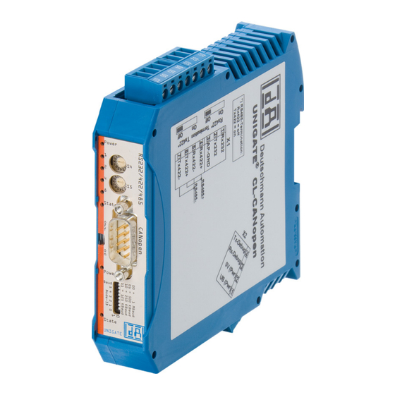
- Page 1 Instruction Manual Universal Fieldbus-Gateway ® UNIGATE CL - CANopen Deutschmann Automation GmbH & Co. KG www.deutschmann.com | wiki.deutschmann.de...
- Page 2 Manual Art.-No.: V3608E...
-
Page 3: Table Of Contents
Deutschmann Automation GmbH & Co. KG Information on CE marking of the module ....8 EU Directive EMC ......8 Scope of application . - Page 4 Deutschmann Automation GmbH & Co. KG What can you do with a Script device? ....21 Independence of buses ......21 Further settings at the Gateway .
- Page 5 Deutschmann Automation GmbH & Co. KG 11.5.1.5 Example: Force multiple coils FC 15 ......35 11.5.1.6 Example: Preset multiple register FC16 ..... . . 36 11.6 Protocol „Universal Modbus RTU Master“...
- Page 6 Deutschmann Automation GmbH & Co. KG 17 Error handling ......56 ®...
- Page 7 We would be pleased to receive any improvement proposals which you may have. Copyright Copyright (C) Deutschmann Automation GmbH & Co. KG 1997 – 2022. All rights reserved. This document may not be passed on nor duplicated, nor may its contents be used or disclosed unless expressly permitted.
-
Page 8: Information On Ce Marking Of The Module
The EU Declarations of Conformity are available at the following location for perusal by the responsible authorities in accordance with the EU Directive, Article 10: Deutschmann Automation GmbH & Co. KG, Carl-Zeiss-Straße 8, 65520 Bad Camberg, Ger- many. Scope of application The modules are designed for use in the industrial sector and comply with the following requirements. -
Page 9: Information For The Machine Manufacturers
Deutschmann Automation GmbH & Co. KG Information for the machine manufacturers Information for the machine manufacturers Introduction ® The UNIGATE module does not constitute a machine as defined by the EU "Machinery“ Directive. Consequently, the module does not have a Declaration of Conformity in relation to the EU Machinery Directive. -
Page 10: Introduction
Introduction Deutschmann Automation GmbH & Co. KG Introduction ® ® ® The UNIGATE CL-CANopen module serves to adapt a serial port to CANopen . In this appli- ® cation, it functions as a Gateway and operates as CANopen Slave. It can be operated by any standard-compliant Master. -
Page 11: Unigate ® Cl Software Flow-Chart
Deutschmann Automation GmbH & Co. KG Introduction ® UNIGATE CL software flow-chart ® ® 23.2.22 UNIGATE fieldbus gateway UNIGATE CL - CANopen V. 3.7... -
Page 12: Unigate ® Block Diagram
Introduction Deutschmann Automation GmbH & Co. KG ® UNIGATE block diagram ® The following picture shows a typical UNIGATE -module design. ® UNIGATE application diagram The following graph shows a typical connection scheme. ® ® ® UNIGATE fieldbus gateway UNIGATE CL - CANopen V. -
Page 13: Operation Modes Of The Gateway
Deutschmann Automation GmbH & Co. KG Operation modes of the Gateway Operation modes of the Gateway Configuration mode (config mode) The configuration mode serves to configure the Gateway. The following adjustments are possible in this mode. • Loading a Script •... -
Page 14: Data Exchange Mode
Operation modes of the Gateway Deutschmann Automation GmbH & Co. KG Data exchange mode The Gateway has to be in the data exchange mode, so that a data exchange between the RS-side of the Gateway and the fieldbus is possible. As long as the Gateway is not in the config- uration mode or the test mode, the data exchange mode is active. -
Page 15: Rs-Interface
Deutschmann Automation GmbH & Co. KG RS-interface RS-interface ® RS-interfaces at the UNIGATE ® ® The UNIGATE CL - CANopen has the interfaces RS232, RS422 and RS485 available. The hardware always features a DEBUG-interface, see chapter 7. ® Buffer sizes at the UNIGATE ®... -
Page 16: Ssi-Interface
SSI-interface Deutschmann Automation GmbH & Co. KG SSI-interface ® The UNIGATE also supports the connection of applications or products, that communicate via SSI. Initiation of the SSI-interface The configuration of the SSI-interface is executed in the config mode with the WINGATE soft- ware, Protocol SSI. -
Page 17: Parameter Encoder Monitoring (Check Encoder)
Deutschmann Automation GmbH & Co. KG SSI-interface 6.2.4 Parameter Encoder monitoring (Check Encoder) An encoder monitoring can be activated via the parameter "Check encoder", as long as the used SSI-encoder supports this function. After the last read encoder bit it is verified if the data line is ®... -
Page 18: The Debug-Interface
The Debug-interface Deutschmann Automation GmbH & Co. KG The Debug-interface Overview of the Debug-interface ® The UNIGATE features a Debug-interface, that allows a step-by-step processing of a Script. Normally this interface is only required for the development of a Script. -
Page 19: Mode Of Operation Of The System
Communication can be split into seven layers, Layer 1 to Layer 7, in accordance with the ISO/OSI model. The Deutschmann Automation Gateways convert Layers 1 and 2 of the customized bus system (RS485 / RS232 / RS422) to the corresponding Fieldbus system. Layers 3 to 6 are blank, and Layer 7 is converted in accordance with chapter 8.3. -
Page 20: Possible Data Lengths
Mode of operation of the system Deutschmann Automation GmbH & Co. KG Possible data lengths ® The table below shows the maximum transferable data in CANopen Input data max. 255 bytes Variable: maximum value in this case Output data max. 255 bytes... -
Page 21: Generating A Script
Deutschmann Automation GmbH & Co. KG Generating a Script Generating a Script What is a Script? A Script is a sequence of commands, that are executed in that exact order. Because of the fact that also mechanisms are given that control the program flow in the Script it is also possible to assemble more complex processes from these simple commands. -
Page 22: The Use Of The Protocol Developer
Generating a Script Deutschmann Automation GmbH & Co. KG configuration of the values in WINGATE is the following: After an update of the Script these val- ues remain untouched, i. e. the settings that were made once are still available after a change of the Script. -
Page 23: Script Processing Times
Deutschmann Automation GmbH & Co. KG Generating a Script Error = (abs(9615.38 - 9600) / 9600) * 100 = 0.16% In practise errors below 2% can be tolerated! In the following please find a listing of baud rates at a 40 MHz-crystal frequency with the corre-... - Page 24 Generating a Script Deutschmann Automation GmbH & Co. KG • Do not unnecessarily extend the data length at the Fieldbus side. Especially at acyclical bus data, if possible do only send them when changes were made. The data length at buses that are configured to a fixed length (e.
-
Page 25: Implemented Protocols With Universal Script - Configuration
Deutschmann Automation GmbH & Co. KG Implemented protocols with Universal Script - Configuration 10 Implemented protocols with Universal Script - Configuration ® UNIGATE CL is supplied with the Script “Universal Script Deutschmann“. The configuration of the protocols is carried out by means of the software WINGATE. See also "Instructions UNI- ®... -
Page 26: Protocol: Universal 232
Implemented protocols with Universal Script - protocols application Deutschmann Automation GmbH & Co. KG 11.2 Protocol: Universal 232 The protocol designation "Universal 232" and the relation to the "RS232-interface" in the description have eveloped over the years. The protocol also works with RS422 and RS485 though! 11.2.1 Data structure... -
Page 27: Timeout
Deutschmann Automation GmbH & Co. KG Implemented protocols with Universal Script - protocols application 11.2.3.3 Timeout If the end character is set to "FF", the value that was set in the RX_Timeout parameter is acti- vated and the time entered there is waited for with serial reception, or triggered for new charac- ters. -
Page 28: Protocol: 3964(R)
Implemented protocols with Universal Script - protocols application Deutschmann Automation GmbH & Co. KG 11.3 Protocol: 3964(R) The 3964 protocol is used to transfer data between two serial devices. One partner must be a high-priority partner and the other must be a low-priority partner in order to resolve initialisation conflicts. -
Page 29: Retries
Deutschmann Automation GmbH & Co. KG Implemented protocols with Universal Script - protocols application If the 3964 R driver receives data, it monitors arrival of the individual characters within period tz. If no character is received within the timeout time, the protocol terminates transfer. No acknowledgement is sent to the coupling partner. -
Page 30: Data Structure
Implemented protocols with Universal Script - protocols application Deutschmann Automation GmbH & Co. KG The mode "Modbus request on demand" necessitates the first byte in the fieldbus containing a trigger byte (see chapter 14). This byte is not transferred to the Modbus and serves only to start a Modbus transmission. -
Page 31: Data Structure
Deutschmann Automation GmbH & Co. KG Implemented protocols with Universal Script - protocols application 11.4.3.2 Data structure 11.4.3.3 Communication sequence The gateway always acts as the Slave with respect to the fieldbus and also acts as Slave at the Modbus end. A data exchange is always initiated by the MODBUS-Master via the RS-interface. If... -
Page 32: Example: Fc1 + Fc2
Implemented protocols with Universal Script - protocols application Deutschmann Automation GmbH & Co. KG Data structure 11.5.1.1 Example: FC1 + FC2 A Modbus Master (external device) sends a request with function code 1 or 2. Note: Modbus Master Request Address (High + Low) Address request 01 .. -
Page 33: Example: Fc3 (Read Holding Register) + Fc4 (Read Input Register)
Deutschmann Automation GmbH & Co. KG Implemented protocols with Universal Script - protocols application ® UNIGATE sends response via RS232/485: [01] [02] [0a] [02] [03] [04] [05] [06] [07] [08] [00] [00] [00] [8f] [7a] 11.5.1.2 Example: FC3 (Read Holding Register) + FC4 (Read Input Register) ®... - Page 34 Implemented protocols with Universal Script - protocols application Deutschmann Automation GmbH & Co. KG With FC1 and the coil length = 80 (10 Bytes) a Modbus Master reads out the following data: The fieldbus output data is only updated if it’s triggered via a write command from the RS side.
-
Page 35: Example: Write Single Register Fc6
Deutschmann Automation GmbH & Co. KG Implemented protocols with Universal Script - protocols application The internal buffer reserves this value, which means it can be read back by the Master via FC1 Read Coil status: 11.5.1.4 Example: Write Single Register FC6 Modbus Master sends the value 1234H in Address 0008: ®... -
Page 36: Example: Preset Multiple Register Fc16
Implemented protocols with Universal Script - protocols application Deutschmann Automation GmbH & Co. KG Adr 0002 ... 004 was changed from Low to High The 1st row shows the fieldbus BEFORE the request: 1F 00 FF 03 04 05 06 07 FF 00 00 00 00 00 00 00 00 00 00 00 00 00 00 00 00 00 00 00 00 00... -
Page 37: Protocol „Universal Modbus Rtu Master
Deutschmann Automation GmbH & Co. KG Implemented protocols with Universal Script - protocols application 11.6 Protocol „Universal Modbus RTU Master“ ® The UNIGATE is Modbus-Master on the Application side. 11.6.1 Data structure Fieldbus side (e.g. PROFIBUS): Applies to In and Out... -
Page 38: Configuration: Via Wingate Since Wcf Datei Version 396
Implemented protocols with Universal Script - protocols application Deutschmann Automation GmbH & Co. KG 11.6.3 Configuration: via Wingate since wcf Datei Version 396 Parameter Name value range Explanation Modbus Timeout (10ms) 1 ... 255 (10ms ... 2550ms) Max. Waiting time for the "Response" before an error 9 is generated by timeout. -
Page 39: Example: Read Coil Status Fc1
Deutschmann Automation GmbH & Co. KG Implemented protocols with Universal Script - protocols application 11.6.3.1 Example: Read coil status FC1 Configuration Data content Modbus Slave ® UNIGATE reads Address 5 + 6 and copies it into the 6. byte of the output buffer. -
Page 40: Example: Read Input Status Fc2
Implemented protocols with Universal Script - protocols application Deutschmann Automation GmbH & Co. KG AD 07 00 00 00 00 00 00 01 00 00 00 00 00 00 00 AE 07 00 00 00 00 00 00 03 00 00 00 00 00 00 00 The modification can be seen here: Byte = Fieldbus Map Adr 6 (Wert = 0x01) =>... -
Page 41: Example: Read Multiple Register Fc3
Deutschmann Automation GmbH & Co. KG Implemented protocols with Universal Script - protocols application Here the content of the address 10009 is changed from 0 -> 1 In the following example only the "No. Of Points" is switched to 10. -
Page 42: Example: Read Input Registers Fc4
Implemented protocols with Universal Script - protocols application Deutschmann Automation GmbH & Co. KG Thereby the addressed slave holds the following data in its registers.: register address value(hex) 40000 0x0000 40001 0x0202 40002 0x0303 40003 0x0000 40004 0x0000 register = 1 Word = 2 Byte In the documentation of some applications, an Offset + 1 at the address is assu- med. -
Page 43: Example: Preset Single Register Fc6
Deutschmann Automation GmbH & Co. KG Implemented protocols with Universal Script - protocols application 11.6.3.6 Example: Preset single register FC6 Configuration ® SPS sends to UNIGATE 01 00 00 00 00 00 00 FF23 00 FF 00 00 00 00 00 FF 00 00 00 00 00 00 00 00 00 00 00 00 00 ... -
Page 44: Example: Preset Multiple Register Fc16
Implemented protocols with Universal Script - protocols application Deutschmann Automation GmbH & Co. KG Storage content of Modbus Slave after response: Please keep in mind that No. Of coild = 10, hence, only the lower bit in address 0011 is written at the value 0x05. -
Page 45: Protocol „Universal Modbus Ascii Master/Slave
Deutschmann Automation GmbH & Co. KG Implemented protocols with Universal Script - protocols application 11.7 Protocol „Universal Modbus ASCII Master/Slave“ ® The fieldbus data exchange for Modbus ASCII is identical with RTU. The UNIGATE automati- cally transmits the data in ASCII format on the serial side. -
Page 46: Implemented Protocols With Universal Script - Protocols Canopen/Can Layer 2
Implemented Protocols with Universal Script - Protocols CANopen/CAN Layer 2 Deutschmann Automation GmbH & Co. KG 12 Implemented Protocols with Universal Script - Protocols CANopen/CAN Layer 2 Below you will find the descriptions of the implemented protocols that can be used for the bus. -
Page 47: Protocol Can 2.0B
Deutschmann Automation GmbH & Co. KG Implemented Protocols with Universal Script - Protocols CANopen/CAN Layer 2 Example: In this example only the COB-ID´s „0000“ (hex), „0181“ (hex), „0201“ (hex) and „0080“ (hex) are processed, i.e. transferred to the fieldbus. 12.4 Protocol CAN 2.0B A maximum of 13 Byte of data are displayed on the fieldbus side (1 Byte frame info, 4 Byte COB-ID, 8 Byte payload). -
Page 48: Protocol Can 2.0B With Id-Filter
Implemented Protocols with Universal Script - Protocols CANopen/CAN Layer 2 Deutschmann Automation GmbH & Co. KG Data display on the fieldbus side (SPS receives from CAN) “29 Bit Mode”: 1. Byte number of received data from CAN (Low Nibble) Bit 7 (MSB) = 1 => 29Bit Frame received Bit 6 = RTR Bit 5 …... -
Page 49: Delivery Status (Factory Setting)
Deutschmann Automation GmbH & Co. KG Delivery status (factory setting) 13 Delivery status (factory setting) ® On delivery, the UNIGATE is set to the CANopen protocol (default) on the fieldbus side and to the Transparent protocol on the application side. -
Page 50: Hardware Ports, Switches And Leds
Hardware ports, switches and LEDs Deutschmann Automation GmbH & Co. KG 16 Hardware ports, switches and LEDs 16.1 Device labeling Picture 1: Terminal labeling and termination Picture 2: Front panel: Rotary switches, DIP-switch, LEDs and termination CO In case the front panel should pop out it does not affect the device’s function or quality. -
Page 51: Connector Supply Voltage And Debug-Interface
Deutschmann Automation GmbH & Co. KG Hardware ports, switches and LEDs Rx 422- (485-) Receive signal Tx 422+ (485+) Transmit signal Tx 422- (485-) Transmit signal For the operation at a 485-interface the two pins labeled "485-" have to be connected together. -
Page 52: Leds
Hardware ports, switches and LEDs Deutschmann Automation GmbH & Co. KG 16.3 LEDs ® ® The Gateway UNIGATE CL - CANopen features 8 LEDs with the following significance: ® LED (Bus) Power green Supply voltage CANopen ® LED (Bus) State... -
Page 53: Led "Power
Deutschmann Automation GmbH & Co. KG Hardware ports, switches and LEDs ® CANopen ERROR LED (red) ® The CANopen Error LED indicates the status of the CAN physical layer and indicates errors due to missing CAN messages (SYNC, GUARD or HEARTBEAT). -
Page 54: Leds 1 / 2 / 4 / 8 (Error No. / Select Id)
Hardware ports, switches and LEDs Deutschmann Automation GmbH & Co. KG 16.3.5 LEDs 1 / 2 / 4 / 8 (Error No. / Select ID) If these 4 LEDs flash and LED “State“ simultaneously lights red, the error number is displayed in binary notation (conversion table, see Annex) in accordance with the table in chapter "Error... -
Page 55: Termination (Canopen ® )
Deutschmann Automation GmbH & Co. KG Hardware ports, switches and LEDs ® 16.4.3 Termination (CANopen ® If the Gateway is operated as the first or last physical device in the CANopen , there must be a bus termination at this Gateway. In order to do this, either a bus terminating resistor must be acti- vated in the connector or the resistor (220 ) integrated in the Gateway must be activated. -
Page 56: Error Handling
Error handling Deutschmann Automation GmbH & Co. KG 17 Error handling ® 17.1 Error handling at UNIGATE If the Gateway detects an error, the error is signalled by the “State“ LED lighting red and, simulta- neously, the error number being indicated by means of LEDs “Error No.“ as shown in the table below. - Page 57 Deutschmann Automation GmbH & Co. KG Error handling Error- LED8 LED4 LED2 LED1 Protocol Error description all Protocols No Universal script support all Protocols Unknown Protocols Modbus RTU Master Timeout-Modbus Slave Modbus ASCII Master Participant didn’t response in set time frame (response time).
-
Page 58: Installation Guidelines
Installation guidelines Deutschmann Automation GmbH & Co. KG 18 Installation guidelines 18.1 Installation of the module The module with the dimensions 23 x 117 x 111 mm (W x D x H) has been developed for switch cabinet use (IP 20) and can thus be mounted only on a standard mounting channel (deep DIN-rail to EN 50022). -
Page 59: Power Supply
Deutschmann Automation GmbH & Co. KG Installation guidelines Tightening torque: 0.2... 0.4 Nm 18.2.1.1 Power supply The device must be powered with 10..33 V DC. • Connect the supply voltage to the 4-pole plug-in screw terminal in accordance with the labelling on the device. -
Page 60: Shielding Of Lines
Installation guidelines Deutschmann Automation GmbH & Co. KG The table below allows you to read off the conditions for laying the line groups on the basis of the combination of the individual groups. Group A Group B Group C Group A... - Page 61 Deutschmann Automation GmbH & Co. KG Installation guidelines • Use metal cable clips to secure the shield braiding. The clips must surround the shield over a large area and must have good contact. • Downstream of the entry point of the line into the cabinet, connect the shield to a shielding bus.
-
Page 62: Canopen
CANopen® Deutschmann Automation GmbH & Co. KG ® 19 CANopen ® 19.1 Description CANopen ® This specification is based on the CiA Draft Standard 301 (DS301). ® CANopen supports the Standard CAN-frame with 11-bit Identifier. It is not required to support the extended frame with 29-bit Identifier. - Page 63 Deutschmann Automation GmbH & Co. KG CANopen® Use the following values for the parameters: CAN Layer 2 If you want to use CAN Layer 2, you can set a special Script initialization to access every CAN message without any Filter. Please note that the data format for ReadBus and WriteBus differs from other functionalities in this case.
-
Page 64: Canopen ® V4
CANopen® Deutschmann Automation GmbH & Co. KG ® 19.1.2 CANopen Additional supported functions: • Heartbeat • Dynamic mapping • Onswich message The following example can be found in the file folder “example“ after the installation of the soft- ware “Protocol Developer“ (this example gives a detailed description of the initialization): •... -
Page 65: Technical Data
Deutschmann Automation GmbH & Co. KG Technical data 20 Technical data 20.1 Device data The technical data of the module is given in the table below. No. Parameter Data Explanations Location Switch cabinet DIN-rail mounting Enclosure IP20 Protection against foreign bodies... -
Page 66: Interface Data
Technical data Deutschmann Automation GmbH & Co. KG 20.1.1 Interface data The table below lists the technical data of the interfaces and ports on the device. The data has been taken from the corresponding Standards. Interface designation RS232-C RS485/RS422 ®... -
Page 67: Commissioning Guide
Deutschmann Automation GmbH & Co. KG Commissioning guide 21 Commissioning guide 21.1 Note ® Only trained personnel following the safety regulations may commission the UNIGATE 21.2 Components ® You will require the following components to commission the UNIGATE ® •... -
Page 68: Commissioning
Commissioning guide Deutschmann Automation GmbH & Co. KG 21.5 Commissioning It is essential that you perform the following steps during commissioning in order to ensure that the module operates correctly: ® 21.6 Setting the CANopen address and baud rate ®... -
Page 69: Servicing
Deutschmann Automation GmbH & Co. KG Servicing 22 Servicing Should questions arise that are not covered in this manual you can find further information in our • FAQ/Wiki area on our homepage www.deutschmann.com or directly in our Wiki on www.wiki.deutschmann.de If your questions are still unanswered please contact us directly. -
Page 70: Annex
Annex Deutschmann Automation GmbH & Co. KG 23 Annex 23.1 Explanations of the abbreviations General Product group CL (Compact Line) Product group CM (CANopen Line) Product group CX Product group EL (Ethernet Line) Product group FC (Fast Connect) Galvanic separation RS-side... -
Page 71: Hexadecimal Table
Deutschmann Automation GmbH & Co. KG Annex product) ® PBDPX ProfibusDP-version X (see comparison table UNIGATE IC for the respective product) PBDPV0 = ProfibusDPV0 PBDPV1 = ProfibusDPV1 Serial RS232/485/422 23.2 Hexadecimal table Decimal Binary 0000 0001 0010 0011 0100 0101...
Need help?
Do you have a question about the UNIGATE CL-CANopen and is the answer not in the manual?
Questions and answers