
Related Manuals for AXIOMTEK CAPA520


Summary of Contents for AXIOMTEK CAPA520
- Page 1 CAPA520 ® Generation Intel Core Processor Family 3.5” Board User’s Manual...
- Page 2 Axiomtek does not make any commitment to update the information in this manual. Axiomtek reserves the right to change or revise this document and/or product at any time without notice. No part of this document may be reproduced, stored in a retrieval system, or transmitted, in any form or by any means, electronic, mechanical, photocopying, recording, or otherwise, without the prior written permission of Axiomtek Co., Ltd.
-
Page 3: Esd Precautions
It discharges static electricity from your body. Wear a wrist-grounding strap, available from most electronic component stores, when handling boards and components. Trademarks Acknowledgments Axiomtek is a trademark of Axiomtek Co., Ltd. ® ® Intel and Celeron are trademarks of Intel Corporation. -
Page 4: Table Of Contents
Table of Contents Disclaimers ..................... ii ESD Precautions ................... iii Chapter 1 Introduction ..........1 Features ....................2 Specifications ..................2 Utilities ....................4 Chapter 2 Board and Pin Assignments ....5 Board Dimensions and Fixing Holes ..........5 Board Layout ..................7 Installing Fan .................. - Page 5 2.5.23 ZIO Expansion Connector (SCN3) ............24 Chapter 3 Hardware Description ......25 Microprocessors ................25 BIOS ....................25 System Memory ................. 25 I/O Port Address Map ................ 26 Interrupt Controller (IRQ) Map ............27 Memory Map ..................33 Chapter 4 AMI BIOS Setup Utility ......
- Page 6 This page is intentionally left blank.
-
Page 7: Chapter 1 Introduction
CAPA520 Intel Core Processor Family 3.5” Board Chapter 1 Introduction The CAPA520, a high performance 3.5” board, supports LGA1151 socket for 8 ® Generation Intel Core i7/ i5/ i3 processors with H310 (Q370 optional) chipsets. The board delivers outstanding system performance through high-bandwidth interfaces, multiple I/O functions for interactive applications and various embedded computing solutions. -
Page 8: Features
® CAPA520 Intel Core Processor Family 3.5” Board Features ® ® LGA1151 socket for 8 Generation Intel Core i7/ i5/ i3/ Celeron with TDP 35W processors H310 (Q370 optional) chipset 1 DDR4 SO-DIMM supports up to 32GB memory capacity ... - Page 9 ® CAPA520 Intel Core Processor Family 3.5” Board USB Interface Four USB ports on the rear I/O: H310 chipset: Three for USB 3.0 and one for USB 2.0. Q370 chipset (optional): Three for USB 3.1 Gen2 and one for USB 2.0.
-
Page 10: Utilities
® CAPA520 Intel Core Processor Family 3.5” Board Utilities Chipset and graphics driver ® Ethernet driver (Intel i211AT and i219LM) Audio driver (optional for AX93A22) Introduction... -
Page 11: Board And Pin Assignments
® CAPA520 Intel Core Processor Family 3.5” Board Chapter 2 Board and Pin Assignments Board Dimensions and Fixing Holes Top View Board and Pin Assignments... - Page 12 ® CAPA520 Intel Core Processor Family 3.5” Board Bottom View Side View Board and Pin Assignments...
-
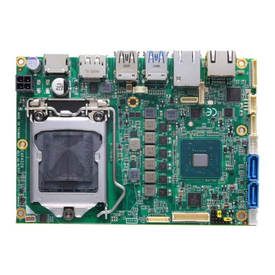
Page 13: Board Layout
® CAPA520 Intel Core Processor Family 3.5” Board Board Layout Top View Side View Board and Pin Assignments... - Page 14 ® CAPA520 Intel Core Processor Family 3.5” Board Bottom View Board and Pin Assignments...
-
Page 15: Installing Fan
® CAPA520 Intel Core Processor Family 3.5” Board Installing Fan The processor needs specially designed heatsink and fan assembly to cool down and ensure sufficient air flow inside your system. After applying thermal grease on the processor and installing it on the socket, please place heatsink and fan assembly on top of the processor. -
Page 16: Jumper And Switch Settings
And remove jumper clip from 2 jumper pins to open. Below illustration shows how to set up jumper. Properly configure jumper and switch settings on the CAPA520 to meet your application purpose. Below you can find a summary table of jumper, switch and onboard default settings. -
Page 17: Lvds +3.3V/+5V/+12V Voltage Selection (Jp1)
® CAPA520 Intel Core Processor Family 3.5” Board 2.4.1 LVDS +3.3V/+5V/+12V Voltage Selection (JP1) This is a 2x3-pin (pitch=2.0mm) jumper. The board supports voltage selection for flat panel displays. Use JP1 to set LVDS connector (see section 2.5.6) pin 1~6 VCCM to +3.3V, +5V or +12V. -
Page 18: Connectors
® CAPA520 Intel Core Processor Family 3.5” Board Connectors Signals go to other parts of the system through connectors. Loose or improper connection might cause problems, please make sure all connectors are properly and firmly connected. Here is a summary table of connectors on the hardware. -
Page 19: Front Panel Connector (Cn1)
® CAPA520 Intel Core Processor Family 3.5” Board 2.5.1 Front Panel Connector (CN1) This is a 2x6-pin header (pitch=2.0mm) for front panel interface. 8 10 12 Signal Signal BUZZER- BUZZER+ PWR_PSON 9 11 PWRLED- PWRLED+ PWRSW- PWRSW+ HW RST- HW RST+... -
Page 20: Smbus Connector (Cn2)
® CAPA520 Intel Core Processor Family 3.5” Board 2.5.2 SMBus Connector (CN2) This is a 1x3-pin (pitch=1.25mm) wafer connector fully compliant with JST B3B-PH-K-S for SMBus interface. The SMBus (System Management Bus) is a simple bus for the purpose of lightweight communication. -
Page 21: Displayport Connector (Cn4)
® CAPA520 Intel Core Processor Family 3.5” Board 2.5.4 DisplayPort Connector (CN4) The DisplayPort interface is available through connector CN4. Signal DPB_LANE0 DPB_LANE0# DPB_LANE1 DPB_LANE1# DPB_LANE2 DPB_LANE2# DPB_LANE3 DPB_LANE3# Detect Pin DPB_AUX DPB_AUX# DPB_HPD +3.3V 2.5.5 Inverter Connector (CN5) This is an 8-pin (pitch=1.25mm) connector fully compliant with Hirose DF13-8P-1.25V for inverter. -
Page 22: Lvds Connector (Cn6)
® CAPA520 Intel Core Processor Family 3.5” Board 2.5.6 LVDS Connector (CN6) This board has one 2x20-pin (pitch=1.0mm) connector for LVDS LCD. It is strongly recommended to use the matching connector, JST SHDR-40VS-B, for LVDS interface. Pin 1~6 VCCM can be set to +3.3V, +5V or +12V using JP1 (see section 2.4.1). Please note that when making LVDS cable, the pin 2 of JST SHDR-40VS-B connector should match the pin 1 of CN1. - Page 23 ® CAPA520 Intel Core Processor Family 3.5” Board 24-bit single channel 18-bit dual channel Pin Signal Pin Signal Pin Signal Pin Signal VCCM VCCM VCCM VCCM VCCM VCCM VCCM VCCM VCCM VCCM VCCM VCCM N.C. N.C. LVDS_HPD LVDS_HPD 10 GND 10 GND 11 N.C...
-
Page 24: Ethernet Ports (Cn7 And Cn8)
® CAPA520 Intel Core Processor Family 3.5” Board 2.5.7 Ethernet Ports (CN7 and CN8) ® The board has two RJ-45 Ethernet connectors; CN7 for LAN1 with Intel i219LM and ® CN8 for LAN2 with Intel i211AT. Ethernet connection can be established by plugging one end of the Ethernet cable into this connector and the other end (phone jack) to a 1000/100/10-Base-T hub. -
Page 25: Usb 3.0 Port (Cn10)
® CAPA520 Intel Core Processor Family 3.5” Board 2.5.9 USB 3.0 Port (CN10) This is a Universal Serial Bus (compliant with USB 3.0) connector on the rear I/O for installing USB peripherals such as keyboard, mouse, scanner, etc. Signal Signal... -
Page 26: Sata Connectors (Cn13 And Cn14)
® CAPA520 Intel Core Processor Family 3.5” Board 2.5.12 SATA Connectors (CN13 and CN14) These Serial Advanced Technology Attachment (Serial ATA or SATA) connectors are for high-speed SATA interfaces. They are computer bus interfaces for connecting to devices such as hard disk drive(s). -
Page 27: Com1 Wafer Connector (Cn17)
® CAPA520 Intel Core Processor Family 3.5” Board 2.5.15 COM1 Wafer Connector (CN17) This is a 1x9-pin (pitch=1.25mm) wafer fully compliant with MOLEX 53047 for serial port interface. The pin assignments of RS-232/422/485 are listed in table below. If you need COM1 to support RS-422 or RS-485, please refer to BIOS setting in section 4.4. -
Page 28: Audio Wafer Connector (Cn20)
® CAPA520 Intel Core Processor Family 3.5” Board 2.5.18 Audio Wafer Connector (CN20) This is an 8-pin (pitch=1.0mm) wafer connector fully compliant with JST BM08B-SRSS-TB for HD audio interface. It is suggested to connect AX93A22 audio I/O board to have Mic in/Line in and Line out. -
Page 29: Full-Size Pci-Express Mini Card Connector (Scn1)
® CAPA520 Intel Core Processor Family 3.5” Board 2.5.21 Full-size PCI-Express Mini Card Connector (SCN1) This is a full-size PCI-Express Mini Card connector complying with PCI-Express Mini Card Spec. V1.2. It supports either PCI-Express, USB 2.0 or SATA (mSATA). Signal... -
Page 30: Sim Card Wafer Connector (Scn2)
® CAPA520 Intel Core Processor Family 3.5” Board 2.5.22 SIM Card Wafer Connector (SCN2) The SCN2 is a 6-pin (pitch=1.0mm) wafer connector fully compliant with JST B6B-PH-K-S for SIM Card interface. AX93A19 SIM I/O board is suggested to use for SCN2 to have SIM card slot. -
Page 31: Chapter 3 Hardware Description
Make sure all correct settings are arranged for your installed microprocessor to prevent the CPU from damages. BIOS The CAPA520 uses AMI Plug and Play BIOS with a single 256Mbit SPI Flash. System Memory The CAPA520 supports one 260-pin DDR4 SO-DIMM socket for maximum memory capacity up to 32GB DDR4 SDRAMs. -
Page 32: I/O Port Address Map
® CAPA520 Intel Core Processor Family 3.5” Board I/O Port Address Map Hardware Description... -
Page 33: Interrupt Controller (Irq) Map
® CAPA520 Intel Core Processor Family 3.5” Board Interrupt Controller (IRQ) Map The interrupt controller (IRQ) mapping list is shown as follows: Hardware Description... - Page 34 ® CAPA520 Intel Core Processor Family 3.5” Board Hardware Description...
- Page 35 ® CAPA520 Intel Core Processor Family 3.5” Board Hardware Description...
- Page 36 ® CAPA520 Intel Core Processor Family 3.5” Board Hardware Description...
- Page 37 ® CAPA520 Intel Core Processor Family 3.5” Board Hardware Description...
- Page 38 ® CAPA520 Intel Core Processor Family 3.5” Board Hardware Description...
-
Page 39: Memory Map
® CAPA520 Intel Core Processor Family 3.5” Board Memory Map The memory mapping list is shown as follows: Hardware Description... - Page 40 ® CAPA520 Intel Core Processor Family 3.5” Board This page is intentionally left blank. Hardware Description...
-
Page 41: Ami Bios Setup Utility
® CAPA520 Intel Core Processor Family 3.5” Board Chapter 4 AMI BIOS Setup Utility The AMI UEFI BIOS provides users with a built-in setup program to modify basic system configuration. All configured parameters are stored in a flash chip to save the setup information whenever the power is turned off. - Page 42 ® CAPA520 Intel Core Processor Family 3.5” Board Hot Keys Description Left/Right The Left and Right <Arrow> keys allow you to select a setup screen. The Up and Down <Arrow> keys allow you to select a setup screen or ...
-
Page 43: Main Menu
® CAPA520 Intel Core Processor Family 3.5” Board Main Menu When you first enter the setup utility, you will enter the Main setup screen. You can always return to the Main setup screen by selecting the Main tab. System Time/Date can be set up as described below. -
Page 44: Advanced Menu
® CAPA520 Intel Core Processor Family 3.5” Board Advanced Menu The Advanced menu also allows users to set configuration of the CPU and other system devices. You can select any of the items in the left frame of the screen to go to the sub menus: ►... - Page 45 A description of the selected item appears on the right side of the screen. For items marked with “”, please press <Enter> for more options. Serial Port 1 Configuration Use this item to set parameters related to serial port 1 (see section 2.5.14) on CAPA520. AMI BIOS Setup Utility...
- Page 46 Serial Port 1 Configuration Serial Port Enable or disable serial port 1 on CAPA520. The optimal setting for onboard F81803 SIO address is 3F8h and for interrupt request address is IRQ4. COM Port Type Use this item to set RS-232/422/485 communication mode.
- Page 47 ® CAPA520 Intel Core Processor Family 3.5” Board Hardware Monitor This screen monitors hardware health status. This screen displays the temperature of system and CPU, fan speed in RPM and system voltages (+3.3VSB/+5VSB and +3.3V/+5V). Smart Fan Function Enable or disable Smart Fan control function. Once enabled, you will be able to go further for Smart Fan Mode Configuration, see image below.
- Page 48 ® CAPA520 Intel Core Processor Family 3.5” Board ACPI Settings ACPI Sleep State Select S3 (Suspend to RAM) as ACPI sleep state the system will enter when suspend button is pressed. AMI BIOS Setup Utility...
- Page 49 ® CAPA520 Intel Core Processor Family 3.5” Board CPU Configuration This screen shows the CPU Configuration. Intel (VMX) Virtualization Technology Enable or disable Intel Virtualization Technology. When enabled, a VMM (Virtual Machine Mode) can utilize the additional hardware capabilities. It allows a platform to run multiple operating systems and applications independently, hence enabling a single computer system to work as several virtual systems.
- Page 50 ® CAPA520 Intel Core Processor Family 3.5” Board SATA Configuration During system boot up, BIOS automatically detects the presence of SATA devices. In the SATA Configuration menu, you can see the hardware currently installed in SATA ports. SATA Controller(s) Enable or disable the SATA Controller feature.
- Page 51 ® CAPA520 Intel Core Processor Family 3.5” Board PCH-FW Configuration This screen displays ME Firmware information. USB Configuration USB Devices Display all detected USB devices. AMI BIOS Setup Utility...
- Page 52 This option appears only if a ZIO module is installed. BIOS will auto-detect all supported functions and you can use it to change settings on the ZIO module. The CAPA520 supports the following ZIO expansion modules: AX93262, AX93285, AX93291, AX93295 and AX93A20.
- Page 53 ® CAPA520 Intel Core Processor Family 3.5” Board Onboard Device Configuration\Onboard DIO Configuration DIO Modification Enable or disable digital I/O modification. The default is Disabled. Once it is enabled, you can load manufacture default and access to the DIO status sub screen to set output or input.
- Page 54 ® CAPA520 Intel Core Processor Family 3.5” Board DIO port 1-8 Module Device Configuration\Module Super IO Configuration This screen is available only if a ZIO module with serial ports is connected. For items marked with “”, please press <Enter> for more options.
- Page 55 ® CAPA520 Intel Core Processor Family 3.5” Board Module Super IO Configuration You can use this screen to select options for NCT6627 Super IO Configuration, and change the value of the selected option. A description of selected item appears on the right side of the screen.
- Page 56 ® CAPA520 Intel Core Processor Family 3.5” Board Serial Port 1 Configuration Serial Port Enable or disable serial port 1 on ZIO module. The optimal setting for base I/O address is 240h and for interrupt request address is IRQ10.
- Page 57 ® CAPA520 Intel Core Processor Family 3.5” Board Serial Port 2 Configuration Serial Port Enable or disable serial port 2 on ZIO module. The optimal setting for base I/O address is 248h and for interrupt request address is IRQ3.
- Page 58 ® CAPA520 Intel Core Processor Family 3.5” Board Serial Port 3 Configuration Serial Port Enable or disable serial port 3 on ZIO module. The optimal setting for base I/O address is 250h and for interrupt request address is IRQ5.
- Page 59 ® CAPA520 Intel Core Processor Family 3.5” Board Serial Port 4 Configuration Serial Port Enable or disable serial port 4 on ZIO module. The optimal setting for base I/O address is 258h and for interrupt request address is IRQ6.
-
Page 60: Chipset Menu
® CAPA520 Intel Core Processor Family 3.5” Board Chipset Menu The Chipset menu allows users to change the advanced chipset settings. You can select any of the items in the left frame of the screen to go to the sub menus: ►... - Page 61 ® CAPA520 Intel Core Processor Family 3.5” Board System Agent (SA) Configuration This screen shows System Agent version information and provides function for specifying related parameters. Graphics Configuration Use this item to open graphics configuration sub screen. Memory Configuration Use this item to refer to information related to system memory.
- Page 62 ® CAPA520 Intel Core Processor Family 3.5” Board Primary IGFX Boot Display Select the video device which will be activated during POST (Power-On Self Test). The default is GOP Default. Secondary IGFX Boot Display When the Primary IGFX Boot Display is set a specific display, instead of GOP Default, Secondary IGFX Boot Display will be showed for selection.
- Page 63 ® CAPA520 Intel Core Processor Family 3.5” Board LVDS Control Enable or disable LVDS Control. LVDS Panel Type After LVDS control is enabled, the LVDS Panel Type is showed for selection. Select the appropriate LVDS panel resolution by options in image above.
- Page 64 ® CAPA520 Intel Core Processor Family 3.5” Board Brightness Setting After LVDS control is enabled, the Brightness Setting is showed for selection. It allows user to adjust the brightness level of the LVDS panel. Range: 0~255 Default: 255 Memory Configuration This screen shows the system memory information.
-
Page 65: Security Menu
® CAPA520 Intel Core Processor Family 3.5” Board Security Menu The Security menu allows users to change the security settings for the system. Administrator Password. Set administrator password. User Password Set user password. AMI BIOS Setup Utility... -
Page 66: Boot Menu
® CAPA520 Intel Core Processor Family 3.5” Board Boot Menu The Boot menu allows users to change boot options of the system. Setup Prompt Timeout Number of seconds to wait for setup activation key. 65535(0xFFFF) means indefinite waiting. ... -
Page 67: Save & Exit Menu
® CAPA520 Intel Core Processor Family 3.5” Board Save & Exit Menu The Save & Exit menu allows users to load your system configuration with optimal or fail-safe default values. Save Changes and Exit When you have completed the system configuration changes, select this option to leave Setup and return to Main Menu. - Page 68 ® CAPA520 Intel Core Processor Family 3.5” Board Discard Changes Select this option to quit Setup without making any permanent changes to the system configuration. Select Discard Changes from the Save & Exit menu and press <Enter>. Select Yes to discard changes.
-
Page 69: Appendix A Watchdog Timer
® CAPA520 Intel Core Processor Family 3.5” Board Appendix A Watchdog Timer A.1 About Watchdog Timer Software stability is major issue in most application. Some embedded systems are not watched by operator for 24 hours. It is usually too slow to wait for someone to reboot when computer hangs. -
Page 70: A.3 Sample Program
® CAPA520 Intel Core Processor Family 3.5” Board A.3 Sample Program Assembly sample code : ;Enable WDT: dx,2Eh al,87 ;Un-lock super I/O dx,al dx,al ;Select Logic device: dx,2Eh al,07h dx,al dx,2Fh al,07h dx,al ;Enable WDT base address: dx,2Eh al,30h dx,al... - Page 71 ® CAPA520 Intel Core Processor Family 3.5” Board If N=79h, the time base is set to minute. M = time value 00: Time-out disable 01: Time-out occurs after 1 minute 02: Time-out occurs after 2 minutes 03: Time-out occurs after 3 minutes...
- Page 72 ® CAPA520 Intel Core Processor Family 3.5” Board This page is intentionally left blank. Watchdog Timer...
-
Page 73: Appendix B Digital I/O
® CAPA520 Intel Core Processor Family 3.5” Board Appendix B Digital I/O B.1 About Digital I/O The digital I/O on CPU board has 8 bits. Each bit can be set to function as input or output by software programming. In default, all pins are pulled high with +5V level (according to main power). - Page 74 ® CAPA520 Intel Core Processor Family 3.5” Board Register 0: Input port register. This register is a read-only port. It reflects the incoming logic levels of the pins, regardless of whether the pin is defined as an input or an output by Register 3. Writes to this register have no effect.
- Page 75 ® CAPA520 Intel Core Processor Family 3.5” Board Register 3: Configuration register. This register configures the directions of the I/O pins. If a bit in this register is set, the corresponding port pin is enabled as an input with high-impedance output driver. If a bit in this register is cleared, the corresponding port pin is enabled as an output.
Need help?
Do you have a question about the CAPA520 and is the answer not in the manual?
Questions and answers