
Related Manuals for AXIOMTEK CAPA322


Summary of Contents for AXIOMTEK CAPA322
- Page 1 CAPA322 ® ® ® Intel Atom x6413E and Intel ® Celeron Processor J6412 and ® Celeron Processor N6210 3.5” Board User’s Manual...
-
Page 2: Disclaimers
Axiomtek does not make any commitment to update the information in this manual. Axiomtek reserves the right to change or revise this document and/or product at any time without notice. No part of this document may be reproduced, stored in a retrieval system, or transmitted, in any form or by any means, electronic, mechanical, photocopying, recording, or otherwise, without the prior written permission of Axiomtek Co., Ltd. -
Page 3: Esd Precautions
It discharges static electricity from your body. ◼ Wear a wrist-grounding strap, available from most electronic component stores, when handling boards and components. Trademarks Acknowledgments Axiomtek is a trademark of Axiomtek Co., Ltd. ® ® Intel and Celeron are trademarks of Intel Corporation. -
Page 4: Table Of Contents
Table of Contents Disclaimers ..................... ii ESD Precautions ................... iii Section 1 Introduction ..........1 Features ....................2 Specifications ..................2 Utilities Supported ................3 Section 2 Board and Pin Assignments ....1 Board Dimensions and Fixing Holes ..........1 Board Layout .................. - Page 5 Section 3 Hardware Description ......25 Microprocessors ................25 BIOS ....................25 System Memory ................. 25 I/O Port Address Map ................ 26 Interrupt Controller (IRQ) Map ............27 Memory Map ..................32 Section 4 AMI BIOS Setup Utility ......33 Starting ....................
- Page 6 This page is intentionally left blank.
-
Page 7: Introduction
CAPA322 3.5” Board Section 1 Introduction The CAPA322 is a 3.5” embedded board with Intel Celeron processor J6412 and N6210 & ® ® Atom ® x6413E processor that deliver outstanding system performance through high-bandwidth interfaces, multiple I/O functions for interactive applications and various embedded computing solutions. -
Page 8: Features
CAPA322 3.5” Board Features ® Celeron ® quad core J6412 processor (2.0GHz) and Celeron ® dual core N6210 ⚫ Intel processor (1.2GHz) Intel ® Atom ® quad core x6413E processor (1.5GHz) ⚫ ⚫ 1 DDR4 SO-DIMM supports up to 32GB memory capacity ⚫... -
Page 9: Utilities Supported
CAPA322 3.5” Board ⚫ Trusted Platform Module (TPM) ◼ Controller: ST ST33HTPH2X32AHD8 via SPI bus interface. ◼ Complies with TPM2.0 main and PC client specification. ⚫ Watchdog Timer ◼ Timeout value range is 1~65535 seconds. ⚫ Ethernet ® ◼ One RJ-45 LAN port: Intel I210-AT (I210-IT) supports 1000/100/10Mbps Gigabit/Fast Ethernet with Wake-on-LAN and PXE Boot ROM. - Page 10 CAPA322 3.5” Board This page is intentionally left blank. Introduction...
-
Page 11: Board And Pin Assignments
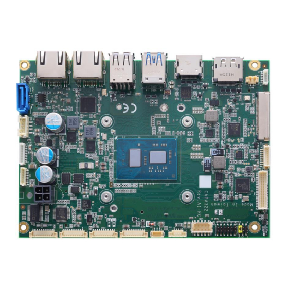
CAPA322 3.5” Board Section 2 Board and Pin Assignments Board Dimensions and Fixing Holes Top View Board and Pin Assignments... - Page 12 CAPA322 3.5” Board Bottom View Side View Board and Pin Assignment...
-
Page 13: Board Layout
CAPA322 3.5” Board Board Layout Top View Side View Board and Pin Assignments... - Page 14 CAPA322 3.5” Board Bottom View Board and Pin Assignment...
-
Page 15: Jumper And Switch Settings
And remove jumper clip from 2 jumper pins to open. Below illustration shows how to set up jumper. Properly configure jumper and switch settings on the CAPA322 to meet your application purpose. Below you can find a summary table of jumpers, switch and onboard default settings. -
Page 16: Lvds/Edp +3.3V/+5V/+12V Voltage Selection (Jp1)
CAPA322 3.5” Board 2.3.1 LVDS/eDP +3.3V/+5V/+12V Voltage Selection (JP1) The board supports voltage selection for flat panel displays. Use this jumper to set LVDS connector (CN4) pin 1~6 VCCM / eDP connector (CN9) pin 1~4 LCD_VCC to +3.3V, +5V or +12V level. To prevent hardware damage, before connecting please make sure that the input voltage of flat panel is correct. -
Page 17: Connectors
CAPA322 3.5” Board Connectors Signals go to other parts of the system through connectors. Loose or improper connection might cause problems, please make sure all connectors are properly and firmly connected. Here is a summary table of connectors on the hardware. -
Page 18: I 2 C Connector (Cn1)
CAPA322 3.5” Board 2.4.1 C Connector (CN1) This is a 4-pin (pitch=1.25mm) connector for I C interface which is compatible with SMBus. Signal C _CLK C _DATD C _ALERT_N 2.4.2 Fan Connector (CN2) Cooling fan interface is available through this connector. You can find fan speed within BIOS Setup Utility if fan is installed. -
Page 19: Front Panel Connector (Cn3)
CAPA322 3.5” Board 2.4.3 Front Panel Connector (CN3) This is a 2x6-pin header (pitch=2.0mm) for front panel interface. Signal Signal BUZZER- BUZZER+ PWR_PSON PWRLED- PWRLED+ PWRSW- PWRSW+ HW RST- HW RST+ HDDLED- HDDLED+ Internal Buzzer Pin 1(-) and 2(+) connect the internal buzzer cable. -
Page 20: Lvds Connector (Cn4)
CAPA322 3.5” Board 2.4.4 LVDS Connector (CN4) This board has a 2x20-pin connector which is compliant with JST SM40B-SRDS-G-TF for LVDS LCD interface. It is strongly recommended to use the matching connector JST SHDR-40VS-B. Pin 1~6 VCCM can be set to +3.3V, +5V or +12V by setting JP1 (see section 2.3.1). - Page 21 CAPA322 3.5” Board 24-bit single channel 18-bit dual channel Pin Signal Pin Signal Pin Signal Pin Signal VCCM VCCM VCCM VCCM VCCM VCCM VCCM VCCM VCCM VCCM VCCM VCCM 10 GND 10 GND 11 N.C 12 N.C 11 N.C 12 Channel B D0- 13 N.C...
-
Page 22: Hd Audio Wafer Connector (Cn5)
CAPA322 3.5” Board 2.4.5 HD Audio Wafer Connector (CN5) HD audio interface is available in an 8-pin (pitch=1.0mm) wafer connector fully compliant with JST BM08B-SRSS-TB. AX93A22 board is suggested to use in order to have Mic in/Line in and Line out. -
Page 23: Digital I/O Wafer Connector (Cn7)
CAPA322 3.5” Board 2.4.7 Digital I/O Wafer Connector (CN7) This is a 1x10-pin (pitch=1.0mm) wafer connector for digital interface which are fully compliant with JST BM10B-SRSS-TB. This 8-bit digital I/O meets requirements for a system customary automation control and can be configured to control cash drawers and sense warning signals from an Uninterrupted Power System (UPS), or perform store security control. -
Page 24: Edp Connector (Cn9) (Optional)
CAPA322 3.5” Board 2.4.9 eDP Connector (CN9) (Optional) The eDP interface is available through 40-pin connector (CN9), which is compliant with IPEX-20143. Pin 1~4 LCD_VCC can be set to +3.3V, +5V or +12V with JP1 (see section 2.3.1). Signal Signal... -
Page 25: Displayport++ Connector (Cn11)
CAPA322 3.5” Board 2.4.11 DisplayPort++ Connector (CN11) The DisplayPort++ interface is available through connector CN15. Signal DP_LANE0P DP_LANE0_N DP_LANE1_P DP_LANE1_N DP_LANE2_P DP_LANE2_N DP_LANE3_P DP_LANE3_N Detect Pin DP_AUX_P DP_AUX_N DP_HPDE +3.3V 2.4.12 HDMI Connector (CN12) The HDMI (High-Definition Multimedia Interface) is a compact digital interface which is capable of transmitting high-definition video and high-resolution audio over a single cable. -
Page 26: Atx Power Connector (Atx1/Atx2)
CAPA322 3.5” Board 2.4.13 ATX Power Connector (ATX1/ATX2) Steady and sufficient power can be supplied to all components on the board by connecting the power connector. Please make sure all components and devices are properly installed before connecting the power connector. -
Page 27: Com Wafer Connectors (Com1~Com4)
CAPA322 3.5” Board 2.4.15 COM Wafer Connectors (COM1~COM4) These are 9-pin (pitch=1.25mm) connectors, compliant with Molex 53047-0910. Use the matching cable 59380880250E is strongly recommended. COM1 and COM2 support RS-232/422/485 by BIOS selecting (see section 4.4). COM3 and COM4 support RS-232 only... -
Page 28: Ethernet Ports (Lan1 And Lan2)
CAPA322 3.5” Board 2.4.16 Ethernet Ports (LAN1 and LAN2) The board has two RJ-45 connectors: LAN1 and LAN2. Connection can be established by plugging one end of the Ethernet cable into: LAN1 (I210) and the other end (phone jack) to a 1000/100/10-Base-T hub. -
Page 29: Sata Connector (Sata1)
CAPA322 3.5” Board 2.4.17 SATA Connector (SATA1) This is a high-speed SATA (Serial Advanced Technology Attachment or Serial ATA) connector. It is a computer bus interface for connecting to devices such as hard disk drive. Signal SATA_TX1_P SATA_TX1_N SATA_RX1_N SATA_RX1_P 2.4.18... -
Page 30: Usb 2.0 Type A Port (Usb3)
CAPA322 3.5” Board 2.4.20 USB 2.0 Type A Port (USB3) This connector is compliant with a Universal Serial Bus type-A connector for installing versatile USB 2.0 compliant interface peripherals. Signal Signal USB VCC (+5V) USB VCC (+5V) Board and Pin Assignment... -
Page 31: Key E Connector (Scn2)
CAPA322 3.5” Board 2.4.21 M.2 Key E Connector (SCN2) The SCN2 is a M.2 2230 Key E connector. It is suggested to install the M.2 wireless module via PCIe x1 and USB 2.0 with 22mm width and 30mm length. Signal Signal +3.3V_SBY... -
Page 32: Full-Size Pci-Express Mini Card Connector (Scn3)
CAPA322 3.5” Board 2.4.22 Full-size PCI-Express Mini Card Connector (SCN3) This is a full-size PCI-Express Mini Card connector complying with PCI-Express Mini Card Spec. V1.2. Located on the bottom side of the board and supports either PCI-Express, USB or mSATA. Note that the factory default is mSATA, you can change to PCI Express by BIOS select (see BIOS Setup Utility: Advanced\Storage Configuration\ PCIE Mini Card Function in section 4.4). -
Page 33: Key B Connector (Scn4)
CAPA322 3.5” Board 2.4.23 M.2 Key B Connector (SCN4) The SCN2 is a M.2 Key B connector. It is suggested to install the M.2 cellular module with 30mm width and 42mm length or 30mm width and 50/52mm length. Signal Signal CONFIG_3 +3.3V_SBY... - Page 34 CAPA322 3.5” Board This page is intentionally left blank. Board and Pin Assignment...
-
Page 35: Hardware Description
CPU from damages. BIOS The CAPA322 uses AMI Plug and Play BIOS with a single 256Mbit SPI Flash. System Memory The CAPA332 supports one 260-pin DDR4 SO-DIMM sockets. The memory module comes in sizes of 4GB, 8GB, 16GB and 32GB. -
Page 36: I/O Port Address Map
CAPA322 3.5” Board I/O Port Address Map Hardware Description... -
Page 37: Interrupt Controller (Irq) Map
CAPA322 3.5” Board Interrupt Controller (IRQ) Map The interrupt controller (IRQ) mapping list is shown as follows: Hardware Description... - Page 38 CAPA322 3.5” Board Hardware Description...
- Page 39 CAPA322 3.5” Board Hardware Description...
- Page 40 CAPA322 3.5” Board Hardware Description...
- Page 41 CAPA322 3.5” Board Hardware Description...
-
Page 42: Memory Map
CAPA322 3.5” Board Memory Map The memory mapping list is shown as follows: Hardware Description... -
Page 43: Ami Bios Setup Utility
CAPA322 3.5” Board Section 4 AMI BIOS Setup Utility The AMI UEFI BIOS provides users with a built-in setup program to modify basic system configuration. All configured parameters are stored in a flash chip to save the setup information whenever the power is turned off. This section provides users with detailed description about how to set up basic system configuration through the AMI BIOS setup utility. - Page 44 CAPA322 3.5” Board Hot Keys Description → Left/Right The Left and Right <Arrow> keys allow you to select a setup screen. The Up and Down <Arrow> keys allow you to select a setup screen or Up/Down sub-screen. The <Enter> key allows you to display or change the setup option listed for a Enter particular setup item.
-
Page 45: Main Menu
CAPA322 3.5” Board Main Menu When you first enter the setup utility, you will enter the Main setup screen. You can always return to the Main setup screen by selecting the Main tab. System Time/Date can be set up as described below. -
Page 46: Advanced Menu
CAPA322 3.5” Board Advanced Menu The Advanced menu also allows users to set configuration of the CPU and other system devices. You can select any of the items in the left frame of the screen to go to the sub menus: ►... - Page 47 CAPA322 3.5” Board ⚫ F81216 Super IO Configuration You can use this screen to select options for Super IO Configuration, and change the value of the selected option. A description of the selected item appears on the right side of the screen.
- Page 48 CAPA322 3.5” Board ⚫ Serial Port 1~2 Configuration Serial Port 1~2 Enable or disable serial port 1~2. The optimal settings for base I/O address and for interrupt request address are: Serial port 1: 3F8h, IRQ4 Serial port 2: 3E8h, IRQ3 COM Port Type Use this item to set RS-232/422/485 communication mode.
- Page 49 CAPA322 3.5” Board ⚫ Serial Port 3~4 Configuration Serial Port 3~4 Enable or disable serial port 3~4. The optimal settings for base I/O address and for interrupt request address are: Serial port 3: 2F8h, IRQ11 Serial port 4: 2E8h, IRQ10...
- Page 50 CAPA322 3.5” Board ⚫ Ec DIO Configuration You can use this screen to select options for the 8-bit Digital I/O Configuration. A description of the selected item appears on the right side of the screen. For items marked with “”, please press <Enter> for more options.
- Page 51 CAPA322 3.5” Board Once it is enabled, you can load manufacture default and access to the DIO status sub screen to set output or input, see image below. DIO port 1-8 Select this option to open DIO status sub-screen. AMI BIOS Setup Utility...
- Page 52 CAPA322 3.5” Board ⚫ Hardware Monitor This screen displays hardware health status. This screen displays the temperature of system and CPU, fan speed in RPM and system voltages (VBAT, +3.3V_SBY and +5V). Smart Fan Mode Select Set Smart Fan mode. The default is Auto Mode. In Auto Mode, the fan spins at different speed depending on system temperature;...
- Page 53 CAPA322 3.5” Board ⚫ Trusted Computing This screen provides function for specifying the TPM settings. Security Device Support Enable or disable BIOS support for security device. Once the Security Device Support is enabled, you will see the following screen. AMI BIOS Setup Utility...
- Page 54 CAPA322 3.5” Board ⚫ CPU Configuration This screen shows the CPU Configuration. Intel Virtualization Technology Enable or disable Intel Virtualization Technology. When enabled, a VMM (Virtual Machine Mode) can utilize the additional hardware capabilities. It allows a platform to run multiple operating systems and applications independently, hence enabling a computer system to work as several virtual systems.
- Page 55 CAPA322 3.5” Board ⚫ Storage Configuration During system boot up, the BIOS automatically detects the presence of SATA devices. In the SATA Configuration menu, you can see all hardware currently installed in SATA ports. SATA Configuration Select to open SATA device setting sub-screen.
- Page 56 CAPA322 3.5” Board SATA Configuration SATA Controller(s) Enable or disable SATA device. SATA Mode Selection Determine how SATA controller(s) operate. AHCI (Advanced Host Controller Interface) AMI BIOS Setup Utility...
- Page 57 CAPA322 3.5” Board ⚫ USB Configuration USB Devices Display all detected USB devices. AMI BIOS Setup Utility...
-
Page 58: Chipset Menu
CAPA322 3.5” Board Chipset Menu The Chipset menu allows users to change the advanced chipset settings. ⚫ System Agent (SA) Configuration This screen allows users to configure System Agent (SA) parameters. LVDS Panel Device Enable or disable LVDS panel support. If enabled, you will see:... - Page 59 CAPA322 3.5” Board LVDS Panel Type Select the appropriate LVDS panel resolution, see image below. Backlight Control Backlight control options: PWM Inverted (backlight 100 to 0) PWM Normal (backlight 0 to 100) AMI BIOS Setup Utility...
-
Page 60: Security Menu
CAPA322 3.5” Board Security Menu The Security menu allows users to change the security settings for the system. ⚫ Administrator Password. Set administrator password. ⚫ User Password Set user password. AMI BIOS Setup Utility... - Page 61 CAPA322 3.5” Board Secure Boot Secure Boot feature is Active if Secure Boot is Enabled, Platform Key (PK) is enrolled and the System is in User mode. The mode change requires platform reset. Secure Boot Mode Secure Boot mode options : Standard or Custom. In Custom mode, Secure Boot Policy variables can be configured by a physically present user without full authentication.
-
Page 62: Boot Menu
CAPA322 3.5” Board Boot Menu The Boot menu allows users to change boot options of the system. ⚫ Setup Prompt Timeout Number of seconds to wait for setup activation key. 65535(0xFFFF) means indefinite waiting. ⚫ Bootup NumLock State Use this item to select the power-on state for the keyboard NumLock. -
Page 63: Save & Exit Menu
CAPA322 3.5” Board Save & Exit Menu The Save & Exit menu allows users to load your system configuration with optimal or fail-safe default values. ⚫ Save Changes and Exit When you have completed the system configuration changes, select this option to leave Setup and return to Main Menu. - Page 64 CAPA322 3.5” Board ⚫ Discard Changes Select this option to quit Setup without making any permanent changes to the system configuration. Select Discard Changes from the Save & Exit menu and press <Enter>. Select Yes to discard changes. ⚫ Restore Defaults It automatically sets all Setup options to a complete set of default settings when you select this option.
-
Page 65: Appendix A Watchdog Timer
CAPA322 3.5” Board Appendix A Watchdog Timer A.1 About Watchdog Timer After the system stops working for a while, it can be auto-reset by the watchdog timer. The integrated watchdog timer can be set up in the system reset mode by program. - Page 66 CAPA322 3.5” Board This page is intentionally left blank. Watchdog Timer...
-
Page 67: Appendix B Digital I/O
CAPA322 3.5” Board Appendix B Digital I/O B.1 About Digital I/O The onboard GPIO or digital I/O has 8 bits (DIO0~7). Each bit can be set to function as input or output by software programming. In default, all pins are pulled high with +5V level (according to main power).
Need help?
Do you have a question about the CAPA322 and is the answer not in the manual?
Questions and answers