Advertisement
Quick Links
Download this manual
See also:
User Manual
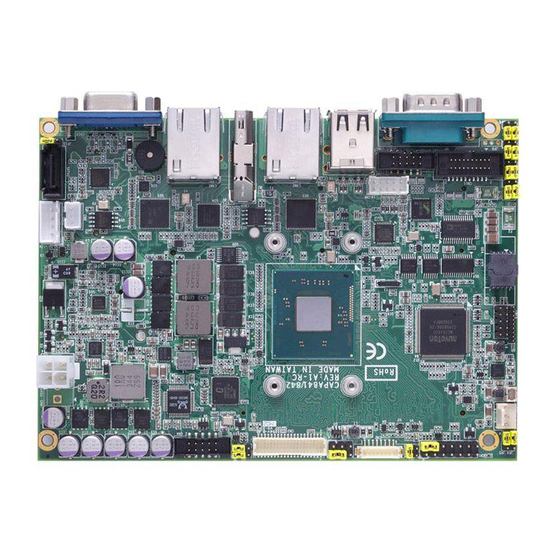
Side View
Quick Start
The basic procedures required to power on CAPA841/842:
(1). Require power at minimum 2.5A. Ensure that power supply is
OFF before connecting to CAPA841/842 and that all necessary
peripheral devices are plugged properly.
(2). Ensure all of the jumpers are at default settings; especially
JP10 (1-2 close).
(3). Firmly install DDR3L memory modules into connector
SSODIMM1 until fully seated.
Note: It must be DDR3L memory module.
(4). Firmly insert power to ATX1.
(5). Install a momentary on/off button/switch onto CN1, pin 9 and
10.
(6). Turn on the power supply.
(7). Press the on/off button/switch to power on CAPA841/842
4
9418E841010E
©
Copyright 2014 Axiomtek Co., Ltd.
Version A2 October 2014
Printed in Taiwan
CAPA841/842 Series Quick Installation Guide
Checklist
CPU Board x1
Product Information CD x1
USB Cable x1
Quick Installation Guide x1
Audio Cable x1
COM Port Cable with Bracket,
P=2.0mm x1
Note: Please contact your local vendors if any damaged or missing items. DO
NOT apply power to the board if there is any damaged component.
Jumper Settings
Before applying power to the CAPA841/842, please make sure all of the
jumpers are in factory default positions.
Jumper
Description
LVDS +3.3V/+5V Voltage Selection
JP1
Default: +3.3V
Audio Output Selection
JP2
Default: Line-out
LVDS Brightness Control Mode Setting
JP3
Default: PWM Mode
Restore BIOS Optimal Defaults
JP4
Default: Normal Operation
LVDS +12V Voltage Selection
JP6
Default: None
COM4 Data/Power Selection
JP7
Default: RS-232 Data
COM3 Data/Power Selection
JP8
Default: RS-232 Data
Auto Power On
JP10
Default: Disable
COM2 Data/Power Selection
JP11
Default: RS-232 Data
COM1 Data/Power Selection
JP12
Default: RS-232 Data
9418E841010E
©
Copyright 2014 Axiomtek Co., Ltd.
Version A2 October 2014
Printed in Taiwan
Setting
1-2 Close
1-3, 2-4 Close
1-2 Close
1-2 Close
None
CN11 Pin 11: DCD
3-5 Close
CN11 Pin 18: RI
4-6 Close
CN11 Pin 1: DCD
3-5 Close
CN11 Pin 8: RI
4-6 Close
1-2 Close
COM2 Pin 1: DCD
3-5 Close
COM2 Pin 8: RI
4-6 Close
COM1 Pin 1: DCD
3-5 Close
COM1 Pin 9: RI
4-6 Close
1
Advertisement

Related Manuals for AXIOMTEK CAPA842


Summary of Contents for AXIOMTEK CAPA842
- Page 1 (6). Turn on the power supply. (7). Press the on/off button/switch to power on CAPA841/842 9418E841010E 9418E841010E © © Copyright 2014 Axiomtek Co., Ltd. Copyright 2014 Axiomtek Co., Ltd. Version A2 October 2014 Version A2 October 2014 Printed in Taiwan Printed in Taiwan...
-
Page 2: Board Layout
User’s manual and related documents are in Acrobat PDF format. Bottom View 9418E841010E 9418E841010E © © Copyright 2014 Axiomtek Co., Ltd. Copyright 2014 Axiomtek Co., Ltd. Version A2 October 2014 Version A2 October 2014 Printed in Taiwan Printed in Taiwan...
Need help?
Do you have a question about the CAPA842 and is the answer not in the manual?
Questions and answers