
Related Manuals for AXIOMTEK CAPA500


Summary of Contents for AXIOMTEK CAPA500
- Page 1 CAPA500 ® Generation Intel Core Processor Family 3.5” Board User’s Manual...
-
Page 2: Disclaimers
Axiomtek does not make any commitment to update the information in this manual. Axiomtek reserves the right to change or revise this document and/or product at any time without notice. No part of this document may be reproduced, stored in a retrieval system, or transmitted, in any form or by any means, electronic, mechanical, photocopying, recording, or otherwise, without the prior written permission of Axiomtek Co., Ltd. -
Page 3: Esd Precautions
It discharges static electricity from your body. Wear a wrist-grounding strap, available from most electronic component stores, when handling boards and components. Trademarks Acknowledgments Axiomtek is a trademark of Axiomtek Co., Ltd. ® ® Intel and Pentium are trademarks of Intel Corporation. -
Page 4: Table Of Contents
Table of Contents Disclaimers ..................... ii ESD Precautions ................... iii Chapter 1 Introduction ..........1 Features ....................2 Specifications ..................2 Utilities Supported ................3 Chapter 2 Board and Pin Assignments ....5 Board Dimensions and Fixing Holes ..........5 Board Layout .................. - Page 5 Chapter 3 Hardware Description ......23 Microprocessors ................23 BIOS ....................23 System Memory ................. 23 I/O Port Address Map ................ 24 Interrupt Controller (IRQ) Map ............25 Memory Map ..................33 Chapter 4 AMI BIOS Setup Utility ......35 Starting ....................
- Page 6 This page is intentionally left blank.
-
Page 7: Chapter 1 Introduction
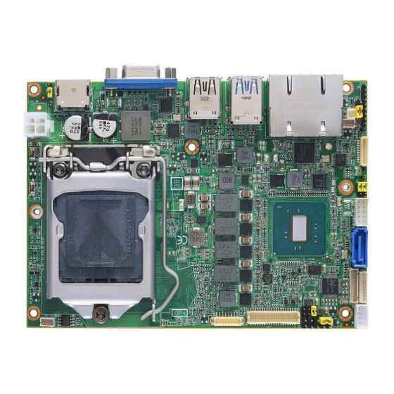
CAPA500 Intel Core Processor Family 3.5” Board Chapter 1 Introduction The CAPA500, a high performance 3.5” board, supports LGA1151 socket for 6 ® Generation Intel Core i7/ i5/ i3 processors with H110 (Q170 optional) chipsets. The board delivers outstanding system performance through high-bandwidth interfaces, multiple I/O functions for interactive applications and various embedded computing solutions. -
Page 8: Features
® CAPA500 Intel Core Processor Family 3.5” Board Features ® ® LGA1151 for 6 Generation Intel Core i7/ i5/ i3/ Celeron with TDP 35W processors H110 (Q170 optional) chipset 1 DDR4 SO-DIMM supports up to 16GB memory capacity ... -
Page 9: Utilities Supported
® CAPA500 Intel Core Processor Family 3.5” Board USB Interface Four USB ports on the rear I/O: Three for USB 3.0 and one for USB 2.0. Two USB 2.0 ports in 2x5-pin internal wafer connector. Display ... - Page 10 ® CAPA500 Intel Core Processor Family 3.5” Board This page is intentionally left blank. Introduction...
-
Page 11: Board And Pin Assignments
® CAPA500 Intel Core Processor Family 3.5” Board Chapter 2 Board and Pin Assignments Board Dimensions and Fixing Holes Top View Board and Pin Assignments... - Page 12 ® CAPA500 Intel Core Processor Family 3.5” Board Bottom View Side View Board and Pin Assignments...
-
Page 13: Board Layout
® CAPA500 Intel Core Processor Family 3.5” Board Board Layout Top View Side View Board and Pin Assignments... - Page 14 ® CAPA500 Intel Core Processor Family 3.5” Board Bottom View Board and Pin Assignments...
-
Page 15: Installing Fan
® CAPA500 Intel Core Processor Family 3.5” Board Installing Fan The processor needs specially designed heatsink and fan assembly to cool down and ensure sufficient air flow inside your system. After applying thermal grease on the processor and installing it on the socket, please place heatsink and fan assembly on top of it. -
Page 16: Jumper Settings
And remove jumper clip from 2 jumper pins to open. Below illustration shows how to set up jumper. Properly configure jumper settings on the CAPA500 to meet your application purpose. Below you can find a summary table of all jumpers and onboard default settings. -
Page 17: Lvds +3.3V/+5V/+12V Voltage Selection (Jp1)
® CAPA500 Intel Core Processor Family 3.5” Board 2.4.1 LVDS +3.3V/+5V/+12V Voltage Selection (JP1) The board supports voltage selection for flat panel displays. Use this jumper to set LVDS connector (CN4) pin 1~6 VCCM to +3.3V, +5V or +12V. To prevent hardware damage, before connecting please make sure that input voltage of flat panel is correct. -
Page 18: Connectors
® CAPA500 Intel Core Processor Family 3.5” Board Connectors Signals go to other parts of the system through connectors. Loose or improper connection might cause problems, please make sure all connectors are properly and firmly connected. Here is a summary table of connectors on the hardware. -
Page 19: Front Panel Connector (Cn1)
® CAPA500 Intel Core Processor Family 3.5” Board 2.5.1 Front Panel Connector (CN1) Signal PWR_PSON# PWRLED- PWRLED+ PWRSW- PWRSW+ HW RST- HW RST+ HDDLED- HDDLED+ Power LED Pin 4 connects anode (+) of LED and pin 3 connects cathode(-) of LED. The power LED lights up when the system is powered on. -
Page 20: Inverter Connector (Cn3)
® CAPA500 Intel Core Processor Family 3.5” Board 2.5.3 Inverter Connector (CN3) This is an 8-pin connector which is compliant with Hirose DF13-8P-1.25C for inverter. We strongly recommend you to use the matching DF13-8P-1.25C connector to avoid malfunction. Signal VBL1 (+12V level) - Page 21 ® CAPA500 Intel Core Processor Family 3.5” Board 24-bit single channel 18-bit dual channel Pin Signal Pin Signal Pin Signal Pin Signal VCCM VCCM VCCM VCCM VCCM VCCM VCCM VCCM VCCM VCCM VCCM VCCM 10 GND 10 GND 11 N.C 12 N.C...
-
Page 22: Sata Power Connector (Cn5)
® CAPA500 Intel Core Processor Family 3.5” Board 2.5.5 SATA Power Connector (CN5) The CN5 is a 1x4-pin p=2.0mm wafer for SATA power interface and fully compliant with JST B4B-PH-K-S. Signal +12V level +5V level 2.5.6 COM1 Wafer Connector (CN6) This is a 1x9-pin p=1.25mm wafer for serial port interface and fully compliant with... -
Page 23: Audio Connector (Cn7)
® CAPA500 Intel Core Processor Family 3.5” Board 2.5.7 Audio Connector (CN7) This is a 1x10-pin p=1.25mm wafer and fully compliant with Molex 53047 for audio interface. Signal Signal MIC_IN LINE_IN_L LINE_IN_R AUDIO_OUT_L AUDIO_OUT_R 2.5.8 USB 2.0 Wafer Connector (CN8) This 2x5-pin wafer is a Universal Serial Bus (USB) connector. -
Page 24: Smbus Connector (Cn10)
® CAPA500 Intel Core Processor Family 3.5” Board 2.5.10 SMBus Connector (CN10) This connector is a 1x3-pin p=2.0mm wafer and fully compliant with JST B3B-PH-K-S for SMBus interface. The SMBus (System Management Bus) is a simple bus for the purpose of lightweight communication. -
Page 25: Usb 3.0 Port (Cn14)
® CAPA500 Intel Core Processor Family 3.5” Board 2.5.13 USB 3.0 Port (CN14) This is a Universal Serial Bus (compliant with USB 3.0 (5Gb/s)) connector on the rear I/O for installing USB peripherals such as keyboard, mouse, scanner, etc. Signal... -
Page 26: Vga Connector (Cn17)
® CAPA500 Intel Core Processor Family 3.5” Board 2.5.16 VGA Connector (CN17) This is a 15-pin D-Sub connector which is commonly used for VGA display. This VGA interface configuration can be configured via software utility. Signal Signal Green Blue N.C. -
Page 27: Sata Port (Sata1)
® CAPA500 Intel Core Processor Family 3.5” Board 2.5.19 SATA Port (SATA1) This Serial Advanced Technology Attachment (Serial ATA or SATA) connector is for high speed SATA interface. It is a computer bus interface for connecting to devices such as hard disk drive. -
Page 28: Zio Expansion Connector (Scn2)
® CAPA500 Intel Core Processor Family 3.5” Board 2.5.21 ZIO Expansion Connector (SCN2) The board is equipped with SCN2 on the bottom side for connecting CPU board to a ZIO module. Signal Signal +12V +5VSB +5VSB +3.3VSB +3.3VSB RSVD RSVD... -
Page 29: Chapter 3 Hardware Description
CPU from damages. BIOS The CAPA500 uses AMI Plug and Play BIOS with a single 128Mbit SPI Flash. System Memory The CAPA500 supports one 260-pin DDR4 SO-DIMM socket for maximum memory capacity up to 16GB DDR4 SDRAMs. -
Page 30: I/O Port Address Map
® CAPA500 Intel Core Processor Family 3.5” Board I/O Port Address Map Hardware Description... -
Page 31: Interrupt Controller (Irq) Map
® CAPA500 Intel Core Processor Family 3.5” Board Interrupt Controller (IRQ) Map The interrupt controller (IRQ) mapping list is shown as follows: Hardware Description... - Page 32 ® CAPA500 Intel Core Processor Family 3.5” Board Hardware Description...
- Page 33 ® CAPA500 Intel Core Processor Family 3.5” Board Hardware Description...
- Page 34 ® CAPA500 Intel Core Processor Family 3.5” Board Hardware Description...
- Page 35 ® CAPA500 Intel Core Processor Family 3.5” Board Hardware Description...
- Page 36 ® CAPA500 Intel Core Processor Family 3.5” Board Hardware Description...
- Page 37 ® CAPA500 Intel Core Processor Family 3.5” Board Hardware Description...
- Page 38 ® CAPA500 Intel Core Processor Family 3.5” Board Hardware Description...
-
Page 39: Memory Map
® CAPA500 Intel Core Processor Family 3.5” Board Memory Map The memory mapping list is shown as follows: Hardware Description... - Page 40 ® CAPA500 Intel Core Processor Family 3.5” Board This page is intentionally left blank. Hardware Description...
-
Page 41: Ami Bios Setup Utility
® CAPA500 Intel Core Processor Family 3.5” Board Chapter 4 AMI BIOS Setup Utility The AMI UEFI BIOS provides users with a built-in setup program to modify basic system configuration. All configured parameters are stored in a flash chip to save the setup information whenever the power is turned off. - Page 42 ® CAPA500 Intel Core Processor Family 3.5” Board Hot Keys Description Left/Right The Left and Right <Arrow> keys allow you to select a setup screen. The Up and Down <Arrow> keys allow you to select a setup screen or sub ...
-
Page 43: Main Menu
® CAPA500 Intel Core Processor Family 3.5” Board Main Menu When you first enter the setup utility, you will enter the Main setup screen. You can always return to the Main setup screen by selecting the Main tab. System Time/Date can be set up as described below. -
Page 44: Advanced Menu
® CAPA500 Intel Core Processor Family 3.5” Board Advanced Menu The Advanced menu also allows users to set configuration of the CPU and other system devices. You can select any of the items in the left frame of the screen to go to the sub menus: ►... - Page 45 ® CAPA500 Intel Core Processor Family 3.5” Board ACPI Settings You can use this screen to select options for ACPI configuration, and change the value of the selected option. A description of selected item appears on the right side of the screen.
- Page 46 ® CAPA500 Intel Core Processor Family 3.5” Board CPU Configuration This screen shows the CPU Configuration. Hyper-threading Enable or disable Hyper-Threading Technology, which makes a single physical processor perform multi-tasking function as two logical ones. Intel Virtualization Technology Enable or disable Intel Virtualization Technology. When enabled, a VMM (Virtual Machine Mode) can utilize the additional hardware capabilities.
- Page 47 ® CAPA500 Intel Core Processor Family 3.5” Board SATA Configuration In the SATA Configuration menu, you can see the currently installed hardware in the SATA ports. During system boot up, the BIOS automatically detects the presence of SATA devices.
- Page 48 ® CAPA500 Intel Core Processor Family 3.5” Board PCH-FW Configuration This screen displays ME Firmware information. AMT Configuration Use this screen to configure AMT parameters. Only for Q170: Intel AMT ® Enable or disable Intel Active Management Technology BIOS Extension. The default is Enabled.
- Page 49 ® CAPA500 Intel Core Processor Family 3.5” Board USB Configuration USB Devices Display all detected USB devices. AMI BIOS Setup Utility...
- Page 50 A description of selected item appears on the right side of the screen. For items marked with “”, please press <Enter> for more options. Serial Port 1 Configuration Set parameters related to serial port 1 on CAPA500. AMI BIOS Setup Utility...
- Page 51 Serial Port 1 Configuration Serial Port Enable or disable serial port 1 on CAPA500. The optimal setting for onboard F81803 SIO address is 3F8h and for interrupt request address is IRQ4. COM Mode Use this item to set RS-232/422/485 communication mode.
- Page 52 ® CAPA500 Intel Core Processor Family 3.5” Board Hardware Monitor This screen monitors hardware health status. This screen displays the temperature of CPU and system, cooling fan speed in RPM, standby and system voltages (+3.3VSB/+5VSB and +3.3V/+5V). Smart Fan Function Enable or disable Smart Fan function.
- Page 53 ® CAPA500 Intel Core Processor Family 3.5” Board Smart Fan Mode Configuration You can use this screen to set the boundary of fan temperature and fan expect speed. Utility Configuration BIOS Flash Utility BIOS flash utility configuration. For more detailed information, please refer to Appendix D.
- Page 54 This option appears only if a ZIO module is installed. BIOS will auto-detect all supported functions and you can use it to change settings on the ZIO module. The CAPA500 supports the following ZIO expansion modules: AX93262, AX93285, AX93291 and AX93295.
- Page 55 ® CAPA500 Intel Core Processor Family 3.5” Board Onboard Device Configuration\Onboard DIO Configuration DIO Modification Enable or disable digital I/O modification. The default is Disabled. Once it is enabled, you can load manufacture default and access to the DIO status sub screen to set output or input.
- Page 56 ® CAPA500 Intel Core Processor Family 3.5” Board DIO port 1-8 AMI BIOS Setup Utility...
- Page 57 ® CAPA500 Intel Core Processor Family 3.5” Board Module Device Configuration\Module Super IO Configuration This screen is available only if a ZIO module with serial ports is connected. For items marked with “”, please press <Enter> for more options.
- Page 58 ® CAPA500 Intel Core Processor Family 3.5” Board Module Super IO Configuration You can use this screen to select options for NCT6627 Super IO Configuration, and change the value of the selected option. A description of selected item appears on the right side of the screen.
- Page 59 ® CAPA500 Intel Core Processor Family 3.5” Board Serial Port 1 Configuration Serial Port Enable or disable serial port 1 on ZIO module. The optimal setting for base I/O address is 240h and for interrupt request address is IRQ10.
- Page 60 ® CAPA500 Intel Core Processor Family 3.5” Board Serial Port 2 Configuration Serial Port Enable or disable serial port 2 on ZIO module. The optimal setting for base I/O address is 248h and for interrupt request address is IRQ3.
- Page 61 ® CAPA500 Intel Core Processor Family 3.5” Board Serial Port 3 Configuration Serial Port Enable or disable serial port 3 on ZIO module. The optimal setting for base I/O address is 250h and for interrupt request address is IRQ5.
- Page 62 ® CAPA500 Intel Core Processor Family 3.5” Board Serial Port 4 Configuration Serial Port Enable or disable serial port 4 on ZIO module. The optimal setting for base I/O address is 258h and for interrupt request address is IRQ6.
-
Page 63: Chipset Menu
® CAPA500 Intel Core Processor Family 3.5” Board Chipset Menu The Chipset menu allows users to change the advanced chipset settings. You can select any of the items in the left frame of the screen to go to the sub menus: ►... - Page 64 ® CAPA500 Intel Core Processor Family 3.5” Board System Agent (SA) Configuration This screen shows System Agent version information and provides function for specifying related parameters. Graphics Configuration Use this item to open graphics configuration sub screen. Memory Configuration Use this item to refer to information related to system memory.
- Page 65 ® CAPA500 Intel Core Processor Family 3.5” Board Primary IGFX Boot Display Select the video device which will be activated during POST (Power-On Self Test). The default is Auto. Secondary IGFX Boot Display Select the secondary display device. The default is Disabled.
- Page 66 ® CAPA500 Intel Core Processor Family 3.5” Board LVDS Panel Type Select LVDS panel resolution. AMI BIOS Setup Utility...
- Page 67 ® CAPA500 Intel Core Processor Family 3.5” Board Memory Information This screen shows the system memory information. AMI BIOS Setup Utility...
- Page 68 ® CAPA500 Intel Core Processor Family 3.5” Board PCH-IO Configuration This screen shows PCH-IO information. AMI BIOS Setup Utility...
-
Page 69: Security Menu
® CAPA500 Intel Core Processor Family 3.5” Board Security Menu The Security menu allows users to change the security settings for the system. Administrator Password This item indicates whether an administrator password has been set (installed or uninstalled). ... -
Page 70: Boot Menu
® CAPA500 Intel Core Processor Family 3.5” Board Boot Menu The Boot menu allows users to change boot options of the system. Setup Prompt Timeout Number of seconds to wait for setup activation key. 65535(0xFFFF) means indefinite waiting. ... -
Page 71: Save & Exit Menu
® CAPA500 Intel Core Processor Family 3.5” Board Save & Exit Menu The Save & Exit menu allows users to load your system configuration with optimal or fail-safe default values. Save Changes and Exit When you have completed the system configuration changes, select this option to leave Setup and return to Main Menu. - Page 72 ® CAPA500 Intel Core Processor Family 3.5” Board Discard Changes Select this option to quit Setup without making any permanent changes to the system configuration. Select Discard Changes from the Save & Exit menu and press <Enter>. Select Yes to discard changes.
-
Page 73: Appendix A Watchdog Timer
® CAPA500 Intel Core Processor Family 3.5” Board Appendix A Watchdog Timer A.1 About Watchdog Timer Software stability is major issue in most application. Some embedded systems are not watched by operator for 24 hours. It is usually too slow to wait for someone to reboot when computer hangs. -
Page 74: A.3 Sample Program
® CAPA500 Intel Core Processor Family 3.5” Board A.3 Sample Program Assembly sample code : ;Enable WDT: dx,2Eh al,87 ;Un-lock super I/O dx,al dx,al ;Select Logic device: dx,2Eh al,07h dx,al dx,2Fh al,07h dx,al ;Enable WDT base address: dx,2Eh al,30h dx,al... - Page 75 ® CAPA500 Intel Core Processor Family 3.5” Board If N=79h, the time base is set to minute. M = time value 00: Time-out disable 01: Time-out occurs after 1 minute 02: Time-out occurs after 2 minutes 03: Time-out occurs after 3 minutes...
- Page 76 ® CAPA500 Intel Core Processor Family 3.5” Board This page is intentionally left blank. Watchdog Timer...
-
Page 77: Appendix B Digital I/O
® CAPA500 Intel Core Processor Family 3.5” Board Appendix B Digital I/O B.1 About Digital I/O The digital I/O on CPU board has 8 bits. Each bit can be set to function as input or output by software programming. In default, all pins are pulled high with +5V level (according to main power). - Page 78 ® CAPA500 Intel Core Processor Family 3.5” Board Register 0: Input port register. This register is a read-only port. It reflects the incoming logic levels of the pins, regardless of whether the pin is defined as an input or an output by Register 3. Writes to this register have no effect.
- Page 79 ® CAPA500 Intel Core Processor Family 3.5” Board Register 3: Configuration register. This register configures the directions of the I/O pins. If a bit in this register is set, the corresponding port pin is enabled as an input with high-impedance output driver. If a bit in this register is cleared, the corresponding port pin is enabled as an output.
- Page 80 ® CAPA500 Intel Core Processor Family 3.5” Board This page is intentionally left blank. Digital I/O...
-
Page 81: Appendix C Iamt Settings
® CAPA500 Intel Core Processor Family 3.5” Board Appendix C iAMT Settings ® ® The Intel Active Management Technology (Intel iAMT) has decreased a major barrier to IT efficiency that uses built-in platform capabilities and popular third-party management and security applications to allow IT a better discovering, healing, and protection their networked computing assets. - Page 82 ® CAPA500 Intel Core Processor Family 3.5” Board You will be asked to change the password before setting ME. You must confirm your new password while revising. The new password must contain: (example: !!11qqQQ) (default value). Eight characters ...
-
Page 83: Iamt Settings
® CAPA500 Intel Core Processor Family 3.5” Board iAMT Settings ® Select Intel Standard ManageabilityConfiguration and press <Enter>. Select Network Setup to configure iAMT. iAMT Settings... - Page 84 ® CAPA500 Intel Core Processor Family 3.5” Board Select TCP/IP to get into Network interface and set it to Enabled. Get into DHCP Mode and set it to Disabled. iAMT Settings...
- Page 85 ® CAPA500 Intel Core Processor Family 3.5” Board If DHCP Mode is disabled, set the following settings: IP address Subnet mask ® Go back to Intel iAMT Configuration, then select Activate Network Access and press <Enter>. Exit from MEBx after completing the iAMT settings.
-
Page 86: Iamt Web Console
® CAPA500 Intel Core Processor Family 3.5” Board iAMT Web Console From a web browser, please type http://(IP ADDRESS):16992, which connects to iAMT Web. Example: http://10.1.40.214:16992 To log on, you will be required to type in username and password for access to the Web. - Page 87 ® CAPA500 Intel Core Processor Family 3.5” Board Enter the iAMT Web. Click Remote Control, and select commands on the right side. When you have finished using the iAMT Web console, close the Web browser. iAMT Settings...
- Page 88 ® CAPA500 Intel Core Processor Family 3.5” Board This page is intentionally left blank. iAMT Settings...
-
Page 89: Appendix Dbios Flash Utility
Please read and follow the instructions below carefully. In your USB flash drive, create a new folder and name it “Axiomtek”, see figure below. Copy BIOS ROM file (e.g. CAPA500X.005) to “Axiomtek” folder. - Page 90 Select the USB drive containing BIOS ROM file you want to update using the <> or <> key. Then press <Enter> to get into “Axiomtek” folder. Now you can see the BIOS ROM file on the screen, press <Enter> to select.
- Page 91 ® CAPA500 Intel Core Processor Family 3.5” Board Please wait while BIOS completes the entire flash update process: erase data, write new data and verify data. 10. When you see the following figure, press <Enter> to finish the update process. After that the system will shut down and restart immediately.
Need help?
Do you have a question about the CAPA500 and is the answer not in the manual?
Questions and answers