AXIOMTEK CAPA318 User Manual
Intel pentium processor n4200
and celeron processor n3350
3.5 inch board
Hide thumbs
Also See for CAPA318:
- Quick installation manual (2 pages) ,
- Quick installation manual (2 pages)

Related Manuals for AXIOMTEK CAPA318


Summary of Contents for AXIOMTEK CAPA318
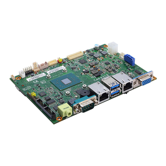
- Page 1 CAPA318 ® ® Intel Pentium Processor N4200 ® and Celeron Processor N3350 3.5” Board User’s Manual...
-
Page 2: Disclaimers
Axiomtek does not make any commitment to update the information in this manual. Axiomtek reserves the right to change or revise this document and/or product at any time without notice. No part of this document may be reproduced, stored in a retrieval system, or transmitted, in any form or by any means, electronic, mechanical, photocopying, recording, or otherwise, without the prior written permission of Axiomtek Co., Ltd. -
Page 3: Esd Precautions
It discharges static electricity from your body. Wear a wrist-grounding strap, available from most electronic component stores, when handling boards and components. Trademarks Acknowledgments Axiomtek is a trademark of Axiomtek Co., Ltd. ® ® Intel and Celeron are trademarks of Intel Corporation. -
Page 4: Table Of Contents
Table of Contents Disclaimers ..................... ii ESD Precautions ................... iii Chapter 1 Introduction ..........1 Features ....................2 Specifications ..................2 Utilities Supported ................3 Chapter 2 Board and Pin Assignments ....5 Board Dimensions and Fixing Holes ..........5 Board Layout .................. - Page 5 Microprocessors ................23 BIOS ....................23 System Memory ................. 23 I/O Port Address Map ................ 24 Interrupt Controller (IRQ) Map ............25 Memory Map ..................31 Chapter 4 AMI BIOS Setup Utility ......33 Starting ....................33 Navigation Keys ................33 Main Menu ..................
- Page 6 This page is intentionally left blank.
-
Page 7: Chapter 1 Introduction
I/O functions for interactive applications and various embedded computing solutions. The CAPA318 comes with one 204-pin unbuffered SO-DIMM socket for single channel DDR3L 1600MHz memory, maximum memory capacity up to 8GB. There are two Gigabit/Fast Ethernet ports, one SATA port with transfer rate up to 6Gb/s, two USB 3.0 and two USB 2.0... -
Page 8: Features
CAPA318 3.5” Board Features ® ® ® Intel Pentium quad core N4200 (1.1GHz) and Celeron dual core N3350 (1.1GHz) 1 DDR3L SO-DIMM supports up to 8GB memory capacity 2 USB 3.0 ports and 2 USB 2.0 ports ... -
Page 9: Utilities Supported
CAPA318 3.5” Board Watchdog Timer Timeout value range is 1~65535 seconds. Ethernet ® Two RJ-45 LAN ports: Intel i211AT supports 1000/100/10Mbps Gigabit/Fast Ethernet with Wake-on-LAN and PXE Boot ROM. Audio HD audio compliant with Realtek ALC662. - Page 10 CAPA318 3.5” Board This page is intentionally left blank. Introduction...
-
Page 11: Board And Pin Assignments
CAPA318 3.5” Board Chapter 2 Board and Pin Assignments Board Dimensions and Fixing Holes Top View Board and Pin Assignments... - Page 12 CAPA318 3.5” Board Bottom View Side View Board and Pin Assignments...
-
Page 13: Board Layout
CAPA318 3.5” Board Board Layout Top View Side View Board and Pin Assignments... - Page 14 CAPA318 3.5” Board Bottom View Board and Pin Assignments...
-
Page 15: Jumper And Switch Settings
And remove jumper clip from 2 jumper pins to open. Below illustration shows how to set up jumper. Properly configure jumper and switch settings on the CAPA318 to meet your application purpose. Below you can find a summary table of jumpers, switch and onboard default settings. -
Page 16: Lvds +3.3V/+5V/+12V Voltage Selection (Jp1)
CAPA318 3.5” Board 2.3.1 LVDS +3.3V/+5V/+12V Voltage Selection (JP1) This is a 2x3-pin (pitch=2.0mm) jumper. The board supports voltage selection for flat panel displays. Use these jumpers to set LVDS connector (CN5) pin 1~6 VCCM to +3.3V, +5V or +12V. To prevent hardware damage, before connecting please make sure that the input voltage of flat panel is correct. -
Page 17: Connectors
CAPA318 3.5” Board Connectors Signals go to other parts of the system through connectors. Loose or improper connection might cause problems, please make sure all connectors are properly and firmly connected. Here is a summary table of connectors on the hardware. -
Page 18: Usb 2.0 Wafer Connector (Cn1)
CAPA318 3.5” Board 2.4.1 USB 2.0 Wafer Connector (CN1) This 2x5-pin (pitch=2mm) wafer which is compliant with Hirose DF11-xdp-2dsa and a Universal Serial Bus (USB) connector for installing versatile USB 2.0 compliant interface peripherals. Signal Signal USB VCC USB VCC... -
Page 19: Inverter Connector (Cn3)
CAPA318 3.5” Board 2.4.3 Inverter Connector (CN3) This is a DF13-8P-1.25C 8-pin (pitch=1.25mm) connector for inverter. We strongly recommend you to use the matching DF13-8P-1.25C connector to avoid malfunction. Signal VBL1 (+12V level) VBL1 (+12V level) VBL2 (+5V level) VBL_ENABLE VBL Brightness Control 2.4.4... -
Page 20: Lvds Connector (Cn5)
CAPA318 3.5” Board 2.4.5 LVDS Connector (CN5) This board has a 2x20-pin (pitch=1mm) connector for LVDS LCD interface. It is strongly recommended to use the matching JST SHDR-40VS-B connector for LVDS interface. Pin 1~6 VCCM can be set to +3.3V, +5V or +12V by setting JP1 (see section 2.3.1). - Page 21 CAPA318 3.5” Board 24-bit single channel 18-bit dual channel Pin Signal Pin Signal Pin Signal Pin Signal VCCM VCCM VCCM VCCM VCCM VCCM VCCM VCCM VCCM VCCM VCCM VCCM 10 GND 10 GND 11 N.C 12 N.C 11 N.C 12 Channel B D0- 13 N.C...
-
Page 22: Smbus Connector (Cn6)
CAPA318 3.5” Board 2.4.6 SMBus Connector (CN6) This connector is a 3-pin (pitch=2.0mm) wafer connector, which is compliant with JST B3B-PH-K-S, for SMBus interface. The SMBus (System Management Bus) is a simple bus for the purpose of lightweight communication. Signal... -
Page 23: Audio Connector (Cn13)
CAPA318 3.5” Board 2.4.10 Audio Connector (CN13) This is a 2x5-pin connector for audio interface. Signal Signal MIC_IN LINE_IN_L LINE_IN_R AUDIO_OUT_L AUDIO_OUT_R 2.4.11 Audio Jack (CN14) This is audio jack with HD audio support. Install audio driver, and then attach audio device to CN14. -
Page 24: Sata Connector (Sata1)
CAPA318 3.5” Board 2.4.14 SATA Connector (SATA1) This Serial Advanced Technology Attachment (Serial ATA or SATA) connector is for high-speed SATA interface. It is a computer bus interface for connecting to devices such as hard disk drive. Signal SATA_TXP0 SATA_TXN0... -
Page 25: Atx Power Connector (Atx1)
CAPA318 3.5” Board 2.4.17 ATX Power Connector (ATX1) Steady and sufficient power can be supplied to all components on the board by connecting the power connector. Please make sure all components and devices are properly installed before connecting the power connector. -
Page 26: Full-Size Pci-Express Mini Card And Msata Connector (Scn1)
CAPA318 3.5” Board 2.4.19 Full-size PCI-Express Mini Card and mSATA Connector (SCN1) This is a full-size PCI-Express Mini Card connector on the bottom side complying with PCI-Express Mini Card Spec. V1.2. It supports either PCI-Express, USB 2.0 or SATA (mSATA). Since the default setting is mSATA, if PCI-Express Mini Card is needed to insert, please refer to section 4.4 to change the setting. -
Page 27: Full-Size Pci-Express Mini Card Connector (Scn2)
CAPA318 3.5” Board 2.4.20 Full-size PCI-Express Mini Card Connector (SCN2) This is a full-size PCI-Express Mini Card connector on the bottom side supporting PCI-Express x1 or USB 2.0. It also complies with PCI-Express Mini Card Spec. V1.2. Signal Signal WAKE# +3.3VSB... - Page 28 CAPA318 3.5” Board This page is intentionally left blank. Board and Pin Assignments...
-
Page 29: Chapter 3 Hardware Description
Make sure all correct settings are arranged for your installed microprocessor to prevent the CPU from damages. BIOS The CAPA318 uses AMI Plug and Play BIOS with a single 64Mbit SPI Flash. System Memory The CAPA318 supports one 204-pin DDR3L SO-DIMM socket for maximum memory capacity up to 8GB DDR3L SDRAMs. -
Page 30: I/O Port Address Map
CAPA318 3.5” Board I/O Port Address Map Hardware Description... -
Page 31: Interrupt Controller (Irq) Map
CAPA318 3.5” Board Interrupt Controller (IRQ) Map The interrupt controller (IRQ) mapping list is shown as follows: Hardware Description... - Page 32 CAPA318 3.5” Board Hardware Description...
- Page 33 CAPA318 3.5” Board Hardware Description...
- Page 34 CAPA318 3.5” Board Hardware Description...
- Page 35 CAPA318 3.5” Board Hardware Description...
- Page 36 CAPA318 3.5” Board Hardware Description...
-
Page 37: Memory Map
CAPA318 3.5” Board Memory Map The memory mapping list is shown as follows: Hardware Description... - Page 38 CAPA318 3.5” Board This page is intentionally left blank. Hardware Description...
-
Page 39: Ami Bios Setup Utility
CAPA318 3.5” Board Chapter 4 AMI BIOS Setup Utility The AMI UEFI BIOS provides users with a built-in setup program to modify basic system configuration. All configured parameters are stored in a flash chip to save the setup information whenever the power is turned off. This chapter provides users with detailed description about how to set up basic system configuration through the AMI BIOS setup utility. - Page 40 CAPA318 3.5” Board Hot Keys Description Left/Right The Left and Right <Arrow> keys allow you to select a setup screen. The Up and Down <Arrow> keys allow you to select a setup screen or Up/Down sub-screen. The Plus and Minus <Arrow> keys allow you to change the field value of a +...
-
Page 41: Main Menu
CAPA318 3.5” Board Main Menu When you first enter the setup utility, you will enter the Main setup screen. You can always return to the Main setup screen by selecting the Main tab. System Time/Date can be set up as described below. -
Page 42: Advanced Menu
CAPA318 3.5” Board Advanced Menu The Advanced menu also allows users to set configuration of the CPU and other system devices. You can select any of the items in the left frame of the screen to go to the sub menus: ►... - Page 43 CAPA318 3.5” Board Hardware Monitor This screen monitors hardware health status. This screen displays the temperature of system and CPU, fan speed in RPM and system voltages (VBAT, +3.3V, +3.3V_SBY and +5V). AMI BIOS Setup Utility...
- Page 44 CAPA318 3.5” Board ACPI Settings ACPI Sleep State Select the ACPI (Advanced Configuration and Power Interface) sleep state. Configuration options are Suspend Disabled and S3 (Suspend to RAM). The S3 (Suspend to RAM) option selects ACPI sleep state the system will enter when suspend button is pressed.
- Page 45 CAPA318 3.5” Board CPU Configuration This screen shows the CPU Configuration. Intel Virtualization Technology Enable or disable Intel Virtualization Technology. When enabled, a VMM (Virtual Machine Mode) can utilize the additional hardware capabilities. It allows a platform to run multiple operating systems and applications independently, hence enabling a computer system to work as several virtual systems.
- Page 46 CAPA318 3.5” Board SATA Configuration In the SATA Configuration menu, you can see the currently installed hardware in the SATA ports. During system boot up, the BIOS automatically detects the presence of SATA devices. Chipset SATA Enable or disable Chipset SATA Controller. The default is Enable.
- Page 47 CAPA318 3.5” Board PCIE/mSATA Choose PCIE or mSATA for PCI-Express Mini Card. The default is mSATA. If PCI-Express Mini Card is needed to insert to SCN1 (see section 2.4.19), please change setting to PCIE. AMI BIOS Setup Utility...
- Page 48 CAPA318 3.5” Board USB Configuration USB Devices Display all detected USB devices. AMI BIOS Setup Utility...
- Page 49 CAPA318 3.5” Board Serial Port Configuration You can use this screen to select options for the Serial Port Configuration, and change the value of the selected option. A description of the selected item appears on the right side of the screen.
- Page 50 CAPA318 3.5” Board Serial Port 1 (UART1) Serial Port Enable or disable serial port 1. The optimal setting for base I/O address is 248h and for interrupt request address is IRQ10. AMI BIOS Setup Utility...
- Page 51 CAPA318 3.5” Board Serial Port 2 (UART2) Serial Port Enable or disable serial port 2. The optimal setting for base I/O address is 258h and for interrupt request address is IRQ11. Utility Configuration BIOS Flash Utility BIOS flash utility configuration. For more detailed information, please refer to Appendix C.
- Page 52 CAPA318 3.5” Board Device Configuration A description of selected item appears on the right side of the screen. For items marked with “”, please press <Enter> for more options. Onboard Device Configuration Use this option to configure onboard device (e.g., DIO setting).
- Page 53 CAPA318 3.5” Board Onboard Device Configuration\Onboard DIO Configuration A description of selected item appears on the right side of the screen. For items marked with “”, please press <Enter> for more options. AMI BIOS Setup Utility...
- Page 54 CAPA318 3.5” Board DIO Modification Enable or disable digital I/O modification. The default is Disabled. Once it is enabled, you can load manufacture default and access to the DIO status sub screen to set output or input, see image below.
- Page 55 CAPA318 3.5” Board Load Manufacture Default Use this option to load default settings. DIO port 1-8 Select this option to open DIO status sub screen to set output or input for each port. AMI BIOS Setup Utility...
- Page 56 CAPA318 3.5” Board DIO Status DIO Status sub screen. AMI BIOS Setup Utility...
-
Page 57: Chipset Menu
CAPA318 3.5” Board Chipset Menu The Chipset menu allows users to change the advanced chipset settings. You can select any of the items in the left frame of the screen to go to the sub menus: ► North Bridge ►... - Page 58 CAPA318 3.5” Board North Bridge This screen allows users to configure parameters of North Bridge chipset. LCD Control This item allows you to select LCD panel control options. Please press <Enter> to go to the sub menus. Memory Information Display system memory information.
- Page 59 CAPA318 3.5” Board LVDS Panel Type Select LVDS panel resolution for the display device by selecting the appropriate setup item. AMI BIOS Setup Utility...
- Page 60 CAPA318 3.5” Board GMCH BLC Control Use this item for backlight control setting. AMI BIOS Setup Utility...
- Page 61 CAPA318 3.5” Board South Bridge This screen shows the information of South Bridge chipset. AMI BIOS Setup Utility...
-
Page 62: Security Menu
CAPA318 3.5” Board Security Menu The Security menu allows users to change the security settings for the system. Administrator Password This item indicates whether an administrator password has been set (installed or uninstalled). User Password This item indicates whether an user password has been set (installed or uninstalled). -
Page 63: Boot Menu
CAPA318 3.5” Board Boot Menu The Boot menu allows users to change boot options of the system. Setup Prompt Timeout Number of seconds to wait for setup activation key. 65535(0xFFFF) means indefinite waiting. Bootup NumLock State Use this item to select the power-on state for the keyboard NumLock. - Page 64 CAPA318 3.5” Board Quiet Boot Select to display either POST output messages or a splash screen during boot-up. Launch UEFI PXE OpROM Control the execution of UEFI PXE OpROM. Boot Option Priorities These are settings for boot priority. Specify the boot device priority sequence from the available devices.
- Page 65 CAPA318 3.5” Board Boot Mode Use this item for boot mode settings. UEFI Boot: Select support to boot any UEFI-capable OS. Legacy Boot: Select support to boot non UEFI-capable OS that expects a legacy BIOS interface. AMI BIOS Setup Utility...
- Page 66 CAPA318 3.5” Board Note that the Primary IGFX Boot Display option appears only if Legacy Mode is selected, see image below. Primary IGFX Boot Display Select the video device which will be activated during POST (Power-On Self Test). The following image shows the option list when LVDS Panel Device is disabled.
-
Page 67: Save & Exit Menu
CAPA318 3.5” Board Save & Exit Menu The Save & Exit menu allows users to load your system configuration with optimal or fail-safe default values. Save Changes and Exit When you have completed the system configuration changes, select this option to leave Setup and return to Main Menu. - Page 68 CAPA318 3.5” Board Discard Changes Select this option to quit Setup without making any permanent changes to the system configuration. Select Discard Changes from the Save & Exit menu and press <Enter>. Select Yes to discard changes. Restore Defaults It automatically sets all Setup options to a complete set of default settings when you select this option.
-
Page 69: Appendix A Watchdog Timer
CAPA318 3.5” Board Appendix A Watchdog Timer A.1 About Watchdog Timer After the system stops working for a while, it can be auto-reset by the watchdog timer. The integrated watchdog timer can be set up in the system reset mode by program. - Page 70 CAPA318 3.5” Board This page is intentionally left blank. Watchdog Timer...
-
Page 71: Appendix B Digital I/O
CAPA318 3.5” Board Appendix B Digital I/O B.1 About Digital I/O The onboard GPIO or digital I/O has 8 bits (DIO1~8). Each bit can be set to function as input or output by software programming. In default, all pins are pulled high with +5V level (according to main power). - Page 72 CAPA318 3.5” Board This page is intentionally left blank. Digital I/O...
-
Page 73: Appendix Cbios Flash Utility
Please read and follow the instructions below carefully. In your USB flash drive, create a new folder and name it “Axiomtek”, see figure below. Copy BIOS ROM file (e.g. CAPA318.005) to “Axiomtek” folder. - Page 74 Select the USB drive containing BIOS ROM file you want to update using the <> or <> key. Then press <Enter> to get into “Axiomtek” folder. Now you can see the BIOS ROM file on the screen, press <Enter> to select.
- Page 75 CAPA318 3.5” Board Please wait while BIOS completes the entire flash update process: erase data, write new data and verify data. 10. When you see the following figure, press <Enter> to finish the update process. After that the system will shut down and restart immediately.
Need help?
Do you have a question about the CAPA318 and is the answer not in the manual?
Questions and answers