Advertisement
Quick Start
CN12
The basic procedures required to power on CAPA313:
(1). Require power at minimum 12V/1.07A or 24V/0.63A. Check to
ensure that power supply is OFF before connecting to
CAPA313 and that all necessary peripheral devices are
plugged properly.
(2). Make sure all of the jumpers and switch are at default settings;
especially SSW 1 (1-2 close).
(3). Firmly install DDR3L memory module into connector SDIMM1
until fully seated.
(4). Firmly insert power to ATX1.
(5). Install a momentary on/off button/switch onto CN12, pin 5 and
6.
(6). Turn on the power supply.
(7). Press the on/off button/switch to power on CAPA313.
4
9418E313000E
©
Copyright 2018 Axiomtek Co., Ltd.
Version A1 June 2018
Printed in Taiwan
CAPA313 Series Quick Installation Guide
Checklist
CPU board x1
Product information CD x1
Quick installation guide x1
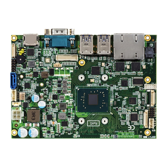
Connectors
Connector
Description
CN1
SMBus Connector
CN2
Audio Connector
CN4
Digital I/O Connector
2
CN5
I
C Connector
CN6
COM2 Wafer Connector
CN7 (Optional)
COM1 Wafer Connector
CN8
Fan Connector
CN9
SATA Power Connector
CN10
USB 2.0 Wafer Port 5 and 6
CN11
SATA Connector
CN12
Front Panel Connector
CN13
LVDS Connector
CN14
Inverter Connector
CN16
Ethernet Port 1 and 2
CN17~CN18
USB 3.0 Port 0~3
CN20
COM1 D-Sub Connector
CN21
HDMI Connector
CN22 (Optional)
VGA Connector
ATX1
ATX Power Connector
SCN1, SCN3
Full-size PCI-Express Mini Card Connectors
SCN2
ZIO Expansion Connector
SDIMM1
DDR3L SO-DIMM Connector
9418E313000E
©
Copyright 2018 Axiomtek Co., Ltd.
Version A1 June 2018
Printed in Taiwan
1
Advertisement
Table of Contents

Related Manuals for AXIOMTEK CAPA313 Series


Summary of Contents for AXIOMTEK CAPA313 Series
- Page 1 CAPA313 Series Quick Installation Guide Quick Start CN12 Checklist CPU board x1 Product information CD x1 Quick installation guide x1 Connectors Connector Description SMBus Connector Audio Connector Digital I/O Connector C Connector The basic procedures required to power on CAPA313: COM2 Wafer Connector (1).
- Page 2 NOT apply power to the board if there is any damaged component. Board Layout Bottom View Side View Note: Please refer to the CAPA313 series product information CD for the complete user’s manual, drivers and utilities. User’s manual and related Top View documents are in Acrobat PDF format.
Need help?
Do you have a question about the CAPA313 Series and is the answer not in the manual?
Questions and answers