AXIOMTEK CAPA841 User Manual
Hide thumbs
Also See for CAPA841:
- Quick installation manual (2 pages) ,
- Quick installation manual (2 pages)

Related Manuals for AXIOMTEK CAPA841


Summary of Contents for AXIOMTEK CAPA841
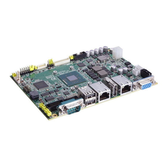
- Page 1 CAPA841/842 ® Intel Atom E3845/E3827 ® ® Intel Celeron J1900/N2807 Processors Capa Board User’s Manual...
-
Page 2: Disclaimers
Axiomtek does not make any commitment to update the information in this manual. Axiomtek reserves the right to change or revise this document and/or product at any time without notice. No part of this document may be reproduced, stored in a retrieval system, or transmitted, in any form or by any means, electronic, mechanical, photocopying, recording, or otherwise, without the prior written permission of Axiomtek Co., Ltd. -
Page 3: Esd Precautions
Wear a wrist-grounding strap, available from most electronic component stores, when handling boards and components. Trademarks Acknowledgments Axiomtek is a trademark of Axiomtek Co., Ltd. ® Windows is a trademark of Microsoft Corporation. AMI is a trademark of American Megatrend Inc. -
Page 4: Table Of Contents
Table of Contents Disclaimers ..................... ii ESD Precautions ................... iii Chapter 1 Introduction ..........1 Features ....................2 Specifications ..................2 Utilities Supported ................3 Chapter 2 Board and Pin Assignments ....5 Board Dimensions and Fixing Holes ..........5 Board Layout .................. - Page 5 2.4.18 COM1 Connector (COM1) ................ 22 2.4.19 COM2 Connector (COM2) ................ 23 2.4.20 CMOS Battery Connector (BAT1) ............. 23 2.4.21 Half-size PCI-Express Mini Card Connector (SCN1) ........ 24 2.4.22 Full-size PCI-Express Mini Card Connector (SCN2) ........ 25 2.4.23 SIM Card Socket (SCN3) ................26 Chapter 3 Hardware Description ......
- Page 6 Digital I/O Programming ................82...
-
Page 7: Chapter 1 Introduction
I/O functions for interactive applications and various embedded computing solutions. The CAPA841/CAPA842 comes with one 204-pin unbuffered SO-DIMM socket for single channel DDR3L 1333/1066MHz memory, maximum memory capacity up to 8GB. There are two Gigabit/Fast Ethernet ports, one SATA port with transfer rate up to 3Gb/s, four USB 2.0... -
Page 8: Features
- Intel Celeron dual core N2807 1.58GHz. Thermal Solution Passive. Operating Temperature CAPA841: -40°C~80°C or -20 C~80 CAPA842: -20 C~-70 BIOS American Megatrends Inc. UEFI (Unified Extensible Firmware Interface) BIOS. 16Mbit SPI Flash, DMI, Plug and Play. -
Page 9: Utilities Supported
CAPA841/842 Capa Board Trusted Platform Module (TPM) Controller: ST ST33TPM12LPC via LPC bus interface. Complies with TPM1.2 main and PC client specification. Watchdog Timer 1~255 seconds or minutes; up to 255 levels. Ethernet ®... - Page 10 CAPA841/842 Capa Board This page is intentionally left blank. Introduction...
-
Page 11: Board And Pin Assignments
CAPA841/842 Capa Board Chapter 2 Board and Pin Assignments Board Dimensions and Fixing Holes Top View Board and Pin Assignments... - Page 12 CAPA841/842 Capa Board Bottom View Side View Board and Pin Assignments...
-
Page 13: Board Layout
CAPA841/842 Capa Board Board Layout Top View Side View Board and Pin Assignments... - Page 14 CAPA841/842 Capa Board Bottom View Board and Pin Assignments...
-
Page 15: Jumper Settings
And remove jumper clip from 2 jumper pins to open. Below illustration shows how to set up jumper. Properly configure jumper settings on the CAPA841/842 to meet your application purpose. Below you can find a summary table of all jumpers and onboard default settings. -
Page 16: Lvds Voltage Selection (Jp1 And Jp6)
CAPA841/842 Capa Board 2.3.1 LVDS Voltage Selection (JP1 and JP6) The board supports voltage selection for flat panel displays. Use these jumpers to set LVDS connector (CN3) pin 1~6 VCCM to +3.3V, +5V or +12V. To prevent hardware damage, before connecting please make sure that input voltage of flat panel is correct. -
Page 17: Com4 Data/Power Selection (Jp7)
CAPA841/842 Capa Board 2.3.5 COM4 Data/Power Selection (JP7) The COM4 port has +5V level power capability on DCD and +12V level on RI by setting this jumper. Function Setting Power: Set CN11 pin 11 to +5V level 1-3 close Data: Set CN11 pin 11 to DCD (Default) -
Page 18: Com1 Data/Power Selection (Jp12)
CAPA841/842 Capa Board 2.3.9 COM1 Data/Power Selection (JP12) The COM1 port has +5V level power capability on DCD and +12V level on RI by setting this jumper. When this port is set to +5V or +12V level, please make sure its communication mode is RS-232. -
Page 19: Connectors
CAPA841/842 Capa Board Connectors Signals go to other parts of the system through connectors. Loose or improper connection might cause problems, please make sure all connectors are properly and firmly connected. Here is a summary table of connectors on the hardware. -
Page 20: Front Panel Connector (Cn1)
CAPA841/842 Capa Board 2.4.1 Front Panel Connector (CN1) Signal PWRLED+ EXT SPK- N.C. Buzzer PWRLED- N.C. N.C. EXT SPK+ PWRSW- PWRSW+ HW RST- HW RST+ HDDLED- HDDLED+ Power LED Pin 1 connects anode(+) of LED and pin 5 connects cathode(-) of LED. The power LED lights up when the system is powered on. -
Page 21: Inverter Connector (Cn2)
CAPA841/842 Capa Board 2.4.2 Inverter Connector (CN2) This is a DF13-8S-1.25C 8-pin connector for inverter. We strongly recommend you to use the matching DF13-8S-1.25C connector to avoid malfunction. Signal VBL1 (+12V level) VBL1 (+12V level) VBL2 (+5V level) VBL_ENABLE VBL Brightness Control 2.4.3... - Page 22 CAPA841/842 Capa Board 24-bit single channel 18-bit dual channel Pin Signal Pin Signal Pin Signal Pin Signal 1 VCCM VCCM VCCM VCCM VCCM VCCM VCCM VCCM VCCM VCCM VCCM VCCM N.C. N.C. N.C. N.C. 10 GND 10 GND 11 N.C.
-
Page 23: Audio Connector (Cn4)
CAPA841/842 Capa Board 2.4.4 Audio Connector (CN4) Pin 7 and pin 9 of connector CN4 can be set to different audio source by setting JP2 (see section 2.3.2). Signal Signal MIC_IN LINE_IN_L LINE_IN_R AUDIO_OUT_L AUDIO_OUT_R 2.4.5 Digital I/O Port Connector (CN5) The board is equipped with an 8-channel (3 inputs and 5 outputs) digital I/O connector that meets requirements for a system customary automation control. -
Page 24: Usb Wafer Connector (Cn9)
CAPA841/842 Capa Board 2.4.8 USB Wafer Connector (CN9) This 2x5 pin wafer is a Universal Serial Bus (USB) connector for installing versatile USB 2.0 compliant interface peripherals. The CN9 carries USB port 2 and 3. Signal Signal USB VCC (+5V... -
Page 25: Com3 And Com4 Connector (Cn11)
CAPA841/842 Capa Board 2.4.10 COM3 and COM4 Connector (CN11) Both COM3 and COM4 ports have +5V level power capability on DCD and 12V level on RI by setting JP8 and JP7, respectively (see section 2.3.6 and 2.3.5). The pin assignments are listed in table below. -
Page 26: Power Connector (Atx1)
CAPA841/842 Capa Board 2.4.13 Power Connector (ATX1) Steady and sufficient power can be supplied to all components on the board by connecting the power connector. Please make sure all components and devices are properly installed before connecting the power connector. -
Page 27: Usb Port (Usb1)
CAPA841/842 Capa Board 2.4.15 USB Port (USB1) The USB1 is a Universal Serial Bus (compliant with USB 2.0 (480Mbps)) connector on the rear I/O. It is commonly used for installing USB peripherals such as keyboard, mouse, scanner, etc. Signal Signal... -
Page 28: Ethernet Ports (Lan1 And Lan2)
CAPA841/842 Capa Board 2.4.17 Ethernet Ports (LAN1 and LAN2) The board has two RJ-45 connectors: LAN1 and LAN2. Ethernet connection can be established by plugging one end of the ethernet cable into this RJ-45 connector and the other end (phone jack) to a 1000/100/10-Base-T hub. -
Page 29: Com2 Connector (Com2)
CAPA841/842 Capa Board 2.4.19 COM2 Connector (COM2) This connector is equipped with +5V level power capability on DCD and +12V level on RI by setting JP11 (see section 2.3.8). The pin assignments of RS-232/RS-422/RS-485 are listed in table below. If you need COM2 port to support RS-422 or RS-485, please refer to BIOS setting in section 4.4. -
Page 30: Half-Size Pci-Express Mini Card Connector (Scn1)
CAPA841/842 Capa Board 2.4.21 Half-size PCI-Express Mini Card Connector (SCN1) The SCN1 is a half-size PCI-Express Mini Card connector. It supports the PCI-Express Mini Cards which are applied to either PCI-Express x1 or USB. It complies with PCI-Express Mini Card Spec. V1.2. -
Page 31: Full-Size Pci-Express Mini Card Connector (Scn2)
CAPA841/842 Capa Board 2.4.22 Full-size PCI-Express Mini Card Connector (SCN2) This is a PCI-Express Mini Card connector on the bottom side applying to either PCI-Express or USB 2.0 or SATA (mSATA). It complies with PCI-Express Mini Card Spec. V1.2. It can also support mSATA cards. Please refer to BIOS setting in section 4.4 to... -
Page 32: Sim Card Socket (Scn3)
CAPA841/842 Capa Board 2.4.23 SIM Card Socket (SCN3) This board has SCN3 socket on the bottom side for inserting SIM Card. In order to work properly, the SIM Card must be used together with 3G module which is inserted to SCN1 or SCN2. -
Page 33: Chapter 3 Hardware Description
Make sure all correct settings are arranged for your installed microprocessor to prevent the CPU from damages. BIOS The CAPA841/842 uses AMI Plug and Play BIOS with a single 16Mbit SPI Flash. System Memory The CAPA841/842 supports one 204-pin DDR3L SO-DIMM socket for a maximum memory of 8GB DDR3L SDRAMs. -
Page 34: I/O Port Address Map
CAPA841/842 Capa Board I/O Port Address Map Total 1KB port addresses are available for assigning to other devices via I/O expansion cards. Hardware Description... - Page 35 CAPA841/842 Capa Board Hardware Description...
-
Page 36: Interrupt Controller (Irq) Map
CAPA841/842 Capa Board Interrupt Controller (IRQ) Map The interrupt controller (IRQ) mapping list is shown as follows: Hardware Description... - Page 37 CAPA841/842 Capa Board Hardware Description...
- Page 38 CAPA841/842 Capa Board Hardware Description...
- Page 39 CAPA841/842 Capa Board Hardware Description...
- Page 40 CAPA841/842 Capa Board Hardware Description...
- Page 41 CAPA841/842 Capa Board Hardware Description...
-
Page 42: Memory Map
CAPA841/842 Capa Board Memory Map The memory mapping list is shown as follows: Hardware Description... -
Page 43: Ami Bios Setup Utility
CAPA841/842 Capa Board Chapter 4 AMI BIOS Setup Utility The AMI UEFI BIOS provides users with a built-in setup program to modify basic system configuration. All configured parameters are stored in a flash chip to save the setup information whenever the power is turned off. This chapter provides users with detailed description about how to set up basic system configuration through the AMI BIOS setup utility. - Page 44 CAPA841/842 Capa Board Hot Keys Description Left/Right The Left and Right <Arrow> keys allow you to select a setup screen. The Up and Down <Arrow> keys allow you to select a setup screen or Up/Down sub-screen. The Plus and Minus <Arrow> keys allow you to change the field value of a +...
-
Page 45: Main Menu
CAPA841/842 Capa Board Main Menu When you first enter the setup utility, you will enter the Main setup screen. You can always return to the Main setup screen by selecting the Main tab. System Time/Date can be set up as described below. -
Page 46: Advanced Menu
CAPA841/842 Capa Board Advanced Menu The Advanced menu also allows users to set configuration of the CPU and other system devices. You can select any of the items in the left frame of the screen to go to the sub menus: ►... - Page 47 CAPA841/842 Capa Board ACPI Settings ACPI Sleep State When the sleep button is pressed, the system will be in the ACPI sleep state. The default is S3 (Suspend to RAM). AMI BIOS Setup Utility...
- Page 48 CAPA841/842 Capa Board NCT6106D Super IO Configuration You can use this screen to select options for the Super IO Configuration, and change the value of the selected option. A description of the selected item appears on the right side of the screen.
- Page 49 CAPA841/842 Capa Board Serial Port 1 (COM1) Configuration Serial Port Enable or disable serial port 1. The optimal setting for base I/O address is 3F8h and for interrupt request address is IRQ4. COM Port Type Use this option to set RS-232/RS-422/RS-485 mode.
- Page 50 CAPA841/842 Capa Board Serial Port 2 (COM2) Configuration Serial Port Enable or disable serial port 2. The optimal setting for base I/O address is 2F8h and for interrupt request address is IRQ3. COM Port Type Use this option to set RS-232/RS-422/RS-485 mode.
- Page 51 CAPA841/842 Capa Board NCT6106D HW Monitor This screen monitors hardware health status. This screen displays the temperature of system and CPU, system voltages (VCORE, +3.3V, +12V and +5V). AMI BIOS Setup Utility...
- Page 52 CAPA841/842 Capa Board CPU Configuration This screen shows the CPU Configuration. Socket 0 CPU Information This item is for socket specific CPU information. Intel Virtualization Technology Allow a hardware platform to run multiple operating systems separately and simultaneously, enabling one system to virtually function as several systems.
- Page 53 CAPA841/842 Capa Board IDE Configuration In the IDE Configuration menu, you can see the currently installed hardware in the SATA ports. During system boot up, the BIOS automatically detects the presence of SATA devices. Serial-ATA (SATA) Enable or disable the SATA Controller feature. The default is Enabled.
- Page 54 CAPA841/842 Capa Board Serial-ATA Port 1 Enable or disable the onboard SATA port 1. SATA Switch This option appears only after SATA Port 1 is enabled. The default is CFast. If you intend to insert mSATA card to SCN2 (see section 2.4.22), please change setting to mSATA.
- Page 55 CAPA841/842 Capa Board Trusted Computing This screen provides function for specifying the TPM settings. Security Device Support Enable or disable BIOS support for security device. The default setting is Disabled. TPM State Once the Security Device Support is Enabled, TPM can be used by the operating system.
- Page 56 CAPA841/842 Capa Board USB Configuration USB Devices Display all detected USB devices. Legacy USB Support Use this item to enable or disable support for USB device on legacy operating system. The default setting is Enabled. Auto option disables legacy support if no USB devices are connected.
-
Page 57: Chipset Menu
CAPA841/842 Capa Board Chipset Menu The Chipset menu allows users to change the advanced chipset settings. You can select any of the items in the left frame of the screen to go to the sub menus: ► North Bridge ►... - Page 58 CAPA841/842 Capa Board North Bridge IGD - LCD Control LVDS Panel Type Select LVDS panel resolution. AMI BIOS Setup Utility...
- Page 59 CAPA841/842 Capa Board South Bridge This screen allows users to configure parameters of South Bridge chipset. Audio Controller Control detection of the Azalia device. Disabled - Azalia will be unconditionally disabled. Enabled - Azalia will be unconditionally enabled. AMI BIOS Setup Utility...
-
Page 60: Security Menu
CAPA841/842 Capa Board Security Menu The Security menu allows users to change the security settings for the system. Administrator Password This item indicates whether an administrator password has been set (installed or uninstalled). User Password This item indicates whether an user password has been set (installed or uninstalled). -
Page 61: Boot Menu
CAPA841/842 Capa Board Boot Menu The Boot menu allows users to change boot options of the system. Setup Prompt Timeout Number of seconds to wait for setup activation key. 65535(0xFFFF) means indefinite waiting. Bootup NumLock State Use this item to select the power-on state for the keyboard NumLock. -
Page 62: Save & Exit Menu
CAPA841/842 Capa Board Save & Exit Menu The Save & Exit menu allows users to load your system configuration with optimal or fail-safe default values. Save Changes and Exit When you have completed the system configuration changes, select this option to leave Setup and return to Main Menu. - Page 63 CAPA841/842 Capa Board Discard Changes Select this option to quit Setup without making any permanent changes to the system configuration. Select Discard Changes from the Save & Exit menu and press <Enter>. Select Yes to discard changes. Restore Defaults It automatically sets all Setup options to a complete set of default settings when you select this option.
- Page 64 CAPA841/842 Capa Board This page is intentionally left blank. AMI BIOS Setup Utility...
-
Page 65: Chapter 5 Drivers Installation
Chapter 5 Drivers Installation The device drivers are located on the product information CD that comes with the CAPA841/842 Series package. The auto-run function of drivers will guide you to install the ® utilities and device drivers under Windows system. You can follow the onscreen instructions to install these devices: ... - Page 66 CAPA841/842 Capa Board When the following License Agreement screen appears, please click “Yes” to next step. A Readme File Information screen appears to show you the system requirements and installation information. Click “Next” to next step. Drivers Installation...
- Page 67 CAPA841/842 Capa Board Please wait while setup processes the following operations. You are suggested to select “Yes, I want to restart this computer now”. Click “Finish” to complete the setup process and reboot. Drivers Installation...
-
Page 68: Installing Graphics Driver
CAPA841/842 Capa Board Installing Graphics Driver Run setup program from driver directory in product information CD. Click “Next” to start the installation. Drivers Installation... - Page 69 CAPA841/842 Capa Board ® License Agreement screen appears, please click “Yes” to next step. When Intel A Readme File Information screen appears to show you the system requirements and installation information. Click “Next” to next step. Drivers Installation...
- Page 70 CAPA841/842 Capa Board Please wait while setup processes the following operations. When the following screen appears, please click “Next”. Drivers Installation...
- Page 71 CAPA841/842 Capa Board You are suggested to select “Yes, I want to restart this computer now”. Click “Finish” to complete the setup process and reboot. Drivers Installation...
-
Page 72: Installing Ethernet Driver
CAPA841/842 Capa Board Installing Ethernet Driver Run setup program from driver directory in product information CD. When the following screen appears, please wait while setup prepares the install wizard. Drivers Installation... - Page 73 CAPA841/842 Capa Board Click “Next” to continue. ® When Intel License Agreement screen appears, read it carefully. You are suggested to select “I accept the terms in the license agreement”. Click “Next” to continue. Drivers Installation...
- Page 74 CAPA841/842 Capa Board When the following screen appears, please select the program features you want to install. Click “Next” to continue. Now install wizard is ready. Click “Install” to begin installation. Drivers Installation...
- Page 75 CAPA841/842 Capa Board Please wait while setup processes the following operations. When driver installation is complete, the following screen appears. Click “Finish” to exit. Drivers Installation...
-
Page 76: Installing Audio Driver
CAPA841/842 Capa Board Installing Audio Driver Run setup program from driver directory in product information CD. Click “Next” to continue. Drivers Installation... - Page 77 CAPA841/842 Capa Board You are suggested to select “Yes, I want to restart my computer now”. Click “Finish” to complete setup and reboot. Drivers Installation...
-
Page 78: Installing Trusted Execution Engine
CAPA841/842 Capa Board Installing Trusted Execution Engine Run setup program from driver directory in product information CD. When the following screen appears, click “Next” to continue. Drivers Installation... - Page 79 CAPA841/842 Capa Board ® When Intel License Agreement screen appears, read it carefully. You are suggested to select “I accept the terms in the License Agreement”. Click “Next” to continue. Now install wizard is ready. Click “Next” to begin installation.
- Page 80 CAPA841/842 Capa Board Please wait while setup processes the following operations. When installation is complete, the following screen appears. Click “Finish” to exit. Drivers Installation...
-
Page 81: Installing Sideband Fabric Device
CAPA841/842 Capa Board Installing Sideband Fabric Device Run setup program from driver directory in product information CD. When the following screen appears, click “Next” to continue. Drivers Installation... - Page 82 CAPA841/842 Capa Board ® When Intel License Agreement screen appears, read it carefully. You are suggested to select “I accept the terms in the License Agreement”. Click “Yes” to continue. Please wait while setup processes the following operations. Drivers Installation...
- Page 83 CAPA841/842 Capa Board When installation is complete, you are suggested to select “Yes, I want to restart my computer now”. Click “Finish” to complete setup and reboot. Drivers Installation...
- Page 84 CAPA841/842 Capa Board This page is intentionally left blank. Drivers Installation...
-
Page 85: Appendix A Watchdog Timer
CAPA841/842 Capa Board Appendix A Watchdog Timer About Watchdog Timer After the system stops working for a while, it can be auto-reset by the watchdog timer. The integrated watchdog timer can be set up in the system reset mode by program. - Page 86 CAPA841/842 Capa Board This page is intentionally left blank. Watchdog Timer...
-
Page 87: Appendix B Digital I/O
CAPA841/842 Capa Board Appendix B Digital I/O About Digital I/O The onboard digital I/O has 8 bits (DIO0~7). Each bit can be set to function as input or output by software programming. In default, all pins are pulled high with +5V level (according to main power). - Page 88 CAPA841/842 Capa Board Digital I/O Programming The following example enables configuration using debug tool. Start digital I/O programming Enable configuration: O 2E 87 ; Un-lock super I/O O 2E 87 Select logic device: O 2E 07 O 2F 07 ...
Need help?
Do you have a question about the CAPA841 and is the answer not in the manual?
Questions and answers