Table of Contents
Advertisement
Quick Links
Product User Manual
and enterprise branch and head offices
CAPA110
www.enochsystems.com
1-877-722-1116
sales@enochsystems.com
Copyright © 2013 Enoch Systems, LLC, Enoch Systems and the Enoch Systems logo are trademarks or registered trademarks of Enoch Systems, LLC and/or its affiliates in the U.S. and other countries.
Third-party trademarks mentioned are the property of their respective owners. All rights reserved.
Advertisement
Table of Contents

Related Manuals for AXIOMTEK CAPA110


Summary of Contents for AXIOMTEK CAPA110
- Page 1 Product User Manual and enterprise branch and head offices CAPA110 www.enochsystems.com 1-877-722-1116 sales@enochsystems.com Copyright © 2013 Enoch Systems, LLC, Enoch Systems and the Enoch Systems logo are trademarks or registered trademarks of Enoch Systems, LLC and/or its affiliates in the U.S. and other countries.
- Page 2 CAPA110/111 AMD Embedded G-Series Processor Capa Board with LVDS User’s Manual...
-
Page 3: Disclaimers
Axiomtek does not make any commitment to update the information in this manual. Axiomtek reserves the right to change or revise this document and/or product at any time without notice. No part of this document may be reproduced, stored in a retrieval system, or transmitted, in any form or by any means, electronic, mechanical, photocopying, recording, or otherwise, without the prior written permission of Axiomtek Co., Ltd. -
Page 4: Esd Precautions
It discharges static electricity from your body. Wear a wrist-grounding strap, available from most electronic component stores, when handling boards and components. Trademarks Acknowledgments Axiomtek is a trademark of Axiomtek Co., Ltd. ® Windows is a trademark of Microsoft Corporation. -
Page 5: Table Of Contents
Table of Contents Disclaimers ...................... ii ESD Precautions..................... iii Chapter 1 Introduction..........1 1.1 Features ....................1 1.2 Specifications ..................2 1.3 Utilities Supported .................3 Chapter 2 Board Layout and Pin Assignments ... 5 2.1 Board Dimensions and Fixing Holes .............5 2.2 ... - Page 6 2.4.17 Serial ATA Connectors (SATA1 and SATA2) ..........22 2.4.18 USB Connector (USB1) ................23 2.4.19 CompactFlash™ Socket (SCF1)............... 23 2.4.20 Ethernet Ports (LAN1 and LAN2).............. 24 Chapter 3 Hardware Description ......25 ...
- Page 7 This page is intentionally left blank.
-
Page 8: Chapter 1 Introduction
Introduction CAPA11 CAPA111 The CAPA110/111, a Capa board, supports AMD G-Series APU T56N/T40E/T40R. The board integrates the Fusion Controller Hub A50M and delivers outstanding system performance through high-bandwidth interfaces, multiple I/O functions for interactive applications and various embedded computing solutions. -
Page 9: Specifications
CAPA110/111 AMD Embedded G-Series Processor Capa Board with LVDS Specifications AMD G-Series APU dual core T56N 1.65 GHz AMD G-Series APU dual core T40E 1.0 GHz AMD G-Series APU single core T40R 1.0 GHz System Chipset AMD A50M BIOS American Megatrends Inc. UEFI (Unified Extensible Firmware Interface) BIOS... -
Page 10: Utilities Supported
CAPA110/111 AMD Embedded G-Series Processor Capa Board with LVDS Utilities Supported Chipset and Graphic Driver Ethernet Driver (RTL8111E) Audio Driver AHCI Driver Introduction... - Page 11 CAPA110/111 AMD Embedded G-Series Processor Capa Board with LVDS This page is intentionally left blank. Introduction...
-
Page 12: Chapter 2 Board Layout And Pin Assignments
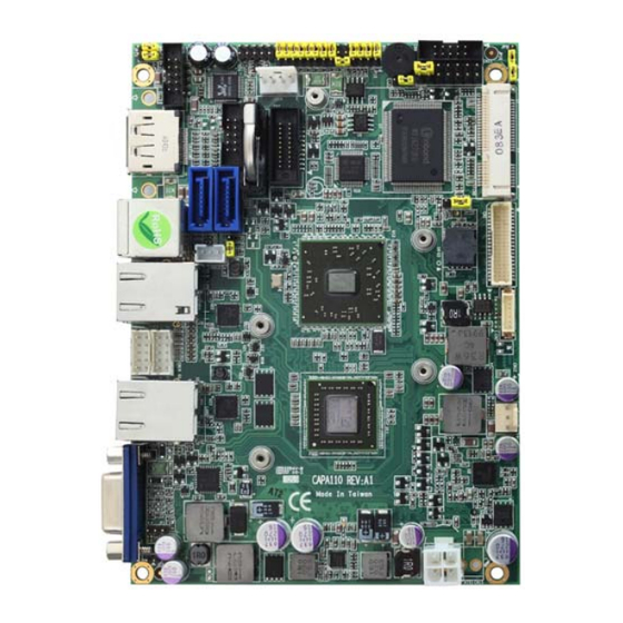
CAPA110/111 AMD Embedded G-Series Processor Capa Board with LVDS Chapter 2 Board Layout and Pin Assignments Board Dimensions and Fixing Holes Top Side Board Layout and Pin Assignments... - Page 13 CAPA110/111 AMD Embedded G-Series Processor Capa Board with LVDS Bottom Side Board Layout and Pin Assignments...
-
Page 14: Board Layout
CAPA110/111 AMD Embedded G-Series Processor Capa Board with LVDS Board Layout Top Side Board Layout and Pin Assignments... - Page 15 CAPA110/111 AMD Embedded G-Series Processor Capa Board with LVDS Bottom Side Board Layout and Pin Assignments...
-
Page 16: Jumper Settings
And remove jumper clip from 2 jumper pins to open. Below illustration shows how to set up jumper. Properly configure jumper settings on the CAPA110/111 to meet your application purpose. Below you can find a summary table of all jumpers and onboard default settings. -
Page 17: Restore Bios Optimal Defaults (Jp1)
CAPA110/111 AMD Embedded G-Series Processor Capa Board with LVDS 2.3.1 Restore BIOS Optimal Defaults (JP1) Put jumper clip to pin 2-3 for a few seconds then move it back to pin 1-2. Doing this procedure can restore BIOS optimal defaults. -
Page 18: Com1 Data/Power Selection (Jp7)
CAPA110/111 AMD Embedded G-Series Processor Capa Board with LVDS 2.3.5 COM1 Data/Power Selection (JP7) The COM1 port has +5V level power capability on DCD and +12V level on RI by setting this jumper. When COM1 is set to +5V or +12V level, please make sure the communication mode is RS-232 (see section 2.3.4). -
Page 19: Audio Output Selection (Jp13)
CAPA110/111 AMD Embedded G-Series Processor Capa Board with LVDS 2.3.9 Audio Output Selection (JP13) JP13 is to select line out or speaker out as source of audio output on audio connector CN10. When speaker out is used, it delivers 2W/channel continuous into 8 Ohm loads. -
Page 20: Connectors
CAPA110/111 AMD Embedded G-Series Processor Capa Board with LVDS Connectors Signals go to other parts of the system through connectors. Loose or improper connection might cause problems, please make sure all connectors are properly and firmly connected. Here is a summary table which shows all connectors on the hardware. -
Page 21: Power Connector (Atx1)
CAPA110/111 AMD Embedded G-Series Processor Capa Board with LVDS 2.4.1 Power Connector (ATX1) The ATX1 is a 4-pin power supply interface. External power supply plug fits into ATX1 in only one orientation. Properly press down power supply plug until it completely and firmly fits into this connector. - Page 22 CAPA110/111 AMD Embedded G-Series Processor Capa Board with LVDS 24bits single channel 18bits dual channel Signal Signal Signal Signal 1 VCCM VCCM VCCM VCCM VCCM VCCM VCCM VCCM VCCM VCCM VCCM VCCM N.C. N.C. N.C. N.C. 10 GND 10 GND 11 N.C.
-
Page 23: Inverter Connector (Cn2)
CAPA110/111 AMD Embedded G-Series Processor Capa Board with LVDS 2.4.3 Inverter Connector (CN2) The CN2 is DF13-7P-1.25V 7-pin connector for inverter. We strongly recommend you to use the matching DF13-7S-1.25C connector to avoid malfunction. Signal VBL1 (+12V level) VBL1 (+12V level) -
Page 24: Vga Connector (Cn4)
CAPA110/111 AMD Embedded G-Series Processor Capa Board with LVDS 2.4.5 VGA Connector (CN4) The CN4 is a standard slim type 15-pin D-Sub connector which is commonly used for CRT VGA monitor. This VGA interface configuration can be configured via software utility. -
Page 25: Pci-Express Mini Card Connector (Cn6)
CAPA110/111 AMD Embedded G-Series Processor Capa Board with LVDS 2.4.7 PCI-Express Mini Card Connector (CN6) CN6 is a PCI-Express Mini Card connector which supports a PCI-Express x1 link and a USB 2.0 link. A PCI-Express Mini Card can be applied to either PCI-Express or USB 2.0. -
Page 26: Com3 And Com4 Connector (Cn7)
No use No use The CN8 is a 2x5 pin box header (CAPA110 only). This connector is equipped with +5V level power capability on DCD and +12V level on RI by setting JP7 (see section 2.3.5). The pin assignment of RS-232/RS-422/RS-485 is listed on the following table. If you need COM1 port to support RS-422 or RS-485 mode, please refer to section 2.3.4. -
Page 27: Com2 Connector (Cn9)
CAPA110/111 AMD Embedded G-Series Processor Capa Board with LVDS 2.4.10 COM2 Connector (CN9) The COM2 port has +5V level power capability on DCD and +12V level on RI by setting JP11 (see section 2.3.7). The pin assignments are listed on the following table. -
Page 28: Cpu Fan Connector (Cn12)
CAPA110/111 AMD Embedded G-Series Processor Capa Board with LVDS ATX Power On/Off Button Pin 9 and 10 connect the ATX power button on front panel to the CPU card, which allows users to turn on or off ATX power supply. -
Page 29: Usb Connectors (Cn16 And Cn17)
CAPA110/111 AMD Embedded G-Series Processor Capa Board with LVDS 2.4.16 USB Connectors (CN16 and CN17) The 2x5 pin wafers are Universal Serial Bus (USB) connectors, CN16 and CN17. They are for installing versatile USB interface peripherals. The CN16 is designed with +5V level standby power which can provide power when system is in suspend mode. -
Page 30: Usb Connector (Usb1)
CAPA110/111 AMD Embedded G-Series Processor Capa Board with LVDS 2.4.18 USB Connector (USB1) The board features Universal Serial Bus (USB) connectors, compliant with USB 2.0 (480Mbps) that can be adapted to any USB peripherals, such as monitor, keyboard and mouse. This USB1 connector carries USB port 0 and 1. -
Page 31: Ethernet Ports (Lan1 And Lan2)
CAPA110/111 AMD Embedded G-Series Processor Capa Board with LVDS 2.4.20 Ethernet Ports (LAN1 and LAN2) Ethernet ports are RJ-45 connectors. Connection can be established by plugging one end of the ethernet cable into LAN1/LAN2 and the other end (phone jack) to a 1000/100/10-Base-T hub. -
Page 32: Chapter 3 Hardware Description
Linux environments. The system performance depends on the APU. BIOS The CAPA110/111 series use AMI Plug and Play BIOS with a single 16Mbit SPI Flash. System Memory The CAPA110/111 series support one 204-pin DDR3 SO-DIMM sockets for a maximum memory of 4GB DDR3 SDRAMs. -
Page 33: I/O Port Address Map
CAPA110/111 AMD Embedded G-Series Processor Capa Board with LVDS I/O Port Address Map The AMD G-Series APU communicates via I/O ports. Total 1KB port addresses are available for assigning to other devices via I/O expansion cards. Hardware Description... - Page 34 CAPA110/111 AMD Embedded G-Series Processor Capa Board with LVDS Hardware Description...
-
Page 35: Interrupt Controller (Irq) Map
CAPA110/111 AMD Embedded G-Series Processor Capa Board with LVDS Interrupt Controller (IRQ) Map The CAPA110/111 series are 100% PC compatible control boards which consist of 20 interrupt request lines. Four out of 20 can be programmable. The mapping list of the 20 interrupt request lines is shown as the following table. -
Page 36: Memory Map
CAPA110/111 AMD Embedded G-Series Processor Capa Board with LVDS Memory Map The memory mapping list is shown as follows: Hardware Description... - Page 37 CAPA110/111 AMD Embedded G-Series Processor Capa Board with LVDS This page is intentionally left blank. Hardware Description...
-
Page 38: Chapter 4 Ami Bios Setup Utility
CAPA110/111 AMD Embedded G-Series Processor Capa Board with LVDS Chapter 4 AMI BIOS Setup Utility The AMI UEFI BIOS provides users with a built-in setup program to modify basic system configuration. All configured parameters are stored in a 16MB flash chip to save the setup information whenever the power is turned off. -
Page 39: Main Menu
CAPA110/111 AMD Embedded G-Series Processor Capa Board with LVDS Hot Keys Description The Left and Right <Arrow> keys allow you to select a setup screen. Left/Right The Up and Down <Arrow> keys allow you to select a setup screen or Up/Down sub-screen. -
Page 40: Advanced Menu
CAPA110/111 AMD Embedded G-Series Processor Capa Board with LVDS System Language Use this item to choose the system default language. System Date/Time Use this option to change the system time and date. Highlight System Time or System Date using the <Arrow> keys. Enter new values through the keyboard. Press the <Tab>... - Page 41 CAPA110/111 AMD Embedded G-Series Processor Capa Board with LVDS ACPI Settings You can use this screen to select options for the ACPI configuration, and change the value of the selected option. A description of the selected item appears on the right side of the screen.
- Page 42 CAPA110/111 AMD Embedded G-Series Processor Capa Board with LVDS CPU Configuration This screen shows the CPU Configuration, and you can change the value of the selected option. Node 0 Information View memory information related to Node 0. IDE Configuration In the IDE Configuration menu, you can see the currently installed hardware in the SATA ports.
- Page 43 CAPA110/111 AMD Embedded G-Series Processor Capa Board with LVDS USB Configuration You can use this screen to select options for the USB Configuration, and change the value of the selected option. A description of the selected item appears on the right side of the screen.
- Page 44 CAPA110/111 AMD Embedded G-Series Processor Capa Board with LVDS USB transfer time-out The time-out value for control, bulk and interrupt transfers. Device reset time-out USB mass storage device start unit command time-out. Device power-up delay Maximum time the device will take before it properly reports itself to the host controller.
- Page 45 CAPA110/111 AMD Embedded G-Series Processor Capa Board with LVDS W83627UHG Super IO Configuration W83627UHG Serial Port Configuration The configuration of serial port 1~4 are set <Enabled> as default. AMI BIOS Setup Utility...
- Page 46 CAPA110/111 AMD Embedded G-Series Processor Capa Board with LVDS H/W Monitor This screen monitors hardware health. This screen displays the temperature of system and CPU, cooling fan speed in RPM and system voltages (VCORE, +12V, +5V and +3.3V). AMI BIOS Setup Utility...
-
Page 47: Chipset Menu
CAPA110/111 AMD Embedded G-Series Processor Capa Board with LVDS Chipset Menu The Chipset menu allows users to change the advanced chipset settings. You can select any of the items in the left frame of the screen to go to the sub menus: ►... - Page 48 CAPA110/111 AMD Embedded G-Series Processor Capa Board with LVDS AMI BIOS Setup Utility...
- Page 49 CAPA110/111 AMD Embedded G-Series Processor Capa Board with LVDS Memory Configuration All of options are set Auto as default. Node 0 Information This item is to provide user with the information of current using DDRIII SDRAMs. North Bridge LVDS Config Select <CAPA110 only>...
- Page 50 DP0 Output Mode Use this item to enable LVDS. DP1 Output Mode Use this item to choose Display Port output or disable mode (CAPA110 only). LVDS Panel Config Select Use this item to select configuration for LVDS panel if DP0 enable LVDS.
- Page 51 CAPA110/111 AMD Embedded G-Series Processor Capa Board with LVDS South Bridge This screen allows users to configure South Bridge chipset. For items marked with “ ”, please press <Enter> for more options. ► SB SATA Configuration ► SB USB Configuration ►...
-
Page 52: Boot Menu
CAPA110/111 AMD Embedded G-Series Processor Capa Board with LVDS Boot Menu The Boot menu allows users to change boot options of the system. Setup Prompt Timeout Number of seconds to wait for setup activation key. 65535(0xFFFF) means indefinite waiting. Bootup NumLock State Use this item to select the power-on state for the NumLock. -
Page 53: Security Menu
CAPA110/111 AMD Embedded G-Series Processor Capa Board with LVDS Security Menu The Security menu allows users to change the security settings for the system. Administrator Password This item indicates whether an administrator password has been set (installed or uninstalled). User Password This item indicates whether an user password has been set (installed or uninstalled). -
Page 54: Save & Exit Menu
CAPA110/111 AMD Embedded G-Series Processor Capa Board with LVDS Save & Exit Menu The Save & Exit menu allows users to load your system configuration with optimal or fail-safe default values. Save Changes and Exit When you have completed the system configuration changes, select this option to leave Setup and return to Main Menu. - Page 55 CAPA110/111 AMD Embedded G-Series Processor Capa Board with LVDS Discard Changes Select this option to quit Setup without making any permanent changes to the system configuration. Select Discard Changes from the Save & Exit menu and press <Enter>. Select Yes to discard changes.
-
Page 56: Appendix A Watchdog Timer
CAPA110/111 AMD Embedded G-Series Processor Capa Board with LVDS Appendix A Watchdog Timer About Watchdog Timer Software stability is major issue in most application. Some embedded systems are not watched by human for 24 hours. It is usually too slow to wait for someone to reboot when computer hangs. -
Page 57: Sample Program
CAPA110/111 AMD Embedded G-Series Processor Capa Board with LVDS Sample Program Assembly sample code : ;Enable WDT: dx,2Eh al,87 ;Un-lock super I/O dx,al dx,al ;Select Logic device: dx,2Eh al,07h dx,al dx,2Fh al,08h dx,al ;Activate WDT: dx,2Eh al,30h dx,al dx,2Fh al,01h dx,al ;Set Second or Minute :... - Page 58 CAPA110/111 AMD Embedded G-Series Processor Capa Board with LVDS If N=08h, the time base is set to minute. M = time value 00: Time-out Disable 01: Time-out occurs after 1 minute 02: Time-out occurs after 2 minutes 03: Time-out occurs after 3 minutes...
- Page 59 CAPA110/111 AMD Embedded G-Series Processor Capa Board with LVDS This page is intentionally left blank. Watchdog Timer...
-
Page 60: Appendix B Digital I/O
CAPA110/111 AMD Embedded G-Series Processor Capa Board with LVDS Appendix B Digital I/O About Digital I/O The onboard digital I/O has 8 bits (DIO0~7). Each bit can be set to function as input or output by software programming. In default, all pins are pulled high with +5V level (according to main power). - Page 61 CAPA110/111 AMD Embedded G-Series Processor Capa Board with LVDS dx,al dx,2Fh al,02h dx,al ;Programming DIO as in/out. dx,2Eh al,0E0h dx,al dx,2Fh al,Nh ;If N=07h, DIO is programmed as 3 inputs Note1 dx,al ;and 5 outputs (see below Digital Input: ;Read digital input data.
- Page 62 CAPA110/111 AMD Embedded G-Series Processor Capa Board with LVDS When DIO0~2 are connected to external device, the device sets DIO0~2 to high DIO7 DIO6 DIO5 DIO4 DIO3 DIO2 DIO1 DIO0 Output Output Output Output Output When DIO0~2 are connected to external device, the device sets DIO0 to low and DIO1~2 to high...
Need help?
Do you have a question about the CAPA110 and is the answer not in the manual?
Questions and answers