Table of Contents
Advertisement
Quick Links
Advertisement
Table of Contents

Related Manuals for VIA Technologies EPIA-P900


Summary of Contents for VIA Technologies EPIA-P900
- Page 2 USER MANUAL EPIA-P900 Pico-ITX embedded board 1.10-11012011-182900...
- Page 3 The information and product specifications within this document are subject to change at any time, without notice and without obligation to notify any person of such change. VIA Technologies, Inc. reserves the right the make changes to the products described in this manual at any time without prior notice.
- Page 4 Battery Recycling and Disposal Only use the appropriate battery specified for this product. Do not re-use, recharge, or reheat an old battery. Do not attempt to force open the battery. Do not discard used batteries with regular trash. Discard used batteries according to local regulations. Safety Precautions Always read the safety instructions carefully.
- Page 5 EPIA-P900 User Manual Box Contents and Ordering Information EPIA-P900-10 1 x EPIA-P900 embedded board (with VIA Eden™ X2 U4200 @ 1.0+ GHz NanoBGA2 processor) 1 x P830-A I/O card (pre-assembled companion card) 1 x SATA data cable (P/N: 99G33-240103) 1 x SATA power cable (P/N: 99G33-020985)
-
Page 6: Table Of Contents
EPIA-P900 User Manual Table of Contents Product Overview....................1 1.1. Key Features and Benefits................2 ™ 1.1.1. VIA Eden X2 Processor ............... 2 1.1.2. VIA VX900H Chipset................2 1.1.3. Expansion Option ................... 2 1.2. Product Specifications................. 3 1.3. Layout Diagram ..................... 5 1.4. - Page 7 EPIA-P900 User Manual Expansion Slots ....................31 4.1. PCIe and USB Combination Connector..........31 4.2. DDR3 SODIMM Memory Slot..............33 4.2.1. Installing a Memory Module .............. 34 4.2.2. Removing a Memory Module............. 36 Hardware Installation ..................37 5.1. Removing and Installing the P830-A Companion Card..... 37 5.1.1.
- Page 8 A.1.4. Power DVD 10 to Player MPEG2 1080P_40M Movie ......74 A.1.5. Idle at Windows 7 x64 ................74 A.1.6. Suspend S1....................74 A.1.7. Suspend S3....................74 A.1.8. Suspend S4....................75 A.1.9. Suspend S5....................75 Appendix B. Pin Header and Connector Vendor Lists........... 77 B.1. EPIA-P900 Mainboard ..................77...
- Page 9 EPIA-P900 User Manual Lists of Figures Figure 1: Layout diagram of the EPIA-P900 mainboard (top and bottom view) 5 Figure 2: Mounting holes and dimensions of the EPIA-P900 ........7 Figure 3: Height distribution of the EPIA-P900 mainboard........8 Figure 4: External I/O ports..................... 9 Figure 5: HDMI port pinout diagram................
- Page 10 EPIA-P900 User Manual Figure 40: Suggested minimum internal chassis ceiling height......43 Figure 41: Suggested keepout areas ................44 Figure 42: Illustration of the Main menu screen............46 Figure 43: Illustration of the Advanced Settings screen......... 48 Figure 44: Illustration of the CPU Configuration screen......... 49 Figure 45: Illustration of SATA Configuration screen ..........
- Page 11 EPIA-P900 User Manual Lists of Tables Table 1: Layout diagram description table of the EPIA-P900 mainboard.... 6 Table 2: Layout diagram description table of external I/O ports ......9 Table 3: HDMI port pinout ................... 10 Table 4: VGA port pinout ..................... 11 Table 5: USB 2.0 port pinout..................
-
Page 12: Product Overview
Technology. The VIA EPIA-P900 includes one 1066 MHz DDR3 SODIMM slot that support up to 4 GB memory size. The VIA EPIA-P900 provides support for high fidelity audio with its included VIA VT2021 High Definition Audio codec. In addition it supports two SATA 3Gb/s storage devices and fully compatible with ®... -
Page 13: Key Features And Benefits
1.1.3. Expansion Option The EPIA-P900 further proves its versatility by providing an expansion option connector that uses a “PCIe and USB 2.0 combinations board-to-board connector” for P830-B expansion card. The P830-B expansion card provides two Mini-PCIe x1 slots. -
Page 14: Product Specifications
EPIA-P900 User Manual 1.2. Product Specifications Processor VIA Eden X2 1.0+ GHz NanoBGA2 (for EPIA-P900-10 SKU) Supports 800MHz Front Side Bus X86 and x64 compatible 21 mm x 21 mm FCBGA Chipset VIA VX900H Unified Digital Media IGP chipset ... - Page 15 EPIA-P900 User Manual Back Panel I/O 1 x HDMI port 1 x VGA port (on P830-A) 1 x GigaLAN port (on P830-A) 2 x USB 2.0 ports (on P830-A) BIOS AMI BIOS 8 Mbit SPI flash memory ...
-
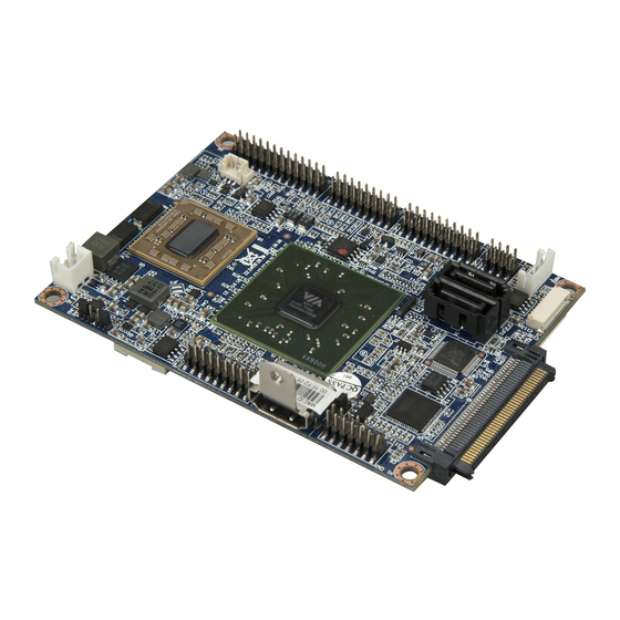
Page 16: Layout Diagram
EPIA-P900 User Manual 1.3. Layout Diagram Figure 1: Layout diagram of the EPIA-P900 mainboard (top and bottom view) -
Page 17: Table 1: Layout Diagram Description Table Of The Epia-P900 Mainboard
JM3: Backlight power selector PWR1: DC-in power connector VIA Eden X2 CPU J2: UART port 1 SODIMM1: DDR3 SODIMM slot LVDS1: LVDS connector BAT1: CMOS battery connector J3: SPI connector Table 1: Layout diagram description table of the EPIA-P900 mainboard... -
Page 18: Product Dimensions
EPIA-P900 User Manual 1.4. Product Dimensions 100.00 82.00 66.60 25.00 1.87 8.20 15.10 13.38 8.10 Figure 2: Mounting holes and dimensions of the EPIA-P900... -
Page 19: Height Distribution
EPIA-P900 User Manual 1.5. Height Distribution Figure 3: Height distribution of the EPIA-P900 mainboard... -
Page 20: I/O Interface
EPIA-P900 User Manual 2. I/O Interface The VIA EPIA-P900 has a wide selection of interfaces. It includes a selection of frequently used ports as part of the external I/O coastline. 2.1. External I/O Ports Figure 4: External I/O ports Item... -
Page 21: Hdmi Port
EPIA-P900 User Manual 2.1.1. HDMI Port The integrated 19-pin HDMI port uses an HDMI Type A receptacle connector as defined in the HDMI 1.2 specification. The HDMI port is for connecting to HDMI displays. The pinout of the HDMI port is shown below. -
Page 22: Vga Port
EPIA-P900 User Manual 2.1.2. VGA Port The 15-pin VGA port uses a female DE-15 connector. The VGA port is for connecting to analog displays. The pinout of the VGA port is shown below. Figure 6: VGA port pinout diagram Signal... -
Page 23: Usb 2.0 Port
EPIA-P900 User Manual 2.1.3. USB 2.0 Port There are two integrated USB 2.0 ports located below the RJ45 LAN port at the external I/O panel. The USB 2.0 interface port gives complete Plug and Play and hot swap capability for external devices and it complies with USB UHCI, rev. -
Page 24: Onboard Connectors
EPIA-P900 User Manual 2.2. Onboard Connectors 2.2.1. LVDS Connector The mainboard has one 24-pin LVDS panel connector on the bottom side. The onboard LVDS panel connector allows to connect the panel’s LVDS cable to support the single-channel 18-bit/24-bit display. Backlight controls are integrated into the LVDS panel connector pinout. -
Page 25: Vga And Usb Combination Pin Header
EPIA-P900 User Manual 2.2.2. VGA and USB combination pin header The VGA and USB combination pin header block labeled as VGA_USB1 is used to connect to the P830-A companion card. The pin header block provides support for one VGA port and two USB 2.0 ports. The pinout of the VGA and USB combination pin header is shown below. -
Page 26: Sata Connectors
EPIA-P900 User Manual 2.2.3. SATA Connectors The two SATA connectors onboard can support up to 3 Gb/s transfer speeds. Both SATA connectors have a 7th pin that can provide +5V power to a SATA Disk-on-Module (DOM). When a regular SATA hard drive is connected, the 7 pin will be a ground pin. -
Page 27: Sata Power Connector
EPIA-P900 User Manual 2.2.4. SATA Power Connector The onboard SATA power connector provides both +5V and +12V directly through the mainboard to the SATA drives. The SATA power connector is labeled as “PWR2”. The pinout of the SATA power connector is shown below. -
Page 28: Usb And Usb Device Combination Pin Header
EPIA-P900 User Manual 2.2.5. USB and USB Device Combination Pin Header The mainboard has one USB and USB Device combination pin header block enables the addition of five more USB 2.0 ports and one USB Device port. The pin header block is labeled as “CN2”. The pinout of the pin header is shown below. -
Page 29: Lan Pin Header
EPIA-P900 User Manual 2.2.6. LAN pin header The onboard LAN pin header block is used to connect to the P830-A companion card. The pin header block labeled as “CN3” provides support for one RJ45 Gigabit Ethernet port. The pin header pinout is shown below. -
Page 30: Uart Connectors
EPIA-P900 User Manual 2.2.7. UART Connectors The mainboard includes two UART ports: UART port 1 labeled as “J2” is the 12-pin port on the bottom side. UART port 2 labeled as “J1” is the 10-pin port on the top side. The UART ports can be used to attach an additional port for serial devices. -
Page 31: Lpc, Smbus, And Gpio Combination Pin Header
EPIA-P900 User Manual 2.2.8. LPC, SMBus, and GPIO Combination Pin Header The mainboard includes one LPC, SMBus, and GPIO combination pin header block labeled as “CN5”. The combination pin header is for connecting LPC, SMBus devices and General Purpose Input and Output. The pinout of the pin header is shown below. -
Page 32: Spi Flash Connector
EPIA-P900 User Manual 2.2.9. SPI Flash Connector The mainboard has one 8-pin SPI flash connector. The SPI (Serial Peripheral Interface) flash connector is used to connect to the SPI BIOS programming fixture for updating the SPI flash ROM. The connector is labeled as “J3”. The pinout of the connector is shown below. -
Page 33: Cmos Battery Connector
EPIA-P900 User Manual 2.2.10. CMOS Battery Connector The mainboard is equipped with onboard CMOS battery connector used for connecting the external cable battery that provides power to the CMOS RAM. If disconnected all configurations in the CMOS RAM will be reset to factory defaults. -
Page 34: Front Panel And Ps2 Combination Pin Header
EPIA-P900 User Manual 2.2.11. Front Panel and PS2 Combination Pin Header The mainboard includes one Front Panel and PS2 combination pin header block labeled as “CN4”.The front panel and PS2 combination pin header is used to connect the power switch, reset switch, power LED, suspend LED, HDD LED, case speaker, PS2 keyboard port and PS2 mouse port. -
Page 35: Front Audio Pin Header
EPIA-P900 User Manual 2.2.12. Front Audio Pin Header The mainboard has front audio pin header that used for connecting the Line- Out, Line-In and MIC-In jacks. The pin header is labeled as “CN1”. The pinout of the pin header is shown below. -
Page 36: Cpu Fan Connector
EPIA-P900 User Manual 2.2.13. CPU Fan Connector The CPU fan connector onboard runs on +5V and maintain CPU cooling. The fan provides variable fan speeds controlled by the BIOS. The CPU fan connector is labeled as “FAN1”. The pinout of the fan connector is shown below. -
Page 37: Dc-In Power Connector
EPIA-P900 User Manual 2.2.14. DC-In Power Connector The mainboard has an onboard DC-In 2-pin power connector to connect the DC-In power cable. The DC-In power connector is labeled as “PWR1”. The pinout of the DC-In power connector is shown below. -
Page 38: Jumpers
EPIA-P900 User Manual 3. Jumpers 3.1. Clear CMOS Jumper The onboard CMOS RAM stores system configuration data and has an onboard battery power supply. To reset the CMOS settings, set the jumper on pins 2 and 3 while the system is off. Return the jumper to pins 1 and 2 afterwards. -
Page 39: Panel Power Select Jumper
EPIA-P900 User Manual 3.2. Panel Power Select Jumper The mainboard has a jumper that controls the voltage delivered to the LVDS panel connector. The jumper is labeled as “PVDD1”. The jumper settings are shown below. VIA Eden X2 VX900H +3.3V... -
Page 40: Backlight Power Select Jumper
EPIA-P900 User Manual 3.3. Backlight Power Select Jumper The mainboard has a jumper that controls the input voltage delivered to the LVDS inverter connector. The jumper is labeled as “IVDD_SEL1”. The jumper settings are shown below. VIA Eden X2 VX900H... -
Page 42: Expansion Slots
EPIA-P900 User Manual 4. Expansion Slots 4.1. PCIe and USB Combination Connector The onboard PCIe and USB combination connector labeled “CN6”is for connecting directly to the P830-B expansion card. The connector pinout supports two Mini PCIe x1 (supports USB 2.0). -
Page 43: Table 25: Pcie And Usb Combination Connector Pinout
EPIA-P900 User Manual PETP9 PEXRX9+ PETN8 PEXRX8- PETP8 PEXRX8+ PE2CLK- PE2CLK+ Table 25: PCIe and USB combination connector pinout... -
Page 44: Ddr3 Sodimm Memory Slot
EPIA-P900 User Manual 4.2. DDR3 SODIMM Memory Slot The mainboard provide one 204-pin DDR3 SODIMM slot that supports non- ECC DDR3 1066/800 SODIMM memory modules. The memory slot can accommodate up to 4 GB of DDR3 1066/800 memory. The memory slot is labeled as “SODIMM1”. -
Page 45: Installing A Memory Module
EPIA-P900 User Manual 4.2.1. Installing a Memory Module Step 1 Align the notch on the SODIMM memory module with the protruding wedge on the SODIMM memory slot. Insert the SODIMM memory module at a 30 degree angle relative to the SODIMM memory slot. -
Page 46: Figure 30: Installing Memory Thermal Pad
EPIA-P900 User Manual Step 3 Install the memory thermal pad on the top of the DRAM memory module. Figure 30: Installing memory thermal pad The memory thermal pad is used for memory cooling, and to ensure the operating temperature of the memory module should not exceed to 60°C. -
Page 47: Removing A Memory Module
EPIA-P900 User Manual 4.2.2. Removing a Memory Module Step 1 To disengage the locking clips, push the locking clips horizontally outward away from the SODIMM memory module. Figure 31: Disengaging the SODIMM locking clips Step 2 When the locking clips have cleared, the SODIMM memory module will automatically pop up to the 30 degree angle. -
Page 48: Hardware Installation
EPIA-P900 User Manual 5. Hardware Installation 5.1. Removing and Installing the P830-A Companion Card The VIA EPIA-P900 mainboard comes with pre-installed P830-A companion card. The pre-installed P830-A companion card is connected through VGA_USB1 and CN3 pin headers. 5.1.1. Removing the P830-A Step 1 Remove the two screws that secure the P830-A companion card. -
Page 49: Figure 34: Pulling The P830-A Companion Card
EPIA-P900 User Manual Step 2 Gently pull up the P830-A companion card apart from the EPIA-900 mainboard. As you pull the companion card, keep the card evenly aligned to avoid bending the pin headers (VGA_USB and LAN pin) on the mainboard. -
Page 50: Installing The P830-A
Align the CON1 and CON2 board-to-board connectors on the P830-A with the VGA_USB1 combination pin header block and LAN pin header (CN3) block on the EPIA-P900 mainboard, respectively. In the figure below, the dotted rectangles represent the CON1 and CON2 connectors on the bottom... -
Page 51: Figure 36: Connecting P830-A Companion Card
P900 mainboard have been fully inserted into the CON1 and CON2 board-to- board connectors of the P830-A companion card. Figure 36: Connecting P830-A companion card Step 3 Secure the EPIA-P830-A to the EPIA-P900 with two screws. Figure 37: Securing the P830-A companion card... -
Page 52: Installing The P830-B Expansion Card
5.2. Installing the P830-B Expansion Card Step 1 Align the PCIe and USB 2.0 combination connector (CN6) on the EPIA-P900 with the CN2 board-to-board female connector on the P830-B expansion card. Then gently insert the CN6 connector into the CN2 connector until the CN6 connector is fully inserted. -
Page 53: Installing Into A Chassis
EPIA-P900 User Manual 5.3. Installing into a Chassis The EPIA-P900 can be fitted into any chassis that has the mounting holes for compatible with the standard Pico-ITX mounting hole locations. Additionally, the chassis must meet the minimum height requirements for specified areas of the mainboard. -
Page 54: Suggested Minimum Chassis Height
In getting the minimum height requirements for internal space of the chassis, it is required to consider the heights of the connectors (such as SPI connector, LVDS panel connector and DDR3 SODIMM slot) on the bottom side of the EPIA-P900 mainboard. -
Page 55: Suggested Keepout Areas
EPIA-P900 User Manual 5.3.3. Suggested keepout areas The figure below shows the areas of the mainboard that is highly suggested to leave unobstructed. Figure 41: Suggested keepout areas... -
Page 56: Bios Setup Utility
EPIA-P900 User Manual 6. BIOS Setup Utility 6.1. Entering the BIOS Setup Utility Power on the computer and press Delete during the beginning of the boot sequence to enter the BIOS Setup Utility. If the entry point has passed, restart the system and try again. -
Page 57: System Overview
EPIA-P900 User Manual 6.4. System Overview The System Overview screen is the default screen that is shown when the BIOS Setup Utility is launched. This screen can be accessed by traversing the navigation bar to the “Main” label. BIOS SETUP UTILITY... -
Page 58: System Date
EPIA-P900 User Manual 6.4.5. System Date This section shows the current system date. Press Tab to traverse right and Shift+Tab to traverse left through the month, day, and year segments. The + and - keys on the number pad can be used to change the values. The weekday name is automatically updated when the date is altered. -
Page 59: Advanced Settings
EPIA-P900 User Manual 6.5. Advanced Settings The Advanced Settings screen shows a list of categories that can provide access to a sub-screen. Sub-screen links can be identified by the preceding right-facing arrowhead. BIOS SETUP UTILITY Main Advanced Boot Security Exit Advanced Settings Configure CPU. -
Page 60: Cpu Configuration
EPIA-P900 User Manual 6.5.1. CPU Configuration The CPU Configuration screen shows detailed information about the built-in processor. In addition to the processor information, the thermal controls can be set. BIOS SETUP UTILITY Advanced Configure advanced CPU settings Module Version 01.08... -
Page 61: Sata Configuration
EPIA-P900 User Manual 6.5.2. SATA Configuration The SATA Configuration screen shows links to the primary and secondary SATA hard drive information screens. BIOS SETUP UTILITY Advanced SATA Configuration While entering setup, BIOS auto detects the Serial ATA IDE devices presence of SATA devices. - Page 62 EPIA-P900 User Manual In addition, the PIO and DMA modes may be configured for each SATA hard drive. 6.5.2.1.1. PIO Mode The PIO Mode has six possible settings: Auto, 0, 1, 2, 3, and 4. The “Auto” setting enables the BIOS to autonomously determine the appropriate PIO mode for the hard drive.
-
Page 63: Superio Configuration
EPIA-P900 User Manual 6.5.3. SuperIO Configuration The SuperIO Configuration screen shows the specific addresses and IRQs of the onboard serial ports. BIOS SETUP UTILITY Advanced Configure F81865F Super IO Chipset Allows BIOS to select Serial Port1 base Serial Port1 Address [3F8/IRQ4] addresses. -
Page 64: Hardware Health Configuration
EPIA-P900 User Manual 6.5.4. Hardware Health Configuration The Hardware Health Configuration screen has no editable fields. The system temperature is taken from an optional sensor that is connected to the J5 pin header. BIOS SETUP UTILITY Advanced Hardware Health Configuration... -
Page 65: Acpi Configuration
EPIA-P900 User Manual 6.5.5. ACPI Configuration Advanced Configuration and Power Interface (ACPI) grants the operating system direct control over system power management. The ACPI Configuration screen can be used to set a number of power management related functions. BIOS SETUP UTILITY... -
Page 66: Apm Configuration
EPIA-P900 User Manual 6.5.6. APM Configuration Advanced Power Management (APM) enables the operating system to co- work with the BIOS to control the system power management. The APM Configuration screen can be used to set a number of power management functions. - Page 67 EPIA-P900 User Manual 6.5.6.2. Restore on AC/Power Loss Restore on AC/Power Loss defines how the system will respond after AC power has been interrupted while the system is on. There are three options. Power Off The Power Off option keeps the system in an off state until the power button is pressed again.
- Page 68 EPIA-P900 User Manual 6.5.6.4. Resume on KBC Resume on KBC wakes up a system that has been put into suspend or standby mode. When this feature is enabled, keyboard activity as defined in the Wake- Up Key feature will cause the system to wake up. This feature has three options.
- Page 69 EPIA-P900 User Manual 6.5.6.7. Resume on Mouse Resume on Mouse wakes up a system that has been put into suspend or standby mode. When this feature is enabled, any mouse activity that is detected will cause the system to wake up. This feature has three options.
-
Page 70: Event Log Configuration
EPIA-P900 User Manual 6.5.7. Event Log Configuration The Event Logging Configuration screen displays three features for accessing, modifying, and deleting event logs. BIOS SETUP UTILITY Advanced Event Logging details View all unread events on the Event Log. View Event Log... -
Page 71: Spread Spectrum Configuration
EPIA-P900 User Manual 6.5.8. Spread Spectrum Configuration The Spread Spectrum Configuration screen enables access to the Spread Spectrum Setting feature. BIOS SETUP UTILITY Advanced Spread Spectrum Configuration Dynamic to adjust SSC. CPU Spread Spectrum Setting [0.1%] Select Screen Select Item... -
Page 72: Usb Configuration
EPIA-P900 User Manual 6.5.9. USB Configuration The USB Configuration screen shows the number of connected USB devices. Additionally, support for various USB features can be enabled or disabled. BIOS SETUP UTILITY Advanced USB Configuration Enables USB device mode. Module Version - 2.24.5-13.4... -
Page 73: Crb Configuration
EPIA-P900 User Manual 6.5.10. CRB Configuration The CRB Configuration screen includes several chipset settings. BIOS SETUP UTILITY Advanced DRAM Clock [Auto] Options Select Display Device 1 [CRT] Select Display Device 2 [HDMI] Auto Panel Type [02] 400 MHz VGA Share Memory (Frame Buffer) -
Page 74: Table 27: Panel Types Resolution
EPIA-P900 User Manual 6.5.10.3. Panel Type This feature enables the user to specify the resolution of the display being used with the system. The panel types are predefined in the VGA VBIOS. Panel Type Resolution Panel Type Resolution 640 x 480... - Page 75 EPIA-P900 User Manual 6.5.10.9. Backlight Control The Backlight Control feature enables the user to control the brightness of the LCD backlight. This feature has four options. Level 1 25% Light Level 2 50% Light Level 3 75% Light Level 4 100% Light 6.5.10.10.
-
Page 76: Boot Settings
EPIA-P900 User Manual 6.6. Boot Settings The Boot Settings screen has a single link that goes to the Boot Settings Configuration and Boot Device Priority screens. BIOS SETUP UTILITY Main Advanced Boot Security Exit Boot Settings Configure Settings during System Boot. - Page 77 EPIA-P900 User Manual 6.6.1.1. Quick Boot The Quick Boot feature enables the BIOS to skip certain tests in order to speed up the boot sequence. This feature has two options: enabled and disabled. 6.6.1.2. Quiet Boot The Quiet Boot feature hides all of the Power-on Self Test (POST) messages during the boot sequence.
-
Page 78: Boot Device Priority
EPIA-P900 User Manual 6.6.2. Boot Device Priority The Boot Device Priority screen lists all bootable devices. BIOS SETUP UTILITY Boot Boot Device Priority Specifies the best sequence from the 1st Boot Device [Network: VIA Networking] available devices. A device enclosed in... -
Page 79: Security Settings
EPIA-P900 User Manual 6.7. Security Settings The Security Settings screen provides a way to restrict access to the BIOS or even the entire system. BIOS SETUP UTILITY Security Settings Install or Change the password. Supervisor Password : Not Installed User Password... -
Page 80: Password Check
EPIA-P900 User Manual 6.7.4. Password Check This feature is compulsory when the Change Supervisor Password option is set. The user will have up to three chances to enter the correct password before the BIOS forces the system to stop booting. If the user does not enter the correct password, the keyboard will also lock up. -
Page 81: Exit Options
EPIA-P900 User Manual 6.8. Exit Options BIOS SETUP UTILITY Exit Options Exit system setup after saving the changes. Save Changes and Exit Discard Changes and Exit F10 key can be used for Discard Changes this operation. Load Optimal Defaults Select Screen... -
Page 82: Driver Installation
EPIA-P900 User Manual 7. Driver Installation 7.1. Microsoft Driver Support The VIA EPIA-P900 mainboard is compatible with Microsoft operating systems. The latest Windows drivers can be downloaded from the VEPD website at www.viaembedded.com. For embedded operating systems, the related drivers can be found in the VIA Embedded website at www.viaembedded.com. -
Page 84: Appendix A. Power Consumption Report
EPIA-P900 User Manual Appendix A. Power Consumption Report Power consumption tests were performed on the VIA EPIA-P900. The following tables represent the breakdown of the voltage, ampere and wattage values while running common system applications. A.1. EPIA-P900-10 The tests were performed based on the following additional components: ™... -
Page 85: Power Dvd 10 To Player H.264 1080I_10M Movie
EPIA-P900 User Manual A.1.3. Power DVD 10 to Player H.264 1080i_10M Movie Test Condition Volts Amperes Watts Maximum 12.16 2.084 25.341 Average 12.06 1.489 17.957 Minimum 11.56 1.040 12.022 A.1.4. Power DVD 10 to Player MPEG2 1080P_40M Movie Test Condition... -
Page 86: Suspend S4
EPIA-P900 User Manual A.1.8. Suspend S4 Test Condition Volts Amperes Watts Maximum 12.28 0.076 0.933 Average 12.27 0.074 0.908 Minimum 12.24 0.072 0.881 A.1.9. Suspend S5 Test Condition Volts Amperes Watts Maximum 12.28 0.076 0.933 Average 12.26 0.073 0.895 Minimum 12.24... -
Page 88: Appendix B. Pin Header And Connector Vendor Lists
LPC, SMBus, and GPIO Neltron 2208SM-26G-BK-CP combination connector PCI Express and USB Samtec ERM8-040-01-L-D-EM2-TR combination connector Clear CMOS jumper Neltron 2199SA-03G-301523 Panel power select jumper Neltron 2199SA-03G-301523 Backlight power select jumper Neltron 2199SA-03G-301523 Table 28: EPIA-P900 pin header and connector vendor lists... - Page 89 Taiwan Headquarters Europe 1F, 531 Zhong-Zheng Road 940 Mission Court In den Dauen 6 Xindian District, New Taipei City 231, Fremont, CA 94539 53117 Bonn Taiwan Germany TEL: 886.2.2218.5452 TEL: 1.510.683.3300 TEL: 49.228.688565.0 FAX: 886.2.2218.5453 FAX: 1.510.687.4654 FAX: 49.228.688565.19 Email: embedded@via.com.tw Email: embedded@viatech.com Email: embedded@via-tech.de China...
Need help?
Do you have a question about the EPIA-P900 and is the answer not in the manual?
Questions and answers