
Related Manuals for Videx IPVK Series


Summary of Contents for Videx IPVK Series
- Page 1 VIDEOKIT IPVK/6296 SERIES IP one way, two way videokit IPVK IPVKC Rev.0.1 Installation handbook We recommend 66550062-EN - V5.0 - 31/10/19 This equipment is installed by a Competent Electrician, Security or Communications Engineer.
-
Page 2: Table Of Contents
This manual has been written and revised carefully. The instruc- tions and the descriptions which are included in it are referred to VIDEX parts and are correct at the time of print. However, sub- sequent VIDEX parts and manuals, can be subject to changes without notice. -
Page 3: System Components And Available Versions
IPVK/6296 Series IP videokit System components and available versions IPVK/6296 Colour videokit. OUTDOOR INDOOR STATION STATION Videophone 135,0 45,0 22,7 Art. 6296 pag. 15 Camera unit Art. 4533 pag. 5 ACCESSORIES Power supply 15,7 Art. HDR-15-12 43,8 120,0 Flush Surface Mounting Mounting Fig. 1 - IPVK/6296 components (measures in mm) IPVK-1/6296 - flush mounting 1 Outdoor station composed of: 1 Colour videophone... - Page 4 IPVK/6296 Series IP videokit System components and available versions IPVKC/6296 Colour videokit plus a codelock module. OUTDOOR INDOOR STATION STATION 135,0 45,0 22,7 Videophone Art. 6296 pag. 15 Camera unit Art. 4533 pag. 5 ACCESSORIES Codelock Power supply module Art. HDR-15-12 Art. 4901 pag. 9 Flush Surface Mounting...
- Page 5 IPVK/6296 Series IP videokit Art. 4533 IP speaker unit module for VIDEX IP System Rev.0.1 4533-0 4533-1 4533-2 STEEL PROG. Close HIGH BRASS MATTE Open Made in Italy RS485 EXT CAMERA RELAY 1 RELAY 2 ETHERNET INPUTS EXPANSION BUTTONS EIA/TIA-568A or EIA/TIA-568B Fare riferimento alla tabella CONNESSIONE Fig.
- Page 6 • Microphone volume through the relevant trimmer; • Speaker volume through the relevant trimmer; • RS-485 connection termination. Art. 4533-0 Art. 4533-1 Art. 4533-2 For the module programming refer to the section VIDEX IP Wizard. CONNECTION EIA/TIA 568A 4533 signals RJ-45 pin PIN 1 - White-green TX–...
- Page 7 It is strongly recommended that this operation is carried out by a qualified engineer and in any case after a contact with Videx support. • Disconnect the door panel from the power supply.
- Page 8 IPVK/6296 Series IP videokit Art. 4533 IP speaker unit module for VIDEX IP System ADHESIVE GASKET PLACEMENT seal as shown in Fig. 14. Apply the ANTI TAMPERING LOCKS FIXING as shown in Fig. 15. Fit the anti-tampering locks Fig. 14 Fig. 15 HOW TO REMOVE/INSERT THE CARD NAME HOLDER •...
- Page 9 GENERAL DIRECTIONS FOR INSTALLATION In order to achieve the best results from the schematics described it is necessary to install only original VIDEX equipment, strictly keeping to the items indicated on each schematic and follow these General Directions for Installation: •...
-
Page 10: Art. 4901 Digital Codelock Module
IPVK/6296 Series IP videokit Art. 4901 Digital codelock module LOCK RELEASE BACK EMF PROTECTION A varistor must be fitted across the terminals on AC lock release (Fig. 3) and a diode must be fitted across the terminals on a DC lock release (Fig. - Page 11 IPVK/6296 Series IP videokit Art. 4901 Digital codelock module PROGRAMMING MODE 1 DEFAULT MODE, JPL = A PROGRAMMING MODE 2 Follow the steps below to set the codelock to mode 1: Follow the steps below to set the codelock to mode 2: 1.
- Page 12 IPVK/6296 Series IP videokit Art. 4901 Digital codelock module OPERATION • Type in the programmed code and press ENTER; • If the code is correct, the green LED will illuminate for approx. 2 seconds and the relay relevant to the code will operate for the programmed time;...
- Page 13 IPVK/6296 Series IP videokit 4000 Series Surface and flush mounting door station installation EXAMPLE: INSTALLING A FOUR MODULE OUTDOOR STATION fig. 1 fig. 2 fig. 3 fig. 4 fig. 5 fig. 6 fig. 7 fig. 8 fig. 9 fig. 10 fig.
- Page 14 IPVK/6296 Series IP videokit 4000 Series Surface and flush mounting door station installation INSTALLING A SURFACE MOUNT DOOR STATION 1. Place the surface box against the wall (165-170cm between the top of the box and the floor level as shown in Fig. 1) and mark the fixing holes for (fig. 2).
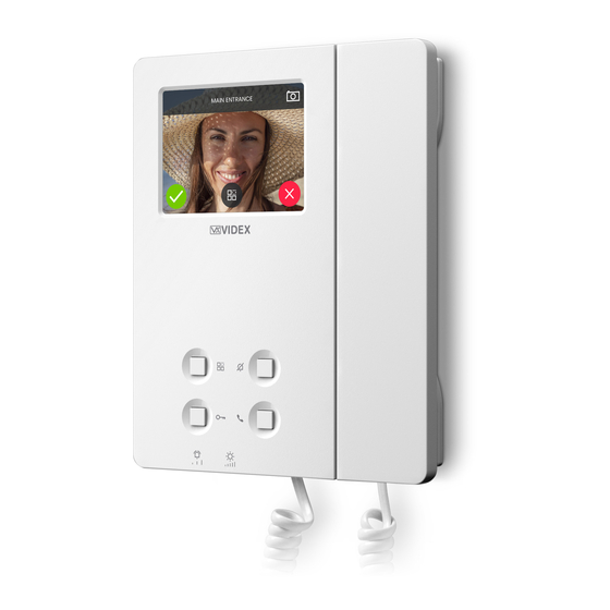
- Page 15 Fig. 1 Front Fig. 2 Back DESCRIPTION LEGEND IP Videophone specific for VIDEX IP System using 3.5” full colour 3,5” Touch screen active matrix LCD touch screen. Operating push buttons and LED’s The videophone includes 4 buttons with standard functions like Call tone volume control “privacy”, “door- open”, “camera recall”...
-
Page 16: Art. 6296 Ip Videophone For Videx Ip System
PUSH BUTTONS The button operation depends on the configuration carried out through the configuration software for VIDEX IP system “Videx IP Wizard”. Default button functions can be changed, the function of the button can be different depending on the current state of the videophone. - Page 17 IP Videophone for VIDEX IP System PROGRAMMING The button operation must be programmed through the configuration software for VIDEX IP system, however some operating parameters can be programmed through the videophones on screen menu. The “SETTINGS MENU” can be used to program some parameters and to carry out some adjustments.
- Page 18 IPVK/6296 Series IP videokit Art. 6296 IP Videophone for VIDEX IP System NUMBER OF RINGS • Tap on the rings icon (Fig. 5 on page 17). • The current value is shown (Fig. 11). • Swipe among the values to select the required value then tap on the tick button to confirm (Fig. 12).
- Page 19 IPVK/6296 Series IP videokit Art. 6296 IP Videophone for VIDEX IP System 15:30 ENTER ADMIN PASSWORD 15:30 SELECT A CALL POINT Main Entrance Back Entrance Fig. 15 Enter engineer password Fig. 16 Select the door panel to connect to 15:30 15:30...
- Page 20 IPVK/6296 Series IP videokit Art. 6296 IP Videophone for VIDEX IP System BINDING CODE • This menu option shows the binding code for the APP on your smartphone (iOS or Android) that allows you to bind the videophone to the smartphone. After the binding process, any call directed to the videophone will also be received on the smartphone.
- Page 21 IPVK/6296 Series IP videokit Art. 6296 IP Videophone for VIDEX IP System OPERATION VIDEOPHONE’S BUTTONS TO ANSWER A CALL & OPEN THE DOOR • On an incoming call the videophone rings and the display shows the initialising screen (Fig. 28), the video coming from the door panel is then shown (Fig.
- Page 22 IP Videophone for VIDEX IP System USING THE SERVICE BUTTON button operates only if previously set using the “Videx IP Wizard”. If it is pressed during the conversation or when the monitor is in stand-by, it will operate according to the setup made.
- Page 23 IPVK/6296 Series IP videokit Art. 6296 IP Videophone for VIDEX IP System SWITCHING BETWEEN DOOR PANEL CAMERA AND EXTERNAL VIDEO SOURCE The door panel allows the connection of an external video source for an external camera or a connection to a CCTV system.
- Page 24 • View the event log. * Note that the list of available door panels like the list of available extensions and the list of door panel relays are depending on the programming made using the “Videx IP Wizard” software. For every videophone, independent of each other, can list all or any combination of available devices on the system.
- Page 25 The intercommunicating call is possible to any intercom stored in the videophone’s “intercoms address book”. The “intercoms address book” is populated using the configuration software “Videx IP Wizard”. • Tap on the intercommunicating call icon (Fig. 53)*, if the “intercoms address book” is empty a warning is shown (Fig. 56).
- Page 26 IPVK/6296 Series IP videokit Art. 6296 IP Videophone for VIDEX IP System VIEW THE EVENT LOG The videophone stores a list of events (external calls and internal calls) with the event date & time. On any external call, the video- phone stores also a picture of the visitor. The events are described by 2 icons (a speaker unit for door panel events and an intercom for indoor station events) and 3 different colours:...
- Page 27 In case of firmware update failure (i.e. because of mains failure or cable disconnection during the update etc.) and the videophone is no longer recognised by the Videx IP Wizard software, you can try to restore it by manually putting it into boot mode.
- Page 28 IPVK/6296 Series IP videokit 6200 Series Videophone wall mounting instructions Fig. 1 Fig. 2 Fig. 3 Fig. 5 Fig. 4 Fig. 6 Fig. 7 1. In order to install the videophone, it is necessary to remove the cover, which contains all the electronics, from the base: firstly disconnect the handset from the videophone (by removing its plug from the videophone) then insert a 5.5mm flat screw driv- then rotate clockwise until you listen a “CLICK!”.
-
Page 29: Windows Setup Static Ip Address
DESCRIPTION In order to setup the Videx IP system the PC running the VIDEX IP wizard and all the VIDEX IP devices must be connected on the same LAN. Once the physical connection is made, the PC’s network card must be properly set and connected to the LAN mentioned above. To achieve this please follow the instructions below. - Page 30 IP address Under “Network connection”, right click on the network card used for the LAN connection to the VIDEX IP System then click on “Properties” Fig. 4 Edit network card properties Under “Ethernet Properties” slide down to find “Internet Protocol Version 4 (TCP/IPv4)”, click on it...
- Page 31 Note that according to the installation size and the network traffic of the system to which the devices are connected, may happen that some operations some functions may not be immediate: i.e. after a firmware update of a device, may be necessary some seconds before the device is recognized again by the Videx IP Wizard, in these cases please repeat the operation.
-
Page 32: Vx Ip Wizard Wizard Configuration Software For Videx Ip System
• When you operate in “OFFLINE MODE” the header of the “Videx IP Wizard.exe” changes as shown in Fig. 8. » The software temporarily locks the devices during the detection then automatically releases them. - Page 33 IPVK/6296 Series IP videokit VX IP Wizard Wizard configuration software for VIDEX IP System SETTINGS The settings menu is available to set system parameters and preferences. EDIT DEVICE GLOBAL PARAMETERS Under this menu (Fig. 9 on page 34) you can edit the following parameters: •...
- Page 34 IPVK/6296 Series IP videokit VX IP Wizard Wizard configuration software for VIDEX IP System Fig. 9 Fig. 10 Edit Device Global Parameters Set date & time by values Fig. 11 Edit Preferences Fig. 12 Reset devices to factory defaults DEVICE NOT INITIALISED...
- Page 35 IPVK/6296 Series IP videokit VX IP Wizard Wizard configuration software for VIDEX IP System SETTING UP AN OUTDOOR PANEL 4533 FUNCTIONAL DOOR PANEL In the device list window (Fig. 15 on page 36), click on the button “Edit Properties” of one “OUTDOOR PANEL” model 4533.
- Page 36 The “ADVANCED” tab (Fig. 20) allows the operator to make ajustments for speech quality “ECHO CANCELLATION“ section, for video quality “CAMERA SETTINGS” section, for network connection quality “KEEP ALIVE SETTINGS” and allows to unlink the device from VIDEX CLOUD. Note, to set third party SIP CLIENT, the device must be previously unlinked from VIDEX CLOUD.
- Page 37 IPVK/6296 Series IP videokit VX IP Wizard Wizard configuration software for VIDEX IP System SETTING UP AN OUTDOOR PANEL 4512 DIGITAL DOOR PANEL WITH KEYPAD In the device list window (Fig. 21 on page 38), click on the button “Edit Properties” of one “OUTDOOR PANEL” model 4512.
- Page 38 IPVK/6296 Series IP videokit VX IP Wizard Wizard configuration software for VIDEX IP System The “USERS SETTINGS“ tab (Fig. 24) allows users to be stored in the door panel memory. The users are used in combination with access codes and proximity keys for access control purposes.
- Page 39 » Select a “User” , enter “Site Code”, “User Code”, activation status, relay to trigger then click “Add Key” button. If you enable the tag detection, the fields “Site Code”, “User Code” are automatically filled. Using Videx Proximity keys, when the key length is set to “2 Byte”, the “site code”...
- Page 40 IPVK/6296 Series IP videokit VX IP Wizard Wizard configuration software for VIDEX IP System Fig. 29 Outdoor Panel 4512 - ADVANCED SETTINGS SETTING UP A VIDEO INTERCOM In the device list (Fig. 30), click on the button “Edit Properties” of one “VIDEO INTERCOM”. If you are unsure which videophone is which, you can enable the flag “Accept Connections from Devices”...
- Page 41 IPVK/6296 Series IP videokit VX IP Wizard Wizard configuration software for VIDEX IP System In the “OPEN” tab (Fig. 34) you have the following: • For the “IN CONVERSATION AND RINGING” statuses the button can be set as per the options described above 1,2 or 3.
- Page 42 “KEEP ALIVE SETTINGS” and allows the operator to unlink the device from VI- DEX CLOUD. and unlink the device from VIDEX CLOUD. If for any reason you need to remove the device from the system, the unlink is required otherwise the device remains linked to the same installation.
- Page 43 If you are ok to proceed, update the firmware of the device as follows: • Launch the Videx IP wizard, detect the Videx devices then click on edit properties button of the device to update (Fig. 39). • Click the update firmware button (Fig. 40).
- Page 44 A user name and password is required to use this feature. This can be obtained by visiting https://service.videx.it and creating a new account. • From the menu bar click on “Videx Cloud-> Link/Relink All Devices to Videx Cloud” (Fig. 45) then in the new window click on the “next”...
- Page 45 Wizard configuration software for VIDEX IP System 15:30 LINK VIDEX APP BINDING CODE: 93C2C369A9FEADCF9D16BFF18451EBDE Fig. 49 Fig. 50 Site is now linked to the Videx Cloud! Videophone binding code Fig. 51 Unlink from Videx Cloud Fig. 52 Confirm Unlink Fig. 53 Unlinking Process Fig.
- Page 46 Before you lauch the VIDEX IP Wizard: • Temporarily disable or switch off any running firewall. • If you cannot disable the firewall for any reason, contact your system administrator to add rules to allow VIDEX IP Wizard for UDP and TCP communications.
- Page 47 IPVK/6296 Series IP videokit VX IP Wizard Wizard configuration software for VIDEX IP System Fig. 59 Edit properties for Videx IP Wizard Fig. 60 Allow the connection IP CONFIGURATION IN DETAIL This section describe in detail, field by field, the SIP parameters.
-
Page 48: Installation Diagrams
IPVK/6296 Series IP videokit Installation diagrams ONE WAY VIDEOKIT WITH DC ELECTRIC LOCK AND STANDARD ROUTER /SWITCH - 48 - IPVK/6296 Series - Installation handbook 66550062-EN - V5.0 - 31/10/19... - Page 49 IPVK/6296 Series IP videokit Installation diagrams ONE WAY VIDEOKIT WITH AC ELECTRIC LOCK AND STANDARD ROUTER /SWITCH - 49 - IPVK/6296 Series - Installation handbook 66550062-EN - V5.0 - 31/10/19...
- Page 50 IPVK/6296 Series IP videokit Installation diagrams ONE WAY VIDEOKIT WITH DC ELECTRIC LOCK AND POE ROUTER /SWITCH - 50 - IPVK/6296 Series - Installation handbook 66550062-EN - V5.0 - 31/10/19...
- Page 51 IPVK/6296 Series IP videokit Installation diagrams ONE WAY VIDEOKIT WITH AC ELECTRIC LOCK AND STANDARD ROUTER /SWITCH - 51 - IPVK/6296 Series - Installation handbook 66550062-EN - V5.0 - 31/10/19...
- Page 52 IPVK/6296 Series IP videokit Installation diagrams TWO WAY VIDEOKIT WITH DC ELECTRIC LOCK AND STANDARD ROUTER /SWITCH - 52 - IPVK/6296 Series - Installation handbook 66550062-EN - V5.0 - 31/10/19...
- Page 53 IPVK/6296 Series IP videokit Installation diagrams TWO WAY VIDEOKIT WITH AC ELECTRIC LOCK STANDARD ROUTER /SWITCH - 53 - IPVK/6296 Series - Installation handbook 66550062-EN - V5.0 - 31/10/19...
- Page 54 IPVK/6296 Series IP videokit Installation diagrams TWO WAY VIDEOKIT WITH DC ELECTRIC LOCK AND POE ROUTER /SWITCH - 54 - IPVK/6296 Series - Installation handbook 66550062-EN - V5.0 - 31/10/19...
- Page 55 IPVK/6296 Series IP videokit Installation diagrams TWO WAY VIDEOKIT WITH AC ELECTRIC LOCK AND POE ROUTER /SWITCH - 55 - IPVK/6296 Series - Installation handbook 66550062-EN - V5.0 - 31/10/19...
- Page 56 IPVK/6296 Series IP videokit Installation diagrams ONE WAY VIDEOCODE KIT WITH DC ELECTRIC LOCK AND STANDARD ROUTER /SWITCH - 56 - IPVK/6296 Series - Installation handbook 66550062-EN - V5.0 - 31/10/19...
- Page 57 IPVK/6296 Series IP videokit Installation diagrams TWO WAY VIDEOCODE KIT WITH DC ELECTRIC LOCK AND STANDARD ROUTER /SWITCH - 57 - IPVK/6296 Series - Installation handbook 66550062-EN - V5.0 - 31/10/19...
- Page 58 - 58 - 66550062-EN - V5.0 - 31/10/19...
- Page 59 DISPOSAL In accordance with the Legislative Decree no. 49 of 14 March 2014 “Implementation of the Directive 2012/19/EU on waste electrical and electronic equipment (WEEE)”. The crossed-out bin symbol on the equipment or on the packaging indicates that when the product reaches the end of its lifetime, it must be collected separately from mixed municipal waste.
- Page 60 MANUFACTURER VIDEX ELECTRONICS S.P.A. FABBRICANTE Via del Lavoro, 1 FABRICANT 63846 Monte Giberto (FM) Italy FABRICANTE Tel (+39) 0734 631669 FABRIKANT Fax (+39) 0734 632475 www.videx.it - info@videx.it CUSTOMER SUPPORT VIDEX ELECTRONICS S.P.A. UK Customers only: SUPPORTO CLIENTI VIDEX SECURITY LTD www.videx.it - technical@videx.it...
Need help?
Do you have a question about the IPVK Series and is the answer not in the manual?
Questions and answers