Videx VX2200 Technical Manual
Digital system
Hide thumbs
Also See for VX2200:
- Technical manual (176 pages) ,
- Instruction sheet (20 pages) ,
- Manual (24 pages)
Table of Contents
Advertisement
Advertisement
Table of Contents

Related Manuals for Videx VX2200


Summary of Contents for Videx VX2200
- Page 1 VX2200 DIGITAL SYSTEM TECHNICAL MANUAL EDITION 1.4...
- Page 2 PAGE 2 of 80 VX2200 TECHNICAL MANUAL VER1.4...
-
Page 3: Table Of Contents
Audio system using the 4000 Series functional door panel Video system using the 4000 Series digital door panel Audio system using 5178 audio apartment stations Video system using 5478 video apartment stations PAGE 3 of 80 VX2200 TECHNICAL MANUAL VER1.4... -
Page 4: Manual Introduction
0191 224 3174 during office hours or via e-mail tech@videx-security.com. SYSTEM INTRODUCTION The VX2200 audio system is based on a “2 wire” BUS for audio systems and a “6 wire” bus for video systems. The system meets all the requirements of a small to medium sized installation. - Page 5 Audio telephones (3171, 3172 and 3176) 3000 Series intercoms for the VX2200 Digital System. All 3 intercoms have a door-open/call to concierge button plus an electronic call tone with a 3 level volume control which can be adjusted by the user. The 3171 and 3172 have a dry contact service push button and the 3172 has a slide privacy switch.
- Page 6 (Audio backup only). Non-Coax Video Distributor (316, 316N) Video splitter for no-coax video systems, One required for every four videophones. Coax Video Distributor (894, 894N) As above but for coax video systems. PAGE 6 of 80 VX2200 TECHNICAL MANUAL VER1.4...
-
Page 7: Digital Door Panels
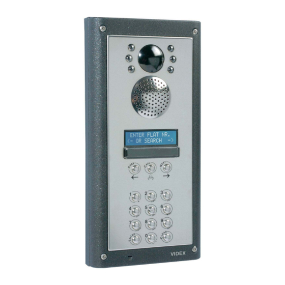
DIGITAL DOOR PANELS PAGE 7 of 80 VX2200 TECHNICAL MANUAL VER1.4... - Page 8 DIGITAL FRONT PANELS The VX2200 digital front panel is based on the “2 wire” BUS (6 wire for non-coax video systems) system and is available in the 800 series & 4000 series modular design and vandal resistant format. The unit includes a keypad with 18-20 vandal resistant push buttons, 6-8 of which are lettered buttons (from “A”...
- Page 9 “0” button pressed until the unit goes back to the display showing CODE. Perform the programming again correcting the error. Alternatively programming a SLAVE as a MASTER PAGE 9 of 80 VX2200 TECHNICAL MANUAL VER1.4...
-
Page 10: Technical Specifications
Technical specifications Memory capacity : 255 users Working voltage : 13 Vdc +/- 10% Max. absorption : about 350 mA Working temperature : -10 +50 C° Relay contacts : 3A@30Vdc, 3A@120Vac PAGE 10 of 80 VX2200 TECHNICAL MANUAL VER1.4... -
Page 11: Digital Door Panel Programming Flow Chart
(1 to 15) NEW : xx NEW : 1 PRESS ‘ENTER’ BUTTON SET LANGUAGE. 0=ENG 1=IT 2=ESP 0=ENG 1=IT 2=ESP (0 to 5) 3=POR 4=FR 5=GER 3=POR 4=FR 5=GER CONTINUED ON NEXT PAGE PAGE 11 of 80 VX2200 TECHNICAL MANUAL VER1.4... - Page 12 C = Forward 1 = .& 2 = ABC 3 = DEF 4 = GHI 5 = JKL 6 = MNO 7 = PQRS 8 = TUV 9 = WXYZ 0 = +-*/ PAGE 12 of 80 VX2200 TECHNICAL MANUAL VER1.4...
-
Page 13: Functional Door Panels
FUNCTIONAL DOOR PANELS PAGE 13 of 80 VX2200 TECHNICAL MANUAL VER1.4... -
Page 14: Functional Door Panels
Functional units are available in the 4000 Series, 800 Series and vandal resistant series. They allow panels with individual call buttons to be connected to the VX2200 “2 wire” BUS. They incorporate the functional interface connections with the speaker unit and are available with 0, 1& 2 button versions (4000 Series can also have 1D, &... - Page 15 Technical specifications Memory capacity : up to 64 users Working voltage : 13 Vdc +/- 10% Max. absorption : about 350 mA Working temperature : -10 +50 C° Relay contacts : 3A@30Vdc, 3A@120Vac PAGE 15 of 80 VX2200 TECHNICAL MANUAL VER1.4...
-
Page 16: Vandal Resistant Functional Door Panels (Amplifier 138)
VANDAL RESISTANT FUNCTIONAL DOOR PANELS Description: This module is used in the VX2200 2 wire audio, 6 wire video functional vandal resistant door panels and includes all features required for audio & video installations. A 13.8Vdc PSU is required to power this system. - Page 17 5 BEEPS (Device 1) Device 2 Device 3 Device 4 Device 5 6 BEEP 7 BEEPS 8 BEEPS 9 BEEPS 10 BEEPS Device 6 Device 7 Device 8 Device 9 Device 10 PAGE 17 of 80 VX2200 TECHNICAL MANUAL VER1.4...
-
Page 18: Isolation Card
Door open LED Output 1 active Spare service button on telephone Output 2 active (Switched 0V) Output 3 active Output 4 active S1 service switch active 12V out fault on one of the outputs PAGE 18 of 80 VX2200 TECHNICAL MANUAL VER1.4... - Page 19 DIP-SW 2204 no. 2204 No. 2204 No. Settings Technical specifications Number of outputs Addressing range : from 0 to 44 Working temperature : -10 +50 C° 12V output current max. : 200mA PAGE 19 of 80 VX2200 TECHNICAL MANUAL VER1.4...
- Page 20 EOL (End of line) which should be in the closed position on the last 894I and open on all others. NOTE: Incorrect fitting of jumper plugs will degrade the video quality Technical specifications Number of outputs Working temperature : -10 +50 C° +20 output current max. : 500mA PAGE 20 of 80 VX2200 TECHNICAL MANUAL VER1.4...
-
Page 21: Bus Exchange Device
If the call is from a block entrance, the system connects the “BUS Out ” (terminals “BO” and “- ”) with the “ Local BUS” (entrance terminals “LB” and “-”) and connects the video outputs (only 2206V) PAGE 21 of 80 VX2200 TECHNICAL MANUAL VER1.4... - Page 22 150 Technical specifications Working voltage : 13 Vdc +/- 10% Max. absorption (audio) : about 100 mA Max. absorption (audio+video) : about 350 mA Working Temperature : -10 +50 C° PAGE 22 of 80 VX2200 TECHNICAL MANUAL VER1.4...
- Page 23 V2-O V2 of balanced video to apartments (Not used in coax mode) NOTE: When using coax for the video, the screens should all be terminated together (and soldered) in a connection block. PAGE 23 of 80 VX2200 TECHNICAL MANUAL VER1.4...
- Page 24 2206N and set to OFF if there are local entrances connected to it. SWITCHES 1 - 4 SWITCH 5 Technical specifications Working voltage : 13 Vdc +/- 10% Working Temperature : -10 +50 C° PAGE 24 of 80 VX2200 TECHNICAL MANUAL VER1.4...
-
Page 25: Concierge Unit
If the user accepts the call, the operator must press the “*” button again, the display shows “CONNECTED”, the user can talk to the visitor and the operator can replace the handset. PAGE 25 of 80 VX2200 TECHNICAL MANUAL VER1.4... - Page 26 (“YY” higher than 1) restart from the beginning of this point to examine all. When “YY” = 1 (last alarm), the concierge stops emitting the acoustic signal; press the “A” button again and PAGE 26 of 80 VX2200 TECHNICAL MANUAL VER1.4...
- Page 27 The display will show “ID PHONE:”, type the phone ID (already programmed by means of the Dip-switch inside the VX2200 telephones, it is a number from 1 to 180) or leave unchanged then press “*” button. Programming via the concierge RS232 connection The RS232 connection can be found on the top edge of the concierge (Jack socket).
-
Page 28: Concierge Unit Programming Flow Chart
PAGE 28 of 80 VX2200 TECHNICAL MANUAL VER1.4... -
Page 29: 2280 Bus Interface Device
Using this device (built into a 5 modules DIN box) it is possible to carry out all the functions available on the VX2200. For example, answer a call from the door panel (and if necessary open the door), call the concierge (if present on the system) and intercommunicate with another user (via concierge). -
Page 30: Audio Telephones
JP2 (red wire on “+” side) and the JP1 jumper (normally on A position) must be moved to the “B” position. Art.3171 & 3172 PAGE 30 of 80 VX2200 TECHNICAL MANUAL VER1.4... - Page 31 “-” terminal and then connect the free “SW” terminal to the “AL” terminal. The signal generated will be received by the concierge and/or by the Art.512DR to activate an additional service. PAGE 31 of 80 VX2200 TECHNICAL MANUAL VER1.4...
- Page 32 Addressing range : from 1 to 180 (BIN code) Working voltage : BUS line Voltage Stand-by absorption : about 0.6 mA Phone max. absorption : about 80mA Working temperature : -10 +50 C° PAGE 32 of 80 VX2200 TECHNICAL MANUAL VER1.4...
-
Page 33: Low Cost 316X Audio Telephones
Addressing range : from 1 to 255 (BIN code) Working voltage : BUS line Voltage Stand-by absorption : about 0.6mA Phone max. absorption : about 80mA Working temperature : -10 +50 C° PAGE 33 of 80 VX2200 TECHNICAL MANUAL VER1.4... -
Page 34: Audio Apartment Station Art.5178
The 5178 is an audio apartment station available in white, silver or carbon fibre ABS plastic and is a surface mount unit which connects to the VX2200 bus via a 4 wire bus. The apartment station has half duplex speech (Handsfree speech) and the facility to switch into simplex speech mode by holding the talk/answer button down. - Page 35 Technical Specifications Addressing range : from 1 to 180 (BIN code) Working voltage : 12Vdc Stand-by absorption : about 6mA Phone max. absorption : about 50mA Working temperature : -10 +50 C° PAGE 35 of 80 VX2200 TECHNICAL MANUAL VER1.4...
-
Page 36: Videophones
Both models of videophones allow the connection of an optional relay board Art.402, for the activation of an external sounder instead of the internal one. PAGE 36 of 80 VX2200 TECHNICAL MANUAL VER1.4... - Page 37 To activate the privacy mode (Art.3376 only) Press the push button marked as : the red “privacy on” LED will switch on. To disable the privacy mode before the configured time expires, press the same push button again. PAGE 37 of 80 VX2200 TECHNICAL MANUAL VER1.4...
- Page 38 R-, red wire to terminal R+) Notes The voltage is available when the monitor is switched on and is normally only used on coax video systems. Only for monitors with memory board Art.35xx. PAGE 38 of 80 VX2200 TECHNICAL MANUAL VER1.4...
- Page 39 (normally the furthest connected) set switch 3 to OFF. Technical Specifications Addressing range : from 1 to 180 (BIN code) Stand-by absorption : about 0,6 mA Videophone max. absorption : about 400mA (20 Volt) Working temperature : -10 +50 C° PAGE 39 of 80 VX2200 TECHNICAL MANUAL VER1.4...
-
Page 40: Video Apartment Station Art.5478, 5476, Sl5478
LED to indicate the operation of the answer/switch off/camera recall/simplex button LED to indicate the operation of the privacy button LED to indicate the operation of the door open button Loudspeaker volume control Call tone volume control Brightness control Colour intensity control PAGE 40 of 80 VX2200 TECHNICAL MANUAL VER1.4... - Page 41 ” button as many times as the number of rings needed (i.e. 6 times = 6 rings, maximum 9 times). • Once the value of rings has been reached, wait 5 seconds for a beep and the LED turning OFF. • The new value is stored. PAGE 41 of 80 VX2200 TECHNICAL MANUAL VER1.4...
- Page 42 : approx 12mA standby on 12V input Call absorption : approx 70mA max on 12Vdc input (During a call) : approx 250mA max on 20Vdc input (During a call) Working temperature : -10 +50 C° PAGE 42 of 80 VX2200 TECHNICAL MANUAL VER1.4...
-
Page 43: Vandal Resistant Apartment Stations Vr5178, Vr5478
The 5178 is an audio apartment station available in white, silver or carbon fibre ABS plastic and is a surface mount unit which connects to the VX2200 bus via a 4 wire bus. The apartment station has half duplex speech (Handsfree speech) and the facility to switch into simplex speech mode by holding the talk/answer button down. - Page 44 − Once the required volume level is reached, wait approx 3 seconds or press again the “ ” button. − The “privacy” LED switches OFF while the “talk” LED switches back ON. PAGE 44 of 80 VX2200 TECHNICAL MANUAL VER1.4...
- Page 45 : approx 12mA standby on 12V input Phone max. absorption : about 50mA : approx 70mA max on 12Vdc input : approx 250mA max on 20Vdc input Working temperature : -10 +50 C° : -10 +50 C° PAGE 45 of 80 VX2200 TECHNICAL MANUAL VER1.4...
-
Page 46: Extension Sounders And Extension Relays
The jumper JP2 enables the configuration of the number of rings or relay pulses: position “A” = 1 ring/pulse, position “B” = 6 rings/pulses. In order to synchronize the local apartment call with the phone, connect the “LB” terminal with the “LB” phone terminal. PAGE 46 of 80 VX2200 TECHNICAL MANUAL VER1.4... -
Page 47: Installation Directions
The wiring diagrams must always be followed (in case of different applications contact Videx technical) and always use cables with sections as per the following table. If the sections proposed are not respected the system may not work correctly. It is advisable to separate the Mains lines (lift, electricity, electricity lock, etc.) from the BUS lines (A distance of at least 10... -
Page 48: Dip-Switch Charts
ON OFF ON OFF ON OFF OFF OFF ON OFF ON OFF ON OFF ON OFF OFF ON ON OFF ON OFF OFF OFF OFF ON ON OFF ON OFF ON OFF PAGE 48 of 80 VX2200 TECHNICAL MANUAL VER1.4... - Page 49 ON ON OFF ON ON ON OFF OFF ON ON OFF ON ON ON ON OFF OFF OFF ON ON ON ON OFF OFF OFF OFF ON ON ON ON ON OFF PAGE 49 of 80 VX2200 TECHNICAL MANUAL VER1.4...
- Page 50 ON OFF OFF ON ON OFF OFF ON ON ON OFF OFF ON ON OFF ON OFF ON OFF ON ON OFF OFF ON OFF OFF ON OFF ON ON OFF ON PAGE 50 of 80 VX2200 TECHNICAL MANUAL VER1.4...
-
Page 51: Troubleshooting Guide
V1 & V2 signals inverted; Check and in case invert the connections; Closing resistances are missing at the end Check and in case apply the closing of the BUS video. resistances on the BUS video. PAGE 51 of 80 VX2200 TECHNICAL MANUAL VER1.4... - Page 52 PAGE 52 of 80 VX2200 TECHNICAL MANUAL VER1.4...
-
Page 53: Basic Audio System Using 317X Audio Telephones (1 Or More Doors)
PAGE 53 of 80 VX2200 TECHNICAL MANUAL VER1.4... -
Page 54: Audio System With 2204 To Apartments
PAGE 54 of 80 VX2200 TECHNICAL MANUAL VER1.4... -
Page 55: Audio With 2204N Full Isolation To Apartments
PAGE 55 of 80 VX2200 TECHNICAL MANUAL VER1.4... -
Page 56: Audio System With Concierge Facility (1 Or More Doors)
PAGE 56 of 80 VX2200 TECHNICAL MANUAL VER1.4... -
Page 57: Level Audio System With Main Gate And Multiple Block Entrances
PAGE 57 of 80 VX2200 TECHNICAL MANUAL VER1.4... -
Page 58: Level System As Above With 2206N Block Exchangers
PAGE 58 of 80 VX2200 TECHNICAL MANUAL VER1.4... -
Page 59: Audio System With Concierge (No Door Panels)
PAGE 59 of 80 VX2200 TECHNICAL MANUAL VER1.4... -
Page 60: Single Entrance Video/Audio System With Concierge Facility
PAGE 60 of 80 VX2200 TECHNICAL MANUAL VER1.4... -
Page 61: Single Entrance Video System (3X71 And 3X76 Videophones)
PAGE 61 of 80 VX2200 TECHNICAL MANUAL VER1.4... -
Page 62: Level Video/Audio System With Multiple Main And Block Entrances
PAGE 62 of 80 VX2200 TECHNICAL MANUAL VER1.4... - Page 63 PAGE 63 of 80 VX2200 TECHNICAL MANUAL VER1.4...
-
Page 64: Level Video System Using The 2206N Block Exchanger
PAGE 64 of 80 VX2200 TECHNICAL MANUAL VER1.4... - Page 65 PAGE 65 of 80 VX2200 TECHNICAL MANUAL VER1.4...
-
Page 66: Multiple Door Video System
PAGE 66 of 80 VX2200 TECHNICAL MANUAL VER1.4... -
Page 67: Example Video System Using Coax Video As Oppose To Non-Coax Video
PAGE 67 of 80 VX2200 TECHNICAL MANUAL VER1.4... -
Page 68: Video System With Additional Camera
PAGE 68 of 80 VX2200 TECHNICAL MANUAL VER1.4... -
Page 69: Video System With Bus Isolation To Apartments
PAGE 69 of 80 VX2200 TECHNICAL MANUAL VER1.4... -
Page 70: Multiple Door Video System With Separate Control Cabinet Per Door
PAGE 70 of 80 VX2200 TECHNICAL MANUAL VER1.4... -
Page 71: Video System With Concierge (No Door Panels)
PAGE 71 of 80 VX2200 TECHNICAL MANUAL VER1.4... -
Page 72: Level Video System With Main And Block Entrances
PAGE 72 of 80 VX2200 TECHNICAL MANUAL VER1.4... - Page 73 PAGE 73 of 80 VX2200 TECHNICAL MANUAL VER1.4...
-
Page 74: Audio System Using The 4000 Series Digital Door Panel
PAGE 74 of 80 VX2200 TECHNICAL MANUAL VER1.4... -
Page 75: Audio System Using The 4000 Series Functional Door Panel
PAGE 75 of 80 VX2200 TECHNICAL MANUAL VER1.4... -
Page 76: Video System Using The 4000 Series Digital Door Panel
PAGE 76 of 80 VX2200 TECHNICAL MANUAL VER1.4... -
Page 77: Audio System Using 5178 Audio Apartment Stations
PAGE 77 of 80 VX2200 TECHNICAL MANUAL VER1.4... -
Page 78: Video System Using 5478 Video Apartment Stations
PAGE 78 of 80 VX2200 TECHNICAL MANUAL VER1.4... - Page 79 PAGE 79 of 80 VX2200 TECHNICAL MANUAL VER1.4...
- Page 80 TEL 0870 300 1240 FAX 0191 224 5678 Southern Office 1 Osprey Trinity Park Trinity Way London E4 8TD FAX 0208 523 5825 TECHNICAL SUPPORT tech@videx-security.com TEL 0191 224 3174 FAX 0191 224 4938 http://www.videx-security.com PAGE 80 of 80 VX2200 TECHNICAL MANUAL VER1.4...
Need help?
Do you have a question about the VX2200 and is the answer not in the manual?
Questions and answers