
Related Manuals for Videx DIGITAL GSM DOOR INTERCOM SYSTEM


Summary of Contents for Videx DIGITAL GSM DOOR INTERCOM SYSTEM
- Page 1 DIGITAL GSM DOOR INTERCOM SYSTEM (Up to 1000 users) TECHNICAL MANUAL EDITION 2.1.1...
- Page 2 PAGE 2 of 32 DIGITAL GSM INTERCOM TECHNICAL MANUAL VER2.1.1...
-
Page 3: Table Of Contents
CONTENTS MANUAL INTRODUCTION ....................................... 4 SYSTEM INTRODUCTION ........................................ 4 PRECAUTIONARY ADVICE ......................................5 SYSTEM COMPONENTS ........................................6 DIGITAL MODULE ........................................ 6 DOOR PANEL MOUNTING FRAMES .................................... 7 POWER SUPPLY ..........................................7 WIRING DIAGRAMS .......................................... 8 PUSH TO EXIT BUTTON AND AUXILIARY INPUTS/OUTPUTS ..........................8 CABLE SIZE GUIDE..........................................9 INSTALLATION .......................................... -
Page 4: Manual Introduction
The information in this manual is intended as an installation and commissioning guide for the digital GSM door intercom system. This manual should be read carefully before the installation commences. Any damage caused to the equipment due to faulty installations where the information in this manual has not been followed is not the responsibility of Videx Security Ltd. -
Page 5: Precautionary Advice
When registering a new SIM you may be asked for the IMEI number. This is the unique serial number of the GSM intercom and can be found on the rear of the module just below the SIM holder on a white label. It’s the long number below the barcode. TIME BAND NOTE: This feature relies on the network providers time zone setting and also if they support ... -
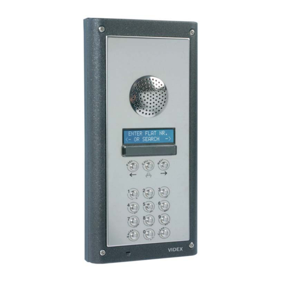
Page 6: System Components
SYSTEM COMPONENTS A system comprises of an intercom panel, power supply, SIM card and antenna. The intercom panel is of modular design allowing it to be customised to the installation requirements by including proximity access control, coded access or bioaccess. DIGITAL MODULE The digital panel is available for the 4000 Series modular design or flush vandal resistant. -
Page 7: Door Panel Mounting Frames
14Vdc. The power supply should be capable of supplying a constant current of no less than 1 amp (If the system is to work with failsafe lock releases or magnetic locks we would recommend a minimum of 2 amps). The following Videx power supplies can be used:- AMR2-12 12-14Vdc 2A switched mode PSU Art.521B... -
Page 8: Wiring Diagrams
WIRING DIAGRAMS PUSH TO EXIT BUTTON AND AUXILIARY INPUTS/OUTPUTS Connections for auxiliary input (Switched 0V) Connections for push to exit button and auxiliary output (Connected to 506N relay) Auxiliary output is also triggered by pressing 6 on the handset during a call. PAGE 8 of 32 DIGITAL GSM INTERCOM TECHNICAL MANUAL VER2.1.1... -
Page 9: Cable Size Guide
CABLE SIZE GUIDE Connections for power supply output to intercom panel and lock release connections. 100m 0.5mm² 1.0mm² 1.5mm² Connections The power supply should be located as close to the intercom panel as possible for best performance. Maximum acceptable resistance for above cables = 3Ω INSTALLATION Check that all components are free from damage before installing (Do not proceed with installation in the event of damage). -
Page 10: Testing, Power Up And Reset
TESTING, POWER UP AND RESET After connecting the power supply, antenna, lock output and auxiliary devices as shown in this manual and before powering up a SIM card must be installed. The SIM holder can be found on the back of the module under the label ‘SIM’. A SIM card from any supplier can be used. -
Page 11: Programming Flowchart
PAGE 11 of 32 DIGITAL GSM INTERCOM TECHNICAL MANUAL VER2.1.1... -
Page 12: 1 - Add/Edit Or Delete An Apartment
1 - ADD/EDIT or DELETE an Apartment From the main menu page, press ‘1’ for APT then press either ‘1’ to add or edit an apartment, ‘2’ to delete an apartment or ‘5’ to return to the main menu page. ADD/EDIT MEMORY LOCATION;... -
Page 13: 3 - Additional Settings
3 – ADDITIONAL SETTINGS From the main menu press ‘3’ for display and language settings then choose 1 to adjust the main display text, 2 to adjust the second display text and 3 to change the display language. LCD1; The display text is usually ‘ENTER NUMBER’. This can be changed to any message up to 16 characters in length. -
Page 14: Exit
.NET 4 framework installed. (The .NET 4 framework can be found on the CD or will be downloaded from the internet during install). After completing the setup, the program will be available from your start menu as Videx GSM. Before running the program, connect the supplied USB cable between a USB port on your PC and the GSM unit. - Page 15 When the program loads, it checks all available ports for the GSM unit. If found, the GSM unit goes online with the PC. From the main screen it is possible to:- Check signal strength: Click on update to retrieve the signal strength from the unit. The signal strength will be between 1 &...
- Page 16 Mobile phone: The mobile phone can be used like a normal mobile phone to make calls. This can be useful when setting up the GSM unit’s SIM card with functions such as switching off voice mail and text alert or listening to the SIM cards balance through the intercom’s speaker.
- Page 17 Speech board Mode: The voice annunciation can be set to speak the number being called as a whole number (i.e. 100 would be spoken as ‘One hundred’) or can be set to speak the numbers individually (i.e. 100 would be spoken as ‘One’ ‘Zero’ ‘Zero’). Alternatively the speech board can be disabled from the drop down menu.
- Page 18 The exit option will close the program. DATA MENU: The data menu is only available when online. From here it is possible to upload the information from the PC to the GSM unit and download information from the GSM unit to the PC. Both upload and download have several options which include the facility to Download all data or upload/download only a section of data which is required and has been changed.
-
Page 19: Programming By Text Message
PROGRAMMING BY TEXT MESSAGE Programming by text message is a simple way to change the apartment programming remotely. This can include changing an apartments telephone numbers, access code, name or settings. If you have a large number of changes you may find programming easier with the PC software or through the keypad and display. -
Page 20: Changing An Apartments Telephone Numbers (Stn) (Std)
CHANGING AN APARTMENTS TELEPHONE NUMBERS (STN) (STD) Each apartment can have up to 2 telephone numbers, a primary number and a divert number should the first not answer or is busy. The STN code stores the primary number and the STD code stores the diverted telephone number. The messages to change numbers are as follows (Replace STN with STD when changing the divert numbers). -
Page 21: Changing An Apartments Dial To Open Setting (Sto)
Example: To change the code to 123456 in apartment 20 would be the following SMS message:- 1111STC20:”123456”? The ? is optional CHANGING AN APARTMENTS DIAL TO OPEN SETTING (STO) Each apartments telephone numbers can be used as dial to open numbers. When this setting is set to 1, dial to open is enabled and when set to 2, dial to open is disabled. -
Page 22: Add A New Apartment Or Query A Memory Location (Mem)
Change the name to yyyyyyyy for apartment n. n can be 1111STTn:”yyyyyyyyyy” 1-6 digits. Change the code yyyyyyyy in apartment n and send a 1111STTn:”yyyyyyyyyy”? confirmation text message to confirm the storage of the new name. Query the name stored for apartment n. A text message 1111STTn:? will be sent to the sender with the stored code for that apartment. -
Page 23: Set Relay Time (Rlt)
and begins from when the call/enter button is pressed. The default time is 40 seconds. The following messages are used to set/check the maximum call time. Store the time nnn (e.g. nnn = 001 - 255 seconds). 1111SPTnnn Store the time nnn (e.g. nnn = 001 - 255 seconds). Also 1111SPTnnn? send a confirmation text back to the sender. -
Page 24: Divert Time (Dit)
DIVERT TIME (DIT) The divert time is the number of seconds to wait for a call to be answered before diverting to the second number. The default time is 15 seconds (The count down begins from when the call/enter button is pressed, but is refreshed when the telephone begins to ring) and can be set to 001 –... -
Page 25: Store The Time Band (Tba)
Store the balance check string for a Vodafone pay as you go. 1111SDL”*#1345#” Store the balance check string for an O pay as you go. 1111SDL”*#10#” STORE THE TIME BAND (TBA) NOTE: This feature relies on the network providers time zone setting and also if they support NITZ (Network Identity and Time zone). -
Page 26: Speech Board Volume (Sbv)
Query the current stored mode. A text message will be 1111SPK? sent to the sender showing the stored mode. SPEECH BOARD VOLUME (SBV) The speech board volume can be set from 0 (Low) to 7 (High) as follows:- Store the mode n = 0 - 7. 1111SBVn Store the mode n = 0 - 7. -
Page 27: System Operation
SYSTEM OPERATION TO MAKE A CALL FROM THE INTERCOM PANEL Enter the required apartment number and press ‘Enter’ or scroll to the required name and press ‘Call’ (Scroll panels only). If the apartment exists the panel will announce and display the calling progress. -
Page 28: Checking The Balance (Bal)
CHECKING THE BALANCE (BAL) *Note: The balance can only be checked if the correct balance check string has previously been stored using the SDL code explained earlier in the manual. The intercom also has the facility to monitor the available credit and then text you to inform you when it has fell below £5.00, €5.00 or $5.00. -
Page 29: Trouble Shooting
TROUBLE SHOOTING SYMPTOM TEST Interference on the speech Check the signal strength ‘1111SIG?’. If the signal strength is to low the GSM module will increase it’s power to compensate causing interference with the speech circuits. Try relocating the antenna or using a more powerful or directional antenna. - Page 30 Enfora certifies that the Enfora Enabler IIG TM MHz GSM Radio Module FCC ID: MIVMLG0208) complies with the RF hazard requirements applicable to broadband PCS equipment operating under the authority of 47 CFR Part 22 or Part 24, Subpart E of the FCC Rules and Regulations.
- Page 31 Date Software Version Revision 06/05/2011 GSM1.0.2 Launch of 4802 19/10/2011 GSM1.0.3 Minor adjustments to the software 14/02/2012 GSM1.0.4 Removed time/date from alpha standby (Some networks don’t support NITZ) 14/03/2012 GSM1.0.5 Dial to open now works with numbers as short as 4 digit 09/05/2012 GSM2.0.0...
- Page 32 Northern Office Videx Security Ltd Unit 4-7 Chillingham Ind. Est. Newcastle Upon Tyne NE6 2XX TEL 0870 300 1240 FAX 0191 224 5678 Southern Office 1 Osprey Trinity Park Trinity Way London E4 8TD FAX 0208 523 5825 TECHNICAL SUPPORT tech@videx-security.com...
Need help?
Do you have a question about the DIGITAL GSM DOOR INTERCOM SYSTEM and is the answer not in the manual?
Questions and answers