Table of Contents
Advertisement
Quick Links
Advertisement
Table of Contents

Related Manuals for Videx VANDAL RESISTANT


Summary of Contents for Videx VANDAL RESISTANT
- Page 1 VANDAL RESISTANT AUDIO AND VIDEO DOOR ENTRY SYSTEMS TECHNICAL MANUAL EDITION 1.1...
- Page 2 PAGE 2 of 24 AUDIO/VIDEO VANDAL RESISTANT TECHNICAL MANUAL VER1.1...
-
Page 3: Table Of Contents
Single entrance multiple button audio wiring diagram Two entrance audio wiring diagram Single entrance video system wiring diagram Two entrance video system wiring diagram Audio system trouble shooting guide Video system trouble shooting guide PAGE 3 of 24 AUDIO/VIDEO VANDAL RESISTANT TECHNICAL MANUAL VER1.1... -
Page 4: Manual Introduction
The information in this manual is intended as an installation and commissioning guide for the standard range of vandal resistant door panels, to be used with standard AC buzzer telephones or with vandal resistant video panels using the Art.890 controller. This manual should be read carefully before the installation commences. -
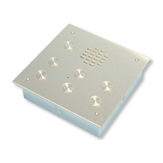
Page 5: Vandal Resistant Panel Layouts
VANDAL RESISTANT PANEL LAYOUT AND SIZES Standard audio panels 1 BUTTON = C 2 BUTTON = B, D (Note: Also available in 125mm 220mm panel style) 3 BUTTON = A, C, E 4 BUTTON = B, D, G, I 5 BUTTON = A, C, E, G, I... - Page 6 Switched negative (Switches off when lock released) Switched negative to lock +12V 12Vdc output 200mA max. V & M Coax in from camera (V=Centre core, M=Screen) V & M Coax out to videophones (V=centre core, M=Screen) PAGE 6 of 24 AUDIO/VIDEO VANDAL RESISTANT TECHNICAL MANUAL VER1.1...
- Page 7 12Vac or dc voltage input Trade button input (Switched 0V) Common connection on relay Normally open connection on relay Normally closed connection on relay For more information see time clock instruction sheet PAGE 7 of 24 AUDIO/VIDEO VANDAL RESISTANT TECHNICAL MANUAL VER1.1...
- Page 8 Centre core of coax from door B camera Screen of coax from door A camera Screen of coax from door B camera 20Vdc to power camera at door A 20Vdc to power camera at door B PAGE 8 of 24 AUDIO/VIDEO VANDAL RESISTANT TECHNICAL MANUAL VER1.1...
- Page 9 CONNECTIONS:- Function Transmit speech to the door panel Receive speech from the door panel Not used Lock Trigger (Switched 0V) Call line (13Vac input to trigger buzzer) Dry contact switch PAGE 9 of 24 AUDIO/VIDEO VANDAL RESISTANT TECHNICAL MANUAL VER1.1...
- Page 10 Coax Screen Speech common for intercommunicating systems Call tone input Speech ground for intercommunicating systems Common of spare buttons Spare button 9 + Coax Spare button 11 cores DIP SWITCH SETTINGS PAGE 10 of 24 AUDIO/VIDEO VANDAL RESISTANT TECHNICAL MANUAL VER1.1...
- Page 11 4 Way Dip Switch (Switches 1 & 2) VIDEO MODE S Button Operation Switch Switch Coax Camera recall Non-Coax Dry contact 3 Way Dip Switch VIDEO MODE continued Switch Coax Non-Coax PAGE 11 of 24 AUDIO/VIDEO VANDAL RESISTANT TECHNICAL MANUAL VER1.1...
-
Page 12: Accessories
Install an appropriate fused spur or isolation switch to isolate the mains. Isolate the mains before carrying out any maintenance work on the system. All intercom and access control cables must be routed separately from the mains. PAGE 12 of 24 AUDIO/VIDEO VANDAL RESISTANT TECHNICAL MANUAL VER1.1... -
Page 13: Cable Size Guide
75Ω Coax cable 75Ω Coax 75Ω Coax cable cable When ever possible connection H1(Tx) should be twisted with connection F(Gnd) and connection G2(Rx) should be twisted with connection F(Gnd) as pairs. PAGE 13 of 24 AUDIO/VIDEO VANDAL RESISTANT TECHNICAL MANUAL VER1.1... -
Page 14: Audio System Block Diagram
V is the centre core of the coax and M is the screen. AUDIO SYSTEM BLOCK DIAGRAM Art.3021, 3101, 3102 Note: Additional cores will be required for auxiliary devices such as push to exit buttons, fireman switches, proximity access control etc. PAGE 14 of 24 AUDIO/VIDEO VANDAL RESISTANT TECHNICAL MANUAL VER1.1... -
Page 15: Video System Block Diagram
PAGE 15 of 24 AUDIO/VIDEO VANDAL RESISTANT TECHNICAL MANUAL VER1.1... -
Page 16: Accessories Connection Guide
ACCESSORIES CONNECTION GUIDE 3101 3101 3101 PAGE 16 of 24 AUDIO/VIDEO VANDAL RESISTANT TECHNICAL MANUAL VER1.1... -
Page 17: Single Entrance Single Button Audio Wiring Diagram
WIRING DIAGRAM This diagram shows a single entrance vandal resistant door panel connected to two audio phones in the same apartment. The lock release shown is fail secure 12Vac. PAGE 17 of 24 AUDIO/VIDEO VANDAL RESISTANT TECHNICAL MANUAL VER1.1... -
Page 18: Single Entrance Multiple Button Audio Wiring Diagram
WIRING DIAGRAM This diagram shows a single entrance vandal resistant door panel connected to multiple apartments. The lock release shown is fail secure 12Vac. We suggest running all telephones back to one point (i.e. junction box next to power supply unit) -
Page 19: Two Entrance Audio Wiring Diagram
WIRING DIAGRAM This diagram shows a two entrance multiple apartments system. 12Vac fail secure lock releases. PAGE 19 of 24 AUDIO/VIDEO VANDAL RESISTANT TECHNICAL MANUAL VER1.1... -
Page 20: Single Entrance Video System Wiring Diagram
WIRING DIAGRAM This diagram shows single entrance VR video door panel connected to a single apartment with two videophones. PAGE 20 of 24 AUDIO/VIDEO VANDAL RESISTANT TECHNICAL MANUAL VER1.1... -
Page 21: Two Entrance Video System Wiring Diagram
WIRING DIAGRAM This diagram shows a two entrance system. Two VR video door panels with two call buttons connected to two apartments. PAGE 21 of 24 AUDIO/VIDEO VANDAL RESISTANT TECHNICAL MANUAL VER1.1... -
Page 22: Audio System Trouble Shooting Guide
Hum on the speech lines Ensure all intercom cables do not run close to higher voltage cables Try another amplifier at the door panel. PAGE 22 of 24 AUDIO/VIDEO VANDAL RESISTANT TECHNICAL MANUAL VER1.1... -
Page 23: Video System Trouble Shooting Guide
Art.890 videophones is not broken. Check terminals G2 and 4 on the Art.890 for No speech from videophone to door panel continuity back to door panel and videophone. PAGE 23 of 24 AUDIO/VIDEO VANDAL RESISTANT TECHNICAL MANUAL VER1.1... - Page 24 FAX 0191 224 5678 Southern Office 1 Osprey Trinity Park Trinity Way London E4 8TD FAX 0208 523 5825 TECHNICAL SUPPORT tech@videx-security.com TEL 0191 224 3174 FAX 0191 224 4938 http://www.videx-security.com PAGE 24 of 24 AUDIO/VIDEO VANDAL RESISTANT TECHNICAL MANUAL VER1.1...
Need help?
Do you have a question about the VANDAL RESISTANT and is the answer not in the manual?
Questions and answers