Videx VIDEOKIT IPVK/6296 Series Installation Handbook
Hide thumbs
Also See for VIDEOKIT IPVK/6296 Series:
- Installation handbook (60 pages) ,
- Installation handbook (60 pages)

Related Manuals for Videx VIDEOKIT IPVK/6296 Series


Summary of Contents for Videx VIDEOKIT IPVK/6296 Series
- Page 1 VIDEOKIT IPVK/6296 SERIES IP one way, two way videokit IPVK IPVKC Rev.0.1 Installation handbook We recommend 66550062-EN - V6.0 - 31/10/21 This equipment is installed by a Competent Electrician, Security or Communications Engineer.
-
Page 2: Table Of Contents
This manual has been written and revised carefully. The instruc- tions and the descriptions which are included in it are referred to VIDEX parts and are correct at the time of print. However, sub- sequent VIDEX parts and manuals, can be subject to changes without notice. -
Page 3: System Components And Available Versions
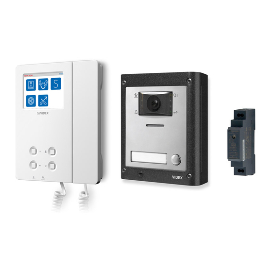
IPVK/6296 Series IP videokit System components and available versions IPVK/6296 Colour videokit. OUTDOOR INDOOR STATION STATION Videophone 135,0 45,0 22,7 Art. 6296 pag. 16 Camera unit Art. 4533 pag. 5 ACCESSORIES Power supply 15,7 Art. HDR-15-12 43,8 120,0 Flush Surface Mounting Mounting Fig. 1 - IPVK/6296 components (measures in mm) IPVK-1/6296 - flush mounting 1 Outdoor station composed of: 1 Colour videophone... - Page 4 IPVK/6296 Series IP videokit System components and available versions IPVKC/6296 Colour videokit plus a codelock module. OUTDOOR INDOOR STATION STATION 135,0 45,0 22,7 Videophone Art. 6296 pag. 16 Camera unit Art. 4533 pag. 5 ACCESSORIES Codelock Power supply module Art. HDR-15-12 Art. 4901 pag. 10 Flush Surface Mounting...
- Page 5 • The camera comprised of illumination LEDs. System connection terminals AVAILABLE VERSIONS To download the programming software VX IP Wizard and obtain the latest firmware and manuals please visit the following web- site and register https://service.videx.it/ Art. 4533-0 Art. 4533X-0 Art. 4533-1 Art. 4533-2 Art. 4533X-1 Art. 4533X-2...
- Page 6 Speaker unit with built-in camera & proximity key reader PROGRAMMING The programming of the module is carried out through the VIDEX IP Wizard software. There are some adjustments available directly on the module: • Microphone volume through the relevant trimmer;...
- Page 7 Art. 4533X Speaker unit with built-in camera & proximity key reader PROGRAMMING TAGS (ONLY ART. 4533X VERSIONS) The programming of the tags is carried out through the VIDEX IP Wizard software. USING TAGS Place a tag in front of the tag reader: ↪ If the tag is programmed, the external module emits two high-pitched “beeping”...
- Page 8 In case of firmware update failure (i.e. because of mains failure or cable disconnec- tion during the update etc.) and the door panel is no longer recognised by the Videx IP Wizard software, you can try to restore it by manually putting it into boot mode.
- Page 9 Supported resolutions: 352x288 (CIF) used in SIP standard mode CAMERA GND Composite video signal ground reference 320x240 used between Videx devices and app Composite video signal input 176x144 (QCIF) used in SIP standard mode Audio codec: G.711 μ-law, A-law...
- Page 10 GENERAL DIRECTIONS FOR INSTALLATION In order to achieve the best results from the schematics described it is necessary to install only original VIDEX equipment, strictly keeping to the items indicated on each schematic and follow these General Directions for Installation: •...
-
Page 11: Art. 4901 Digital Codelock Module
IPVK/6296 Series IP videokit Art. 4901 Digital codelock module LOCK RELEASE BACK EMF PROTECTION A varistor must be fitted across the ter- VARISTOR (MOV) DIODE 1N4002 minals on AC lock release (Fig. 5) and a diode must be fitted across the ter- minals on a DC lock release (Fig. - Page 12 IPVK/6296 Series IP videokit Art. 4901 Digital codelock module PROGRAMMING • Enter the ENGINEER’S CODE: first time type six times 1 (111111 First time six times ENTER THE factory preset) and press ENTER (The red LED will illuminate); 1 “111111” factory "ENGINEER’S CODE"...
- Page 13 IPVK/6296 Series IP videokit Art. 4901 Digital codelock module CONNECTION TERMINALS SIGNALS CLEANING OF THE PLATE Use a clean and soft cloth. Use moderate warm water or non-ag- SW2 Relay 2 command signal (active low) gressive cleansers. SW1 Relay 1 command signal (active low) Do not use: NC3 Relay 3 normally closed contact •...
- Page 14 IPVK/6296 Series IP videokit 4000 Series Surface and flush mounting door station installation EXAMPLE: INSTALLING A FOUR MODULE OUTDOOR STATION fig. 1 fig. 2 fig. 3 fig. 4 fig. 5 fig. 6 fig. 7 fig. 8 fig. 9 fig. 10 fig.
- Page 15 IPVK/6296 Series IP videokit 4000 Series Surface and flush mounting door station installation INSTALLING A SURFACE MOUNT DOOR STATION 1. Place the surface box against the wall (165-170cm between the top of the box and the floor level as shown in Fig. 1) and mark the fixing holes for the wall plugs and the hole for the cables (fig. 2).
- Page 16 “DEVICE NOT INITIALISED”, use the configuration software for site and register the VIDEX IP system (Videx IP Wizard.exe) to setup the device https://service.videx.it/ and the system. LEDS...
-
Page 17: Art. 6296 3.5" Touchscreen Videophone For Ipure System
IPVK/6296 Series IP videokit Art. 6296 3.5" touch screen videophone for IPure system HOME SCREEN The Home screen (Fig. 3) includes navigation buttons, control Date and time Settings Privacy buttons and general information: menu ON/OFF • Settings menu button button button 11:12 Navigate to other screens (for details see “Settings menu”... - Page 18 Press again to disable the service. Privacy service enabled The activation status of the service is also indicated by the LED near tactile programmable push button (unless otherwise set by Videx IP Wizard). EVENT LOG Shows the incoming, outgoing, missed and rejected calls. EVENTS...
- Page 19 Settings menu. 2. Once you enter the correct password the device shows the QR binding code. 3. Open Videx CloudNected app on your smartphone, login or register (if you are not registered yet). 4. Tap the icon on the top left corner of the app, next tap “Device Manager”...
- Page 20 IPVK/6296 Series IP videokit Art. 6296 3.5" touch screen videophone for IPure system SET MELODY Enables you to set the ringtone (three tones available): SET MELODY 1. Tap buttons to select the desired ringtone. The device will play the Tyoe current ringtone. 2.
- Page 21 IPVK/6296 Series IP videokit Art. 6296 3.5" touch screen videophone for IPure system CAMERA SETTINGS Enables you to adjust contrast, brightness and hue for the picture coming CAMERA SETTINGS from any outdoor station: 1. Enter the administrator password and then tap the button.
- Page 22 IPVK/6296 Series IP videokit Art. 6296 3.5" touch screen videophone for IPure system ENABLE OR DISABLE MICROPHONE TAKE A SNAPSHOT REJECT OR CLOSE THE CALL 1. Tap icon to disable the microphone. By default, on every videocall or camera to reject or close the call. 2.
- Page 23 In case of firmware update failure (i.e. because of mains failure or cable dis- connection during the update etc.) and the videophone is no longer recog- nised by the Videx IP Wizard software, you can try to restore it by manually putting it into boot mode.
- Page 24 IPVK/6296 Series IP videokit Art. 6296 3.5" touch screen videophone for IPure system WALL MOUNTING INSTRUCTIONS Fig. 1 Fig. 2 Fig. 3 Fig. 4 Fig. 5 Fig. 6 Fig. 7 Fig. 8 WARNING: Remember to remove the mains before installing the videomonitor. 1.
-
Page 25: Windows Setup Static Ip Address
DESCRIPTION In order to setup the Videx IP system the PC running the VIDEX IP wizard and all the VIDEX IP devices must be connected on the same LAN. Once the physical connection is made, the PC’s network card must be properly set and connected to the LAN mentioned above. To achieve this please follow the instructions below. - Page 26 IP address Under “Network connection”, right click on the network card used for the LAN connection to the VIDEX IP System then click on “Properties” Fig. 4 Edit network card properties Under “Ethernet Properties” slide down to find “Internet Protocol Version 4 (TCP/IPv4)”, click on it...
- Page 27 Note that according to the installation size and the network traffic of the system to which the devices are connected, may happen that some operations some functions may not be immediate: i.e. after a firmware update of a device, may be necessary some seconds before the device is recognized again by the Videx IP Wizard, in these cases please repeat the operation.
-
Page 28: Vx Ip Wizard Wizard Configuration Software For Videx Ip System
• When you operate in “OFFLINE MODE” the header of the “Videx IP Wizard.exe” changes as shown in Fig. 8. » The software temporarily locks the devices during the detection then automatically releases them. - Page 29 IPVK/6296 Series IP videokit VX IP Wizard Wizard configuration software for VIDEX IP System Windows Firewall Warning New devices detected Fig. 2 Fig. 3 MAINTENANCE MODE Apt.1A Device Not Intialised VIDEX 6296 1102 192.168.178.102 IP ADDRESS Please use Videx IP Wizard...
- Page 30 IPVK/6296 Series IP videokit VX IP Wizard Wizard configuration software for VIDEX IP System FILE The “File” menu option (Fig. 9) allows to exit the application and change the software interface language. SETTINGS The “Settings” (Fig. 9) menu allows to edit device global parameters and preferences EDIT DEVICE GLOBAL PARAMETERS Under this menu you can edit the following parameters (Fig.
- Page 31 IPVK/6296 Series IP videokit VX IP Wizard Wizard configuration software for VIDEX IP System File menu Edit Device Global Parameters Fig. 9 Fig. 10 Edit Preferences Fig. 11 - 31 - IPVK/6296 Series - Installation handbook 66550062-EN - V6.0 - 31/10/21...
- Page 32 IPVK/6296 Series IP videokit VX IP Wizard Wizard configuration software for VIDEX IP System UTILITIES This menu option (Fig. 11 on page 31) allows to: • “Create site report” under this menu option can be created a report that shows the system configuration. The report detail level can be selected for each type of the system devices.
- Page 33 IPVK/6296 Series IP videokit VX IP Wizard Wizard configuration software for VIDEX IP System Create site report Reset one or more device to factory defaults Fig. 12 Fig. 13 DEVICE NOT INITIALISED Please, use Videx IP Wizard to set the device...
- Page 34 “Cascade Ringing time” set (both the Videx APP and the SIP ID will continue to ring at the same time for all the call duration), see next pages for a detailed description of the advanced “Cascade Mode:”...
- Page 35 IPVK/6296 Series IP videokit » To delete all the users press the “delete” all button. » To create a user press the create button, edit the “user:” description, set the activation status then press save button. The “User ID” is a progressive ID automatically generated. »...
- Page 36 “Save” button. If you enable the tag detection, the fields “Site Code”, “User Code” are automatically filled when the key is read. Using Videx Proximity keys, when the key length is set to “2 Byte”, the “site code” is not required, the “User Code”...
- Page 37 (“CLIENT SETTINGS”, “VIDEO CODEC” and “AUDIO CODEC” settoms). The door panel can work at the same time with third party SIP server and with VIDEX Cloudnected APP. When a call starts, all involved devices will ring according to cascade settings, the first device that answer will stop call to others.
- Page 38 In the “Example 1” Fig. 26, during a call, will ring at the same time the monitor 1, the Videx App and the programmed SIP ID for 20 seconds, then, for the next 20 seconds, will ring the monitor 2, the Videx App and the programmed SIP ID.
- Page 39 IPVK/6296 Series IP videokit VX IP Wizard Wizard configuration software for VIDEX IP System SETTING UP AN OUTDOOR PANEL 4512 - DIGITAL DOOR PANEL WITH KEYPAD In the device list window (Fig. 28 on page 40), click on the button “Edit Properties” of one “OUTDOOR PANEL” model 4512.
- Page 40 IPVK/6296 Series IP videokit VX IP Wizard Wizard configuration software for VIDEX IP System The “USERS SETTINGS“ tab (Fig. 31) allows users to be stored in the door panel memory. The users are used in combination with access codes and proximity keys for access control purposes. To any user can be linked one or more access code and one or more proximity key so, by disabling the user are automatically disabled the relevant access codes and proximity keys.
- Page 41 “Save” button. If you enable the tag detection, the fields “Site Code”, “User Code” are automatically filled when the key is read. Using Videx Proximity keys, when the key length is set to “2 Byte”, the “site code” is not required, the “User Code”...
- Page 42 IPVK/6296 Series IP videokit VX IP Wizard Wizard configuration software for VIDEX IP System Outdoor Panel 4512 - INPUT OUTPUTS Outdoor panel 4512 - RFID SETTING Fig. 32 Fig. 33 Outdoor Panel 4512 - CODES SETTINGS Outdoor Panel 4512 - SIP CLIENT Fig.
- Page 43 “CAMERA SETTINGS” section, for network connection quality “KEEP ALIVE SETTINGS” and allows the operator to unlink the device from VIDEX CLOUD. Normally default settings do not require changes, operate on them only in case of particular environment condition.
- Page 44 IPVK/6296 Series IP videokit VX IP Wizard Wizard configuration software for VIDEX IP System SETTING UP A VIDEO INTERCOM 6296 In the device list (Fig. 38), click on the button “Edit Properties” of one “VIDEO INTERCOM”. If you are unsure which videophone is which, you can enable the flag “Accept Connections from Devices”...
- Page 45 IPVK/6296 Series IP videokit VX IP Wizard Wizard configuration software for VIDEX IP System “OPEN” tab (Fig. 42) you have the following: In the • For the “IN CONVERSATION AND RINGING” statuses the button can be set as per the options described above 1,2 or 3.
- Page 46 IPVK/6296 Series IP videokit VX IP Wizard Wizard configuration software for VIDEX IP System In the “INPUTS" tab incudes the configuration tabs for “IN1“ and “IN2” active low inputs. For each input are available two operating modes: • “Local Bell” • “Trig Output”...
- Page 47 IPVK/6296 Series IP videokit VX IP Wizard Wizard configuration software for VIDEX IP System Video Intercom - “INPUTS” tab - “IN1” Video Intercom - “INPUTS” tab - “IN2” Fig. 43 Fig. 44 Video Intercom - “OUTPUTS” tab - “OUT1” Video Intercom - “OUTPUTS” tab - “OUT2”...
- Page 48 IPVK/6296 Series IP videokit VX IP Wizard Wizard configuration software for VIDEX IP System The “INTERCOMS” tab (Fig. 47) allows to edit the “intercoms address book” which is the list of the device to which it is allowed the intercommunication: • Select the videophone/intercom to add from the listbox then click on the “...
- Page 49 “KEEP ALIVE SETTINGS” and allows the operator to unlink the device from VI- DEX CLOUD. and unlink the device from VIDEX CLOUD. If for any reason you need to remove the device from the system, the unlink is required otherwise the device remains linked to the same installation.
- Page 50 IPVK/6296 Series IP videokit VX IP Wizard Wizard configuration software for VIDEX IP System SETTING UP AN INTERCOM 3196 In the device list (Fig. 62), click on the button “Edit Properties” of one “INTERCOM” (VX 3196). If you are unsure which intercom is which, you can enable the flag “Accept Connections from Devices”...
- Page 51 IPVK/6296 Series IP videokit VX IP Wizard Wizard configuration software for VIDEX IP System Intercom - General Settings tab Intercom - Buttons tab key button Fig. 51 Fig. 52 Intercom - Buttons tab S1 button Intercom - Buttons tab S2 button Fig.
- Page 52 CLOUD. If for any reason you need to remove the device from the system, the unlink is required otherwise the device remains linked to the same installation. If the device is not linked to VIDEX CLOUD, the “Unlink... ” button is disabled and a red background warning advises that the device is not linked to VIDEX CLOUD.
- Page 53 IPVK/6296 Series IP videokit VX IP Wizard Wizard configuration software for VIDEX IP System Intercom - “INPUTS” tab - “IN1” Intercom - “INPUTS” tab - “IN2” Fig. 57 Fig. 58 Intercom - “SIP” tab Intercom - “ADV. ” Tab Fig. 59 Fig.
- Page 54 IPVK/6296 Series IP videokit VX IP Wizard Wizard configuration software for VIDEX IP System SETTING UP AN ETHERNET RELAY/CLOUDBOX 2505 In the device list (Fig. 61), click on the button “Edit Properties” of one “Ethernet Relay” (VX 2505). If you are unsure which relay is which, you can enable the flag “Accept Connections from Devices”...
- Page 55 IPVK/6296 Series IP videokit VX IP Wizard Wizard configuration software for VIDEX IP System Edit Relay properties 2505 Cloudbox - General Settings tab Fig. 61 Fig. 62 2505 Cloudbox - Inputs tab 2505 Cloudbox - Outputs tab Fig. 63 Fig. 64...
- Page 56 “ADV.” tab (Fig. 67) allows to set parameters for network connection quality “KEEP ALIVE SETTINGS”, to unlink the device from VIDEX CLOUD and to read the binding QRCode for the cloudnected APP. If for any reason you need to remove the device from the system, the unlink is required otherwise the device remains linked to the installation;...
- Page 57 If you are ok to proceed, update the firmware of the device as follows: • Launch the Videx IP wizard, detect the Videx devices then click on edit properties button of the device to update (Fig. 68). • Click the update firmware button (Fig. 69).
- Page 58 A user name and password is required to use this feature. This can be obtained by visiting https://service.videx.it and creating a new account. • From the menu bar click on “Videx Cloud-> Link/Relink All Devices to Videx Cloud” (Fig. 74) then in the new window click on the “next”...
- Page 59 IPVK/6296 Series IP videokit VX IP Wizard Wizard configuration software for VIDEX IP System 15:30 LINK VIDEX APP BINDING CODE: 93C2C369A9FEADCF9D16BFF18451EBDE Site is now linked to the Videx Cloud! Videophone binding code Fig. 78 Fig. 79 Unlink from Videx Cloud Confirm Unlink Fig. 80 Fig.
- Page 60 Before you lauch the VIDEX IP Wizard: • Temporarily disable or switch off any running firewall. • If you cannot disable the firewall for any reason, contact your system administrator to add rules to allow VIDEX IP Wizard for UDP and TCP communications.
- Page 61 IPVK/6296 Series IP videokit VX IP Wizard Wizard configuration software for VIDEX IP System Edit properties for Videx IP Wizard Allow the connection Fig. 88 Fig. 89 SIP CONFIGURATION IN DETAIL This section describe in detail, field by field, the SIP parameters.
-
Page 62: Installation Diagrams
ORANGE-WHITE / ARANCIONE-BIANCO ORANGE / ARANCIONE Title: Data creazione: Foglio 15/06/2017 Titolo: Data modifica: 22/07/2019 Videx Electronics S.p.A. Notes: Autore: Marco@videx.it Via del Lavoro, 1 - 63846 Monte Giberto (FM) Note: Cod.File: Phone: +39 0734 631669 - Fax +39 0734 631669 4533-001.dwg www.videx.it - info@videx.it... - Page 63 ORANGE-WHITE / ARANCIONE-BIANCO ORANGE / ARANCIONE Title: Data creazione: Foglio 16/06/2017 Titolo: Data modifica: 22/07/2019 Videx Electronics S.p.A. Notes: Autore: Marco@videx.it Via del Lavoro, 1 - 63846 Monte Giberto (FM) Note: Cod.File: Phone: +39 0734 631669 - Fax +39 0734 631669 4533-002.dwg www.videx.it - info@videx.it...
- Page 64 ORANGE-WHITE / ARANCIONE-BIANCO ORANGE / ARANCIONE Title: Data creazione: Foglio 16/06/2017 Titolo: Data modifica: 22/07/2019 Videx Electronics S.p.A. Notes: Autore: Marco@videx.it Via del Lavoro, 1 - 63846 Monte Giberto (FM) Note: Cod.File: Phone: +39 0734 631669 - Fax +39 0734 631669 4533-003.dwg www.videx.it - info@videx.it...
- Page 65 ORANGE-WHITE / ARANCIONE-BIANCO ORANGE / ARANCIONE Title: Data creazione: Foglio 16/06/2017 Titolo: Data modifica: 24/07/2019 Videx Electronics S.p.A. Notes: Autore: Marco@videx.it Via del Lavoro, 1 - 63846 Monte Giberto (FM) Note: Cod.File: Phone: +39 0734 631669 - Fax +39 0734 631669 4533-004.dwg www.videx.it - info@videx.it...
- Page 66 ORANGE-WHITE / ARANCIONE-BIANCO ORANGE / ARANCIONE Title: Data creazione: Foglio 16/06/2017 Titolo: Data modifica: 22/07/2019 Videx Electronics S.p.A. Notes: Autore: Marco@videx.it Via del Lavoro, 1 - 63846 Monte Giberto (FM) Note: Cod.File: Phone: +39 0734 631669 - Fax +39 0734 631669 4533-005.dwg www.videx.it - info@videx.it...
- Page 67 ORANGE-WHITE / ARANCIONE-BIANCO ORANGE / ARANCIONE Title: Data creazione: Foglio 16/06/2017 Titolo: Data modifica: 23/07/2019 Videx Electronics S.p.A. Notes: Autore: Marco@videx.it Via del Lavoro, 1 - 63846 Monte Giberto (FM) Note: Cod.File: Phone: +39 0734 631669 - Fax +39 0734 631669 4533-006.dwg www.videx.it - info@videx.it...
- Page 68 ORANGE-WHITE / ARANCIONE-BIANCO ORANGE / ARANCIONE Title: Data creazione: Foglio 16/06/2017 Titolo: Data modifica: 22/07/2019 Videx Electronics S.p.A. Notes: Autore: Marco@videx.it Via del Lavoro, 1 - 63846 Monte Giberto (FM) Note: Cod.File: Phone: +39 0734 631669 - Fax +39 0734 631669 4533-007.dwg www.videx.it - info@videx.it...
- Page 69 ORANGE-WHITE / ARANCIONE-BIANCO ORANGE / ARANCIONE Title: Data creazione: Foglio 16/06/2017 Titolo: Data modifica: 22/07/2019 Videx Electronics S.p.A. Notes: Autore: Marco@videx.it Via del Lavoro, 1 - 63846 Monte Giberto (FM) Note: Cod.File: Phone: +39 0734 631669 - Fax +39 0734 631669 4533-008.dwg www.videx.it - info@videx.it...
- Page 70 IPVK/6296 Series IP videokit Installation diagrams ONE WAY VIDEOCODE KIT WITH DC ELECTRIC LOCK AND STANDARD ROUTER /SWITCH - 70 - IPVK/6296 Series - Installation handbook 66550062-EN - V6.0 - 31/10/21...
- Page 71 IPVK/6296 Series IP videokit Installation diagrams TWO WAY VIDEOCODE KIT WITH DC ELECTRIC LOCK AND STANDARD ROUTER /SWITCH - 71 - IPVK/6296 Series - Installation handbook 66550062-EN - V6.0 - 31/10/21...
- Page 72 - 72 - 66550062-EN - V6.0 - 31/10/21...
- Page 73 - 73 - 66550062-EN - V6.0 - 31/10/21...
- Page 74 - 74 - 66550062-EN - V6.0 - 31/10/21...
- Page 75 DISPOSAL In accordance with the Legislative Decree no. 49 of 14 March 2014 “Implementation of the Directive 2012/19/EU on waste electrical and electronic equipment (WEEE)”. The crossed-out bin symbol on the equipment or on the packaging indicates that when the product reaches the end of its lifetime, it must be collected separately from mixed municipal waste.
- Page 76 MANUFACTURER VIDEX ELECTRONICS S.P.A. FABBRICANTE Via del Lavoro, 1 FABRICANT 63846 Monte Giberto (FM) Italy FABRICANTE Tel (+39) 0734 631669 FABRIKANT Fax (+39) 0734 632475 www.videx.it - info@videx.it FABRICANTE ال� ش كة المص ن ِّ عة CUSTOMER SUPPORT VIDEX ELECTRONICS S.P.A.
Need help?
Do you have a question about the VIDEOKIT IPVK/6296 Series and is the answer not in the manual?
Questions and answers