Videx 4000 Series User Manual
Ip video speaker unit module
Hide thumbs
Also See for 4000 Series:
- Technical manual (80 pages) ,
- Installation instructions manual (44 pages) ,
- Instruction manual (40 pages)
Table of Contents
Advertisement
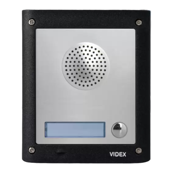
4000 Series
Art. 4503
IP Video Speaker Unit Module
Fig. 1
DESCRIPTION
The 4000 Series IP video speaker unit module can be used with any VIDEX IP device or any computer using a specific MS-Windows Client or any
smartphone/tablet using a specific Android client. It is available in a 0, 1 or 2 button version but for installation with more than 2 call buttons can
be used in combination with the special interface module Art.4513 that enables the connection of up to 64 additional buttons using conventional
button expansion modules.
•
Videx 4000 Series modular system;
•
10/100 Mbit Ethernet interface;
•
Compatible with SIP protocol (it can be connected with VOIP switchboard systems);
•
It recognizes DTMF tones complying with RFC2833 specification;
•
In built web server to set operation parameters;
•
Possibility to connect up to 66 call buttons (an interface module is required to which it is possible to connect standard expansion modules
from the 4000 Series);
•
2 dry contact relay outputs (C, NC, NO) with programmable operation times;
•
1 "active low" input for "push to exit" button;
•
It is possible to set up to 10 IP addresses or SIP ID's for each call button;
•
Client to be used with a PC using MS Windows operating system;
•
Client to be used with a tablet and smartphone using Android operation system;
•
Firmware can be updated through a web server;
•
A wide angle camera is also available.
TERMINALS
L
Not used
H
+12Vdc 12Vdc - 500mA Power supply input
0Vdc
Power Supply Ground
GND
Ground
PTE
"Push to Exit" active low input
RX+
CAT5 cable Orange/white wire
RX–
CAT5 cable Orange wire
TX+
CAT5 cable Green/white wire
TX–
CAT5 cable Green wire
NO2
Relay 2 normally open contact
NC2
Relay 2 normally closed contact
C2
Relay 2 common contact
NO1
Relay 1 normally open contact
NC1
Relay 1 normally closed contact
C1
Relay 1 common contact
Art. 4503 - Installation instructions
4503-0
4503-1
4503-1D
Stainless Steel
Aluminium
High Brass
NETWORK SETTINGS
DEFAULT
IP ADDRESS:
_____ . _____ . _____ . _____
(192.168.1.3)
SUBNET MASK: _____ . _____ . _____ . _____
(255.255.255.0)
GATEWAY:
_____ . _____ . _____ . _____
(192.168.1.1)
Made in Italy
green / verde
green-white / verde-bianco
Not
orange / arancione
Used
orange-white / arancione-bianco
Orange
Orange / White
Fig. 2
TERMINALS TO ART.4513
RX-RS-232 RS-232 Connection RX signal
TX-RS-232
RS-232 Connection TX signal
GND
Ground
1
Connection
TIA/EIA-568-B.1-2001 T568B
Wiring
Day/Night
Infrared LED
Colour Camera
From
Art.4513
Green / White
Green
66250980-EN - V1.0 - 06/02/14
Orange / White
Orange
Green / White
Blue
Blue / White
Green
Brown / White
Brown
Advertisement
Table of Contents

Related Manuals for Videx 4000 Series


Summary of Contents for Videx 4000 Series
- Page 1 DESCRIPTION The 4000 Series IP video speaker unit module can be used with any VIDEX IP device or any computer using a specific MS-Windows Client or any smartphone/tablet using a specific Android client. It is available in a 0, 1 or 2 button version but for installation with more than 2 call buttons can be used in combination with the special interface module Art.4513 that enables the connection of up to 64 additional buttons using conventional...
-
Page 2: Power Supply & Connection
4000 Series Art. 4503 Connection IP Video Speaker Unit Module POWER SUPPLY & CONNECTION For 12Vdc electric lock, follow the connections shown in Fig. 3 otherwise, for 12Vac electric lock, follow the connections shown in Fig. 4. When you use a 12Vac electric lock, it is necessary to install an additional power supply not provided with the kit. -
Page 3: Lock Release
4000 Series Art. 4503 Connection IP Video Speaker Unit Module LOCK RELEASE BACK EMF PROTECTION A capacitor must be fitted across the terminals on AC lock release (Fig. 5) or a diode must be fitted across the terminals on a DC lock release (Fig. - Page 4 4000 Series Art. 4503 Hardware setup IP Video Speaker Unit Module HARDWARE SETUP WITH CROSSOVER CABLE Power up the Art.4503 and connect a crossover cable between the PC/Laptops network connection and the Art.4503 network connection (TCP/IP) as shown in Fig. 1.
- Page 5 4000 Series Art. 4503 Hardware setup IP Video Speaker Unit Module The “Control Panel” window shown on Fig. 4 will appear. Click on “Network and Sharing Center” option. Fig. 4 The window shown on Fig. 5 will appear. Select “Change adap- tor settings”...
- Page 6 4000 Series Art. 4503 Hardware setup IP Video Speaker Unit Module The “Local Area Connection Status” window shown on Fig. 7 will appear. Click on the “Properties” button. Fig. 7 The “Local Area Connection Properties” window shown on Fig. 8 will appear. Highlight “Internet Protocol Version 4 (TCP/IPv4)”...
-
Page 7: Important Note
4000 Series Art. 4503 Hardware setup IP Video Speaker Unit Module The “Internet Protocol Version 4 (TCP/IPv4) Properties” window shown on Fig. 9 will appear. Before changing settings in this window first make a note of the current IP Address, Subnet mask and default gateway settings as you will need to restore them once the task is complete. -
Page 8: Windows Vista
4000 Series Art. 4503 Hardware setup IP Video Speaker Unit Module The “Art.4503 Network Parameters” web page should appear as shown in Fig. 11. The IP Address, SubnetMask and Gateway IP can now be changed. This information can be obtained from the network administrator. -
Page 9: Network Parameters
4000 Series Art. 4503 Web Server IP Video Speaker Unit Module Fig. 1 Login Fig. 2 Network parameters LOGIN PAGE It is recommended that this device is installed by an engineer with an understanding of Ethernet installations and TCP/IP protocols. In the case of installations using existing networks it maybe necessary to request information from the network administrator. -
Page 10: Call Buttons
4000 Series Art. 4503 Web Server IP Video Speaker Unit Module Fig. 3 SIP parameters & Call Buttons Fig. 4 General Settings SIP PARAMETERS & CALL BUTTONS In this section it is possible to enable SIP server communication and address the call buttons to call IP addresses or SIP ID’s of other devices such as videophones, tables, smartphones or PC’s. - Page 11 4000 Series Art. 4503 Web Server IP Video Speaker Unit Module GENERAL SETTINGS General settings can be changed from this tab Fig. 4. LOCK CONFIGURATION The unit includes two integral relays: • Name: it is a descriptive name that can be used to identify the function of that relay (i.e. front door, rear door, gate etc.) •...
-
Page 12: Network Settings
4000 Series Art. 4503 Web Server IP Video Speaker Unit Module CHANGE LOGIN DATA If necessary you can change the access credentials (username & password). To change the access credentials, from the login page (Fig. 1) first enter the current user name and password then click on the “Change login data”... - Page 13 Web Server IP Video Speaker Unit Module • These details can now be used to setup your Videx devices. Ensure you use a free IP address for each device (This should be obtained from the network administrator or for a simple...
- Page 14 4000 Series Note 66250980-EN - V1.0 - 06/02/14 Art. 4503 - Installation instructions...
- Page 15 4000 Series Note 66250980-EN - V1.0 - 06/02/14 Art. 4503 - Installation instructions...
- Page 16 VIDEX ELECTRONICS S.P.A. Via del Lavoro, 1 - 63846 Monte Giberto (FM) Italy Tel (+39) 0734 631669 - Fax (+39) 0734 632475 www.videx.it - info@videx.it Main UK office: Northern UK office: VIDEX SECURITY LTD VIDEX SECURITY LTD 1 Osprey Trinity Park...
Need help?
Do you have a question about the 4000 Series and is the answer not in the manual?
Questions and answers