Table of Contents
Advertisement
Quick Links
OPS150-CS Installation Guide
Note:
Throughout this guide the OPS150-CS may be referred to as the
DFI reserves the right to change the specifications at any time prior to
the product's release. For the latest revision and more details of the
installation procedure, please refer to the user's manual on the website.
www.dfi.com
1
OPS
Module.
Advertisement
Table of Contents

Subscribe to Our Youtube Channel
Related Manuals for DFI OPS150-CS


Summary of Contents for DFI OPS150-CS
- Page 1 Throughout this guide the OPS150-CS may be referred to as the Module. DFI reserves the right to change the specifications at any time prior to the product's release. For the latest revision and more details of the installation procedure, please refer to the user's manual on the website.
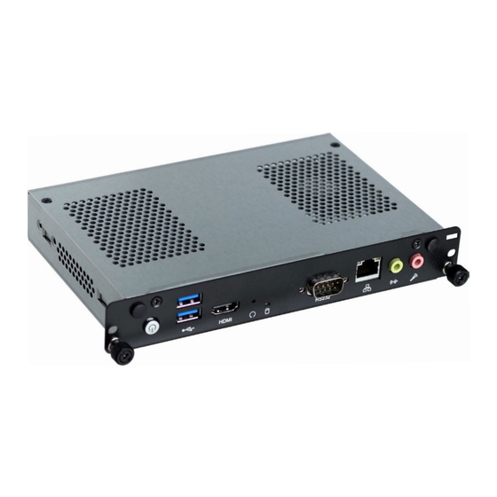
- Page 2 Panel: OPS150-CS Front View HDMI Antenna Hole Antenna Hole USB 3.0 Power Button Reset Button Line-out Mic-in HDD LED Rear View DC-in Jack JAE TX25A (optional)
- Page 3 Installing the OPS150-CS into a Display Integrating a computing system into a digital signage display is made easy by standardizing the connectors and signals between an OPS Module and an OPS-compliant display. Note that the OPS Module does not support hot swapping;...
-
Page 4: Installing A Sodimm
Installing a SODIMM and an M.2 Card The OPS Module is equipped with two SODIMM slots (SO_DIMM1 & 2) in which one can be accessed from the back cover. An additional M.2 slot can also be accessed from the back cover without opening the system's chassis. Opening to the Opening to the SODIMM... -
Page 5: Installing An M.2 Card
Installing an M.2 Card The onboard M.2 Type 2280 (M Key) supports both PCIe NVMe and SATA SSD modules. The other M.2 Type 2230 (E Key) on the top side of the main board provides PCIe & USB signals to accommodate common Wi-Fi and Bluetooth cards. -
Page 6: Removing The Chassis Cover
Removing the Chassis Cover The OPS Module consists of a computing board in a wrapper chassis. Pease observe the following guidelines and follow the procedure to open the system. 1. Make sure the system and all other peripheral devices connected to it have been powered-off. - Page 7 4. Lift the cover up to open the system. 5. The SODIMM (SO_DIMM1) and M.2 (Type 2230) sockets can be accessed after removing the fan and heat sink. Side bracket screws heat sink & fan screws CPU heat sink CPU fan The system adopts a flexible design in which the CPU fan and heat sink can be placed in different orientation (see picture below) so that the opening of the fan can align with the venting holes of your panel.
- Page 8 Board Layout and Jumper Settings: OPS150-CS Top View COM 1 HDD LED Clear CMOS USB 3.0 (JP1) Power-on Battery (J19) Buzzer 8th/9th Gen Intel ® Core™ CPU Intel 1151 H310 M.2 Type 2230-D2-E (PCIe/USB) SPI Flash BIOS JAE TX25A-80P DC-in...
-
Page 9: Connector Pin Assignment
USB: 1*USB 3.0 and 2*USB 2.0 Control and Sensors: 1*UART and Consumer Electronics Control (CEC, note that the OPS150-CS does not support this function) Control and Management Signals: the OPS Module power status, power-on via display panel, OPS Module detect, system fan control, and device reset. - Page 10 TMDS0_2+ DVI-D USB_PP0 TMDS0_2- DVI-D USB_PN0 Ground Ground TMDS0_1+ DVI-D USB_PP1 TMDS0_1- DVI-D USB_PN1 Ground Ground TMDS0_0+ DVI-D USB_PP2 TMDS0_0- DVI-D USB_PN2 Ground Ground TMDS0_CLK+ DVI-D StdA_SSTX+ USB3.0 TMDS0_CLK- DVI-D StdA_SSTX- USB3.0 Ground DDP_HPD DisplayPort StdA_SSRX+ USB3.0 DDP_AUXP DisplayPort StdA_SSRX- USB3.0 DDP_AUXN DisplayPort...
- Page 11 The COM port on the front panel of the OPS Module provides serial communication. The following illustration shows the pin assignments of the COM port: COM 1 (RS232) 1 2 3 4 5 6 7 8 9 The OPS Module also provides pin headers for miscellaneous connectivity. The following tables list the pin assignments of these connectors: LPC (J14) CPU Fan 1 (CN43)
-
Page 12: Physical Dimension
Physical Dimension The overall dimensions of the OPS Module exclusive of the front panel frame is 180 x 30 x 119 mm (W x H x D). The following illustration shows the dimensions of the OPS Module. 180.00 30.00 200.00 933-OPS150-000G A-584-Q-2005...
Need help?
Do you have a question about the OPS150-CS and is the answer not in the manual?
Questions and answers