Table of Contents
Advertisement
Advertisement
Table of Contents

Subscribe to Our Youtube Channel
Related Manuals for Trianco TRO Evolution System Series


Summary of Contents for Trianco TRO Evolution System Series
- Page 1 INSTALLATION AND OPERATING INSTRUCTIONS TRO EVOLUTION SYSTEM...
-
Page 2: Table Of Contents
Index 1.- PRESENTATION ................................4 2.- DESCRIPTION OF COMPONENTS ..........................5 3.- CONTROL ELEMENTS ..............................6 4.- INSTALLATION INSTRUCTIONS ............................7 4.1.- L ..................................7 OCATION 4.2.- H ..............................7 YDRAULIC NSTALLATION 4.3.- E ............................... 7 LECTRICAL ONNECTION 4.4.- O ................................ - Page 3 19.3.- P ................................30 RESSURE DROP 20.- DIAGRAMS AND MEASUREMENTS .......................... 31 21.- ELECTRICAL CONNECTION DIAGRAM ........................32 22.- ELECTRICAL DIAGRAM ............................33 23.- ALARM CODES ................................. 34 24.- BURNER ..................................35 24.1.- A .................................. 35 SSEMBLY 24.2.- B ................................ 35 URNER START 24.3.- A ........................
-
Page 4: Presentation
1.- PRESENTATION Thank you for choosing a TRIANCO heating boiler. You have chosen a boiler that, with a suitable hydraulic installation and using oil for fuel, will provide the ideal level of comfort for your home. This manual forms an essential part of the product and it must be given to the user. Read the warnings and recommendations in the manual carefully, as they contain important information on the safety, use and maintenance of the installation. -
Page 5: Description Of Components
2.- DESCRIPTION OF COMPONENTS 1.- Cast iron body. 2.- Stainless steel condenser. 3.- Safety valve. 4.- Automatic air vent. 5.- Expansion vessel. 6.- Pressure sensor. 7.- Heating circulating pump. 8.- Boiler temperature sensors. 9.- Drainage valve. 10.- Domestic sealed burner. page -5... -
Page 6: Control Elements
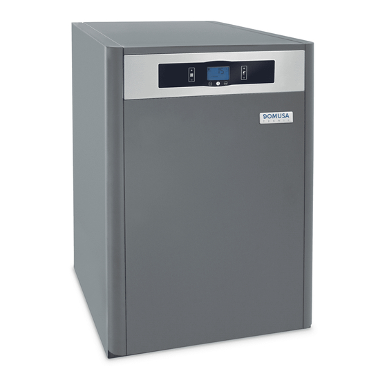
3.- CONTROL ELEMENTS 11. Digital display: This is the boiler functioning display, on which all the operating information, settings and values appear. In standard operating mode (default display), the actual boiler temperature is shown. If any malfunctioning should occur, the corresponding alarm code will appear on the digital display. -
Page 7: Installation Instructions
4.- INSTALLATION INSTRUCTIONS The boiler must be installed by personnel authorised by the Department of Industry in accordance with the applicable regulations and standards in force. However, the following recommendations must be complied with when installing the boiler: 4.1.- Location The boiler must be installed in a sufficiently ventilated site. -
Page 8: Oil Installation
(**) If the pipe constructive materials were sensitive to the action from the flue gases, this distance should be longer than 500 mm. ATTENTION: All the fittings used in the combustion products exhaustion and air intake are to be those supplied by TRIANCO firm. page -8... -
Page 9: Installing Adhw Storage Tank Sanit (Optional )
4.6.- Installing a DHW storage tank Sanit (Optional) The procedure for suitably connecting a Sanit DHW tank to the TRO Evolution System boiler is as follows: - Unplug the boiler from the mains. - Connect a DHW temperature sensor (supplied optionally) to sensor terminal strip J3 (terminals 16 and 17), first removing the resistance (Ra) supplied by default (see “Electrical Connection Diagram"). -
Page 10: Installing The Srfc2/Ev Underfloor Heating Kit (Optional)
Select the anti-legionella function by turning selector 4 to ON (see "Electrical Diagram"). 4.8.- Installing the SRFC2/EV Underfloor Heating Kit (Optional) The procedure for suitably connecting the SRFC2/EV Underfloor Heating Kit to the TRO Evolution System boiler is as follows: - Unplug the boiler from the mains. -
Page 11: Combustion Products Exhaustion
5.- COMBUSTION PRODUCTS EXHAUSTION 5.1.- Combustion products exhaustion and air intake dual-duct device ø80 / ø100 (typr C53) In this type, the combustion products exhaustion and air intake are carried out with separated pipes of Ø80/100mm, by means of the dual-duct outlet Kits of Ø80/100 code CGAS000265. -
Page 12: Double Conduit To Coaxial Exhaustion Transformation (Only For Tro Evolution 30 System )
5.2.- Double conduit to coaxial exhaustion transformation (Only for TRO Evolution 30 System) The boiler TRO Evolution System is given prepared for the exhaustion of the products of combustion and air intake by means of the system of double conduit of Ø80. When you want to carry out the exhaustion of combustion gases by means of coaxial tube of Ø80/125, you will use for it a Kit adaptor for coaxial tube Ø80/125 (given under order) Code CGAS000213 Kit adaptor for coaxial tube 80/125... -
Page 13: Ombustion Products Exhaustion And Air Intake Horizontally Arranged Coaxial Device Øtype Nly For Tro Evolution Ystem )
Combiustion air intake Back exit Lateral exit 90º elbow Ø 80 5.3.- Combustion products exhaustion and air intake horizontally-arranged coaxial device ø80-125 (type C13) (Only for TRO Evolution System) The combustion products exhaustion and air intake can be carried out through concentric pipes of Ø80 mm. -
Page 14: Combustion Products Exhaustion And Air Intake Vertically-Arranged Coaxial Device Ø80-125 (Type C33) (Only For Tro Evolution System)
90º coaxial elbow 80/125 Cod. CGAS000182 Horizontally-arranged outlet 1m 80/125 Cod. CGAS000189 45º coaxial elbow 80/125 1m coaxial duct 80/125 Cod. CGAS000183 Cod. CGAS000184 Examples of installation: L 8 mts. (TRO Evolution 20 System) L 6 mts. (TRO Evolution 30 System) 5.4.- Combustion products exhaustion and air intake vertically-arranged coaxial device ø80-125 (type C33) (Only for TRO Evolution System) The combustion products exhaustion and air intake can be carried out through concentric... -
Page 15: Filling The Installation
90º elbow 80/125 45º elbow 80/125 Cód. CGAS000182 Cód. CGAS000183 1m coaxial duct 80/125 Cód. CGAS000184 Black tile 80/125 Cód. CGAS000075 Vertically outlet 80/125 Black tile 80/125 Cód. CGAS000231 Cód. CGAS000074 Examples of installation: L 10 mts. (TRO Evolution 20 System) L ... -
Page 16: Digital Display
TRO Evolution System boilers have a pressure sensor (6) for controlling the pressure of the installation. If the installation pressure drops below a minimum of 0.5 bar, the boiler will not switch on and a low pressure alarm will appear on the display ("AP"). NOTE: Switching on the boiler with no water inside could result in serious damage. - Page 17 Boiler setpoint temperature selected using the corresponding touch button (12). Underfloor heating installation flow setpoint temperature selected using the corresponding touch button (12). (option SRHFC2/ TRO Evolution System only) DHW setpoint temperature selected using the corresponding touch button (16) (with hot water tank).
-
Page 18: Temperature Selection
8.- TEMPERATURE SELECTION 8.1.- Selecting the boiler set point temperature The desired boiler operating temperature is selected using the touch button, as shown in the figure. To select the desired temperature, touch the "+" or "-" symbols to increase or decrease the temperature respectively. -
Page 19: Selecting The Underfloor Heating Flow Setpoint Temperature (With Srhfc2/ Ev Kit Option)
8.3.- Selecting the Underfloor Heating flow setpoint temperature (with SRHFC2/ EV kit option) When the boiler is installed with the optional SRHFC2/EV underfloor heating kit, the desired flow temperature of the installation can be selected using the touch button as shown in the figure above. -
Page 20: Functioning With A Sanit Hot Water Tank
The TRO Evolution System boiler may be installed together with a hot water tank from the TRIANCO Sanit range, to obtain domestic hot water. For correct installation of the tank, carefully follow the instructions given in the “Installation Instructions” section of this manual. -
Page 21: Additional Functions
10.- ADDITIONAL FUNCTIONS The TRO Evolution System boiler is equipped with an electronic control for efficiently regulating automatic boiler functioning. It also has the following additional control features: 10.1.- Pump anti-block function This function prevents the boiler circulation pumps from seizing up if they have been out of use for a long period. -
Page 22: Anti-Legionella Function (Optional) (With Hot Water Tank Only)
10.6.- Anti-legionella function (optional) (with hot water tank only) This optional function prevents the bacteria causing legionnaire’s disease from proliferating in the hot water accumulated in the tank. Every 7 days, the temperature of the water in the tank is raised to 70 ºC to kill any such bacteria. -
Page 23: E20 Remote Control (Optional)
11.- E20 REMOTE CONTROL (OPTIONAL) A remote control (E20) may optionally be supplied together with the TRO Evolution System boiler. This remote control can be used to fully operate the boiler from any room in the home it is installed in. The E20 remote control governs the settings of heating circuit 1 and the installation’s domestic hot water production (where the case may be). -
Page 24: Functioning With Adhw Tank (Optional )
Conventional heating installation (direct circuit) The maximum temperature, an operating curve for heating circuit 1 (see instructions enclosed with the E20 remote control) and the desired heating times and room temperatures can all be selected on the remote control. The E20 remote control calculates the required boiler temperature at each particular time, depending on the temperature inside the home and the outside weather conditions, in accordance with the operating curve selected (setting HEATSLOPE 1 on the E20), switching the heating on and... -
Page 25: Boiler Security Systems
12.- BOILER SECURITY SYSTEMS The boiler’s electronic control system may activate the following safety cut-outs to stop the boiler functioning. When one of these safety cut-outs occurs, the boiler will stop functioning, a cut-out code will flash on the display and the red alarm warning pilot light will flash on the control panel. -
Page 26: Draining The Boiler
15.- FIRST START-UP For the guarantee to be valid, the boiler must be started up for the first time by an official TRIANCO Technical Assistance Service. Before beginning start-up, the following must be complied with: - The boiler must be electrically connected to the mains. -
Page 27: Boiler Maintenance
17.- BOILER MAINTENANCE To maintain the boiler in perfect working order, a yearly overhaul should be performed by TRIANCO’s authorised personnel. 17.1.- Cleaning the boiler To keep the boiler in perfect working order, we recommend cleaning the boiler chamber, exhaustion ducts and condenser on a yearly basis. A cleaning brush of a suitable size for cleaning the inside of the exhaustion ducts is supplied with the boiler for this purpose. -
Page 28: Anti-Frost Protection
- After cleaning, replace the fume deflectors, the top condenser cover and the top outer cover of the boiler. Then put the cleaning brush back inside the boiler. - The condensation siphon should be cleaned once a year. To do this, remove it and wash it in soapy water. -
Page 29: Technical Data
18.- TECHNICAL DATA TRO Evolution System Condensation Boiler type Heating only Rated heat output rated Useful heat output 19,0 28,7 38,7 Useful heat output (30%) 12,4 Seasonal space heating energy efficiency Ƞ % (PCI) 96,55 97,96 97,29 Useful efficiency Ƞ % (PCS) 91,04 92,38... -
Page 30: Circulating Pump Flow Curves
19.- CIRCULATING PUMP FLOW CURVES The hydrodriving pressure available in the installation at the boiler output can be deduced from the following graphs, having taken the boiler pressure drop into account. 19.1.- Characteristic curves of the pump 19.2.- Regulation of the circulation pump To regulate the speed of the circulation pump BC1 you should navigate to the "UB"... -
Page 31: Diagrams And Measurements
20.- DIAGRAMS AND MEASUREMENTS IC: Heating outlet. IC': Optional heating outlet. IC, IC' MODEL L MEAS. RC: Heating return. TRO Evolution 20 VS: Safety valve. System SC: Condensation water outlet, 1" H. TRO Evolution 30 1"M System SH: Fume exhaustion duct. TRO Evolution 40 System EA: Air intake, Ø80. -
Page 32: Electrical Connection Diagram
21.- ELECTRICAL CONNECTION DIAGRAM There are a series of removable connectors located on the rear of the control panel, for connecting the various options and components for this model. For correct connection, carefully follow the indications shown below: (+) (-) 220 V Ph: Phase. -
Page 33: Electrical Diagram
22.- ELECTRICAL DIAGRAM Pink Black Power supply card 1 2 3 Display Card TS:Security thermostat. J6: Phone relay connector. TH: Fumes thermostat. J8: PCB's connector. SP: Pressure sensor. S1, S2: Boiler model selection switches. R: Phone relay. page -33... -
Page 34: Alarm Codes
23.- ALARM CODES The TRO Evolution System boiler has an electronic circuit which performs continuous self-testing to detect any operating failures in the boiler. When the electronic control detects an operating error, it indicates this by showing an alarm code on the display. The following list describes the possible alarm codes: CODE ALARM... -
Page 35: Burner
For the guarantee to be valid, the burner must be adjusted by an official TRIANCO Technical Assistance Service. Observe the flame. If there is insufficient combustion air, it will be dark in colour and will produce smoke, obstructing the flue outlet. -
Page 36: Primary Air Adjustment
24.4.- Primary air adjustment To adjust the primary combustion air, turn the screw using a 6 mm. Allen key, as shown in the diagram. Turn it clockwise to increase the airflow, and anticlockwise to decrease it. 24.5.- Combustion line adjustment To adjust the combustion line, loosen the combustion line blocking screw "BL". -
Page 37: Oil Pressure Adjustment
3 mm 2/3 mm 24.7.- Oil pressure adjustment To adjust the oil pump pressure, turn the screw (1) clockwise to increase the pressure, and anticlockwise to decrease it. SUNTEC - MOD. AS47C DANFOSS - MOD. BFP 21 L3 1 - Pressure adjustment. 2 –... -
Page 38: Oil Supply Piping Diagrams
24.9.- Oil supply piping diagrams The diagrams and tables below correspond to installations without reductions and with a perfect hydraulic seal. It is recommended to use copper pipes. A pressure drop of 0.4 bar (30 cmHg) must not be exceeded. Intake installation Intake installation Pipe length... -
Page 39: Operating Curves
Preheater 24.11.- Operating curves OVERPRESSURE / FLOW Kg/h Kcal/h 20400 30600 40800 51000 10200 11.8 23.72 35.58 47.44 59.3 24.12.- Nozzles TRO Evolution System boilers are supplied with the burner fitted, together with its corresponding nozzle and a standard pre-adjustment. The following table shows the nozzles and adjustments for each particular model: Burner pressure MODEL... -
Page 40: Electrical Connection Diagram
24.14.- Electrical connection diagram Black Brown Blue Pre-heater TC: Boiler Thermostat. TS: Safety Thermostat. F: Fuse. LB: Cut-off Light. FR: Photocell. TR: Transformer. MB: Oil Pump Motor. EV: Valve. RP: Pre-heater resistance. Ph: Phase. N: Neutral. TP: Pre-heater thermostat. page -40... -
Page 41: Quick Connector
24.15.- Quick connector To connect and disconnect the red oil intake tube to the nozzle, proceed as follows: - Press the connector ring in the direction of the arrow, pulling on the red tube at the same time. T UB E P R E S S R ING QUIC K C ONNE C TOR... -
Page 42: Burner Control Operating Sequence
24.16.- Burner control operating sequence The burner’s LMO control box has a reset button which is the key element for resetting the burner control and activating/deactivating the diagnosis functions. Botón de rearme Reset button The multi-colour LED on the reset button is the indicator for visual diagnosis. -
Page 43: Spare Parts List
25.- SPARE PARTS LIST Burner Pos Code Name Pos Code Name CFER000032 Cable gland CQUE000191 Oil hose CFER000033 Cable gland CQUE000055 Oil filter CQUE000027 Preheater cable CTOR000007 Elbow connector CTOE000063 Burner line D3 CQUE000062 Oil pump Suntec CQUE000155 Turbulator disc D3 CQUE000088 Oil pump Danfoss CQUE000013... - Page 44 Boiler Pos. Code Name Pos. Code Name SEPO000594 Door SEPO002237 Right side 30 HFC W SEPO002235 Door W SEPO002244 Right side 40 HFC W CFER000059 Automatic door-close SEPO000801 Side cover CVAL000034 Drainage valve SEPO002240 Side cover W CFOV000148 Heating circulating pump SCON000803 Condenser CFER000051...
- Page 45 Electrical main board Nº Code Name CELC000294 Control panel embellisher COTR000046 Main board glass CELC000360 Display card CMAZ000128 Cable harness CELC000036 Weidmuller strip 3 poles SEPO001947 Drawer SEPO002249 Drawer W SEPO001325 Panel fastening SEPO002247 Panel fastening W CELC000234 Temperature Evolution sensor 0,90 mts. SEPO001326 Drawer cover SEPO002248...
-
Page 46: Failures
26.- FAILURES This section provides a list of the most common burner and boiler failures. Burner error code We have already mentioned that the burner is equipped with a cut-out system, indicated by the reset button light. It may cut out accidentally, and in this case the steady red light on this button will come on. - Page 47 Circulating pump alarms The high efficiency pumps include a Led (light) which displays their status. PUMP LIGHT DESCRIPTION STATUS CAUSE SOLUTION pump pump Standard functioning functioning operates It is lit green according to its setting Standby mode The pump is in It flashes standby mode green...
- Page 48 Sheffield, S35 22PH Tel: (0114) 2572300 Fax: (0114) 25714199 www.trianco.co.uk Copyright in this brochure and the drawings and illustrations contained within are vested in TR Engineering Ltd and neither the brochure or any part thereof may be reproduced without prior writen consent.
Need help?
Do you have a question about the TRO Evolution System Series and is the answer not in the manual?
Questions and answers